—————— Instruction manual ——————
225
Adap P gain 2
Proportional gain for the range from
Adap speed 1
to
Adap speed 2
. Defined as a
percentage of
Speed P base
.
Adap I gain 2
Integral gain for the range from
Adap speed 1
to
Adap speed 2
. Defined as a percent
-
age of
Speed I base
.
Adap P gain 3
Proportional gain for the range above
Adap speed 2
. Defined as a percentage of
Speed
P base
.
Adap I gain 3
Integral gain for the range above
Adap speed 2
. Defined as a percentage of
Speed I base
.
Adap P gain 4
Proportional gain for the range above
Adap speed 3
. Defined as a percentage of
Speed
P base
.
Adap I gain 4
Integral gain for the range above
Adap speed 3
. Defined as a percentage of
Speed I base
.
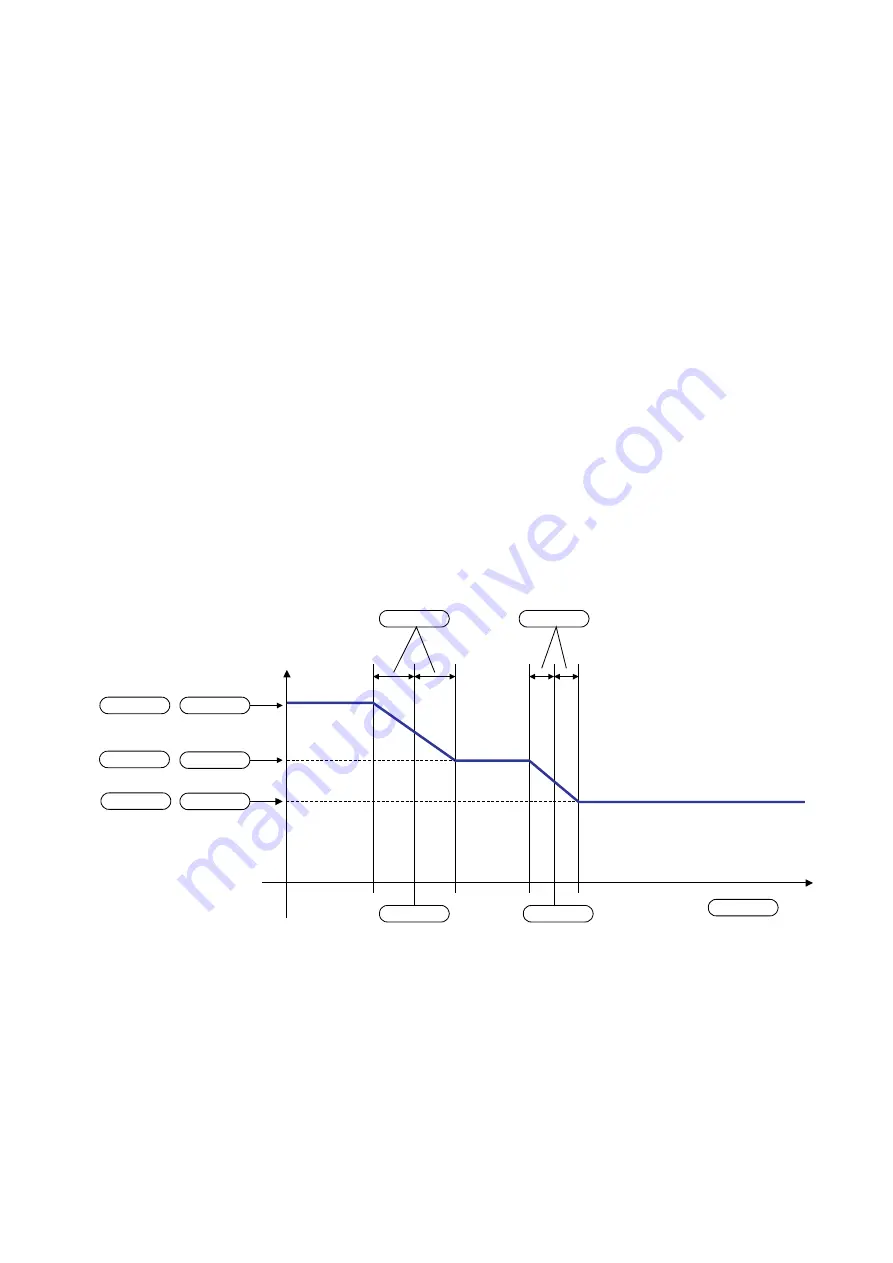
In order to activate Adaptive speed regulation, the function must be enabled with the
Enable spd adap
parameter.
Normally the gain depends on the speed of the drive. It can, however, also vary according to another variable,
defined by the
Adap reference
parameter. This must be selected with the
Select adap type
parameter.
The
Adap speed 1
and
Adap speed 2
parameters are used to define the three ranges that may have different
gains. A parameter set can be defined for each of these ranges, with each set containing an individually definable
P and I component.
The
Adap joint 1
and
Adap joint 2
parameters ensure a smooth transition between the different parameter sets.
The fields must be defined so that
Adap joint 1
and
Adap joint 2
do not overlap.
When the Adaptive speed regulation is enabled (
Enable spd adap
= Enabled) the
Speed P
and
Speed I
parameters
have no effect. They still retain their value and are effective after any disabling of the adaptive speed regulation.
When the drive is not enabled, the gain of the speed regulator is determined by the zero speed logic. See section
6.7.2, “Zero speed logic”.
Adap P gain 1
10 %
Adap P gain 2
10 %
Adap P gain 3
10 %
Adap I gain 1
1 %
Adap I gain 2
1 %
Adap I gain 3
1 %
Adap speed 1
20.3 %
Adap speed 2
40.7 %
Adap joint 1
6.1 %
Adap joint 2
6.1 %
Adap reference
1000 rpm
Figure 6.13.2.1: Adaptive of the speed regulator
Summary of Contents for TPD32-EV-...-2B
Page 1: ... Instruction manual Industrial Application DC drives TPD32 EV ...
Page 372: ... TPD32 EV 372 9 BLOCK DIAGRAM 9 1 CONTROL BLOCK DIAGRAMS ...
Page 373: ... Instruction manual 373 ...
Page 374: ... TPD32 EV 374 ...
Page 375: ... Instruction manual 375 ...
Page 376: ... TPD32 EV 376 ...
Page 377: ... Instruction manual 377 ...
Page 378: ... TPD32 EV 378 ...
Page 379: ... Instruction manual 379 ...
Page 380: ... TPD32 EV 380 ...
Page 381: ... Instruction manual 381 ...
Page 382: ... TPD32 EV 382 ...
Page 383: ... Instruction manual 383 ...
Page 384: ... TPD32 EV 384 ...
Page 385: ... Instruction manual 385 ...
Page 386: ... TPD32 EV 386 ...
Page 387: ... Instruction manual 387 ...
Page 388: ... TPD32 EV 388 ...
Page 389: ... Instruction manual 389 ...
Page 390: ... TPD32 EV 390 ...
Page 391: ... Instruction manual 391 ...
Page 392: ... TPD32 EV 392 ...
Page 393: ... Instruction manual 393 ...
Page 394: ... TPD32 EV 394 ...
Page 395: ... Instruction manual 395 ...
Page 396: ... TPD32 EV 396 ...
Page 397: ... Instruction manual 397 ...
Page 398: ... TPD32 EV 398 ...
Page 399: ... Instruction manual 399 ...
Page 400: ... TPD32 EV 400 ...
Page 401: ... Instruction manual 401 ...
Page 402: ... TPD32 EV 402 ...
Page 501: ... Instruction manual 501 APPENDIX 3 ACCESSORIES A3 1 EAM Adapter Kit EAM1579 EAM1580 ...
Page 503: ......


