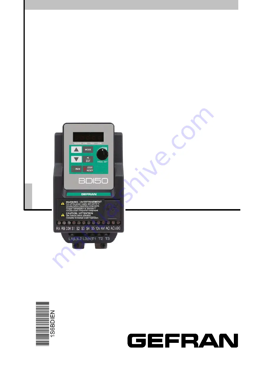
COMPACT V/f & SENSORLESS INVERTER
BDI50
En g lish
User manual
R
ev
. 0.
7
–
-11
-2017
Page 1: ...COMPACT V f SENSORLESS INVERTER BDI50 English User manual Rev 0 7 7 11 2017 ...
Page 2: ...ion which could help us improving this manual The e mail address is the following techdoc gefran com Before using the product read the safety instruction section carefully Keep the manual in a safe place and available to engineering and installation personnel during the product functioning period Gefran S p A has the right to modify products data and dimensions without notice The data can only be ...
Page 3: ...ines 3 11 3 3 1 Main considerations 3 11 3 3 2 Power cables 3 13 3 3 3 Control cable selection and wiring 3 13 3 3 4 Wiring and EMC guidelines 3 14 3 3 5 Failure liability 3 15 3 3 6 Considerations for peripheral equipment 3 17 3 3 7 Ground connection 3 18 3 4 Specifications 3 19 3 4 1 Product Specifications 3 19 3 4 2 General Specifications 3 21 3 5 Standard wiring 3 23 3 5 1 200V Single phase NP...
Page 4: ...ooting 5 5 5 3 Routine and periodic inspection 5 6 5 4 Maintenance 5 7 Chapter 6 Accessories 6 1 6 1 Input choke Specifications 6 1 6 2 Output choke Specifications 6 1 6 3 Fuse Specification 6 1 6 4 Fuse Specification UL Model Recommended 6 2 6 5 Braking Resistor 6 3 6 6 Copy Unit KB BDI VDI 6 4 6 7 Communication options 6 4 6 8 RJ45 to USB connecting Cable 1 8m 6 5 Appendix 1 BDI50 Parameters Set...
Page 5: ...ersonal injury if misused Caution Indicates that the inverter or the mechanical system might be damaged if misused Danger Risk of electric shock The DC link capacitors remain charged for five minutes after power has been removed It is not permissible to open the equipment until 5 minutes after the power has been removed Do not make any connections when the inverter is powered on Do not check parts...
Page 6: ...le objects such as metal If several inverters are placed in the same control panel provide heat removal means to maintain the temperature below 50 degree C to avoid overheat or fire When disconnecting the remote keypad turn the power off first to avoid any damage to the keypad or the inverter Warning This product is sold subject to EN 61800 3 and EN 61800 5 1 In a domestic environment this product...
Page 7: ... direct run on power up is enabled and inverter is set to external run with the run FWD REV switch closed then the inverter will restart Danger Prior to use ensure that all risks and safety implications are considered When the momentary power loss ride through is selected and the power loss is short the inverter will have sufficient stored power for its control circuits to function therefore when ...
Page 8: ...r sizes and relative humidity of 95 Danger Make sure that the power is switched off before disassembling or checking any components 1 5 Inverter Disposal Caution Please dispose of this unit with care as an industrial waste and according to your required local regulations The capacitors of inverter main circuit and printed circuit board are considered as hazardous waste and must not be burnt The Pl...
Page 9: ... Empty not included PNP NPN N NPN input P PNP input NP PNP and NPN Rated voltage 2M 230 Vac 1ph 2T 230 Vac 3ph 4 400 Vac 3ph Software X standard Braking unit B included X not included Keypad K Integrated LED keypad with 5 digits 7 segment display Drive power in kW Mechanical drive sizes BDI50 drive series ...
Page 10: ...0 2015 KXX 2T N 2 1 5 BDI50 2022 KXX 2T N 3 2 2 BDI50 3037 KBX 2T NP 5 3 7 BDI50 4055 KBX 2T NP 8 5 5 BDI50 4075 KBX 2T NP 10 7 5 BDI50 2007 KBX 4 N 3ph 380 480V 10 15 50 60Hz 1 0 75 BDI50 2015 KBX 4 N 2 1 5 BDI50 2022 KBX 4 N 3 2 2 BDI50 3037 KBX 4 NP 5 3 7 BDI50 3055 KBX 4 NP 8 5 5 BDI50 4075 KBX 4 NP 10 7 5 BDI50 4110 KBX 4 NP 15 11 BDI50 2007 KBX 4 P F 1 0 75 BDI50 2015 KBX 4 P F 2 1 5 BDI50 2...
Page 11: ...nsation Altitude Altitude Below 1000m 3281ft It is required to reduce 2 of inverter rated current at each additional 100m The maximum altitude is 3000m See ch 3 2 3 Derating curves Shock 2G 19 6m s for 57 150Hz and below 0 3mm for 10 57Hz According to IEC60068 2 6 standard Installation site Install in an environment that will not have an adverse effect on the operation of the unit and ensure that ...
Page 12: ...3 2 Product Overview Size 3 Size 4 RS485 port Operator Panel TM2 terminal TM1 terminal Ground terminal Operator Panel RS485 port TM2 terminal TM1 terminal Ground terminal Size 1 Size 2 ...
Page 13: ...he metal adaptor plate 3 Push the plastic adaptor forward to lock into position Disassembly Steps 1 Unlock by pushing the snap hooks 2 Retract and remove the plastic Din rail adaptor 3 Unscrew the metal plate Remove Note KIT DIN BDI50 Size 1 Din rail kit part model including the following parts 1 Metal plate adaptor 2 Plastic adaptor 3 Chamfer head screw M3 6 M4 1 Metal plate adaptor 2 Plastic ada...
Page 14: ...s an attachment for the inverter base Refer to Diagram below Din Rail Mounting Dismounting as shown in the diagram below Use a 35mm Din Rail Plastic adaptor plate KIT DIN BDI50 Size 2 Size 2 Din rail kit model M4 Mounting Dismounting Assembly Disassembly Plastic Adaptor plate Snap hook Middle Snap hook Snap hook ...
Page 15: ...3 5 Size 3 Mounting on a flat surface M4 螺丝 Size 4 Mounting on a flat surface M4 螺丝 M4 screw M4 screw ...
Page 16: ...on surfaces that provide good heat dissipation Single unit Installation Install the inverter verticality to obtain effective cooling Multiple Installation 5cm 5cm 12cm 12cm Front view Fan Fan Side view Provide the necessary physical space and cooling based on the ambient temperature and the heat loss in the panel CONTROL PANEL 5cm ...
Page 17: ...3 7 Installation for Grounding kit Grounding kit As bellowed diagram use screw to install EMC metal plate into heatsink Size 1 Size 2 ...
Page 18: ...tor which connect to earth at both ends The shielding must be continuous and if intermediate terminals are used they must be placed in EMC shielded metal boxes 6 Shielded cable for control signal wiring For applications requiring several conductors use cables with small cross section 0 5 mm2 20 AWG For cables 5 and 6 the shielding must be connected to earth at both ends The shielding must be conti...
Page 19: ...rrent In Carrier Frequency kHz 3037 2T 50 4055 2T 50 100 94 10 16 Rated Current In Carrier Frequency kHz 4075 2T 50 2007 2015 2022 4 50 100 70 10 16 Rated Current In Carrier Frequency kHz 3037 4 50 3055 4 50 100 87 10 16 Rated Current In Carrier Frequency kHz 100 84 6 61 5 5 10 16 Rated Current In Carrier Frequency kHz BDI50 3037 2T do not need to decrease the current rating in 50 C ambient temper...
Page 20: ...e to re apply voltage 1year Apply rated voltage 1 of inverter in the normal way Between 1 2 years Apply rated voltage of inverter to the product for one hour before using the inverter 2 years Use a variable AC power supply to 1 Connecting 25 rated voltage of inverter for 30 minutes 2 Connecting 50 rated voltage of inverter for 30 minutes 3 Connecting 75 rated voltage of inverter for 30 minutes 4 C...
Page 21: ...480V AC system 600V AC 5 Control cables should be separated from the power cables Do not place them in the same cable tray or cable trunking to prevent against electrical interference Table 3 1 Size TM1 TM2 Cable Size Tightening torque Cable Size Tightening torque AWG mm kgf cm Ibf in Nm AWG mm kgf cm Ibf in Nm Size 1 22 10 0 34 6 14 12 15 1 37 24 12 0 5 2 5 4 08 3 54 0 4 Size 2 12 24 10 62 1 2 Si...
Page 22: ...wer Supply voltage Specification Voltage Volt Current A 0 4 0 75 0 5 1 220 240V 300 30 1 5 2 2 2 3 220 240V 30 0 75 1 5 2 2 1 2 3 380 480V 600 28 3 7 5 220 240V 300 45 5 5 7 5 7 5 10 220 240V 300 65 3 7 5 5 5 7 5 380 480V 600 45 7 5 11 10 15 380 480V 600 65 ...
Page 23: ...quipment as shown below Inverter IM Machine Insulation transformer Power MCCB 3 3 3 Control Cable selection and Wiring Control cables should be connected to terminal block TM2 Choose power Control cables according to the following criteria Use copper wires with correct diameter and temperature rating of 60 75 C Minimum cable voltage rating for 200V type inverters should be 300VAC Route all cables ...
Page 24: ...ppression of noise emissions the cable armor or shield must be grounded at both ends to the motor and the inverter ground These connections should be as short as possible Motor cable and signal lines of other control equipment should be at the least 30 cm apart BDI50 F series with built in EMC filter All BDI50 F inverters are equipped with an internal EMC filter able to comply the performance leve...
Page 25: ...r windings 4 Metal Cable clamp no more than 150mm from the inverter Note If no enclosure backplate is used then connect the cable shield by a good 360 º termination to the Inverter output terminal E 5 Screened Shielded four core cable 6 Separate Protective Earth wire routed outside motor cable separated be at least 100mm Note this is the preferred method specially for large output cables and long ...
Page 26: ...tween the power source and the inverter If a magnetic contactor a phase capacitor burst absorber and LC or RC circuits have been connected between the inverter and the motor If an incorrectly rated three phase squirrel cage induction motor has been used Note When one inverter is driving several motors the total current of all motors running simultaneously must be less than the rated current of the...
Page 27: ...w 11 kW is connected to a high capacity power source 600kVA or above then an AC reactor can be connected for power factor improvement and reducing harmonics Input noise filter BDI50 inverter has a built in filter first Environment Category C2 or C3 see paragraph 3 3 4 To satisfy the required EMC regulations for your specific application you may require an additional EMC filter Inverter Connect the...
Page 28: ...ent loads Welding machine high power motors Ground each unit separately Ensure that all ground terminals and connections are secure Do not make ground loops when several inverters share a common ground point Note Please leave at least 5cm while installing inverter side by side in order to provide enough cooling space a Correct b Correct c Incorrect L1 L T1 T2 T3 L3 N L2 L1 L T1 T2 T3 L3 N L2 L1 L ...
Page 29: ... 15 5 21 Allovable momentary power loss time s 1 0 1 0 2 0 2 0 Enclosure IP20 230V Class Three phase Sizes BDI50 1007 2015 2022 3037 4055 4075 Output Rating Rated Output Capacity kVA 1 65 2 90 4 00 6 67 9 91 13 34 Rated Output Current A 4 3 7 5 10 5 17 5 26 35 Maximum Applicable Motor HP 1 2 3 5 7 5 10 kW 0 75 1 5 2 2 3 7 5 5 7 5 Output Voltage V Three Phase 0 to 240V Output Frequency Hz Based on ...
Page 30: ... Input current 1 A 4 2 5 6 7 3 10 1 14 3 19 3 26 4 Allovable momentary power loss time s 2 0 2 0 2 0 2 0 2 0 2 0 2 0 Enclosure IP20 1 The input current is calculated value at full rated output current BDI50 Powerloss All inverters are equipped with internal fans excluding BDI50 size 1 Drive Model Power Loss W Heat Loss kcal hr 230 V Class single phase and three phase BDI50 1004 2M 2T 27 0 23 2 BDI...
Page 31: ...models Sizes 3 4 NPN PNP selection from terminals Multifunction digital output 1 relay 16 functions Multifunction analog input 2 AVI 0 10V 2 10V ACI 0 20mA 4 20mA Multifunction analog output 0 10V 5 functions Main features Autotune Torque compensation Slip compensation 8 preset speeds Auto run PID control torque boost V f starting Frequency Fault reset Powerloss ride through DC brake Mechanical br...
Page 32: ...o condensation Altitude 1000 meters or lower Vibration Under 20Hz 1G 9 8m s 20 50Hz 0 6G 5 88m s Communication Function Built in RS 485 with Modbus RTU ASCII standard RJ45 connection BACnet Optionals Profibus DeviceNet CANopen TCP IP Braking unit Built in on 3ph 400V Class and 3ph 200V Class from 3 7kW to 7 5kW EMC filter Built in on F version 1ph 200V Class and 3ph 400V Class Certification CE In ...
Page 33: ...ppressor 10V AVI ACI GND MC Magnetic Contactor RS485 FWD Run Stop REV Run Stop Speed Control External speed potentiometer 10 Kohm or PID input Induction Motor COM MC Thermal relay MC S1 GND 0 10V 2 AO Frequency Indicator 0 10VDC CON2 Thermal relay M 0 20mA P P 2 1 Relay Output Pin 1 to Pin 8 Ground Inverter output Power input Analog Output Multifunction Input Terminals Analog Input ...
Page 34: ...0V AVI ACI GND MC Magnetic Contactor RS485 FWD Run Stop REV Run Stop Speed Control External speed potentiometer 10 Kohm or PID input Induction Motor 24V MC Thermal relay MC S1 GND 0 10V 2 AO Frequency Indicator 0 10VDC CON2 Thermal relay M 0 20mA P P 2 1 Relay Output Pin 1 to Pin 8 Ground Inverter output Power input Analog Output Multifunction Input Terminals Analog Input ...
Page 35: ... AVI ACI GND MC Magnetic Contactor RS485 FWD Run Stop REV Run Stop Speed Control External speed potentiometer 10 Kohm or PID input Induction Motor COM MC Thermal relay MC S1 GND 0 10V 2 AO Frequency Indicator 0 10VDC CON2 Thermal relay M 0 20mA P P 2 1 Relay Output Pin 1 to Pin 8 Ground Inverter output Power input Analog Output Multifunction Input Terminals Analog Input L2 ...
Page 36: ...gnetic Contactor RS485 FWD Run Stop REV Run Stop Speed Control External speed potentiometer 10 Kohm or PID input Induction Motor COM MC Thermal relay MC S1 GND 0 10V 2 AO Frequency Indicator 0 10VDC CON2 Thermal relay M 0 20mA P P 2 1 Relay Output Pin 1 to Pin 8 Ground Inverter output Power input Analog Output Multifunction Input Terminals Analog Input L2 P BR ...
Page 37: ...VI ACI GND MC Magnetic Contactor RS485 FWD Run Stop REV Run Stop Speed Control External speed potentiometer 10 Kohm or PID input Induction Motor 24V MC Thermal relay MC S1 GND 0 10V 2 AO Frequency Indicator 0 10VDC CON2 Thermal relay M 0 20mA P P 2 1 Relay Output Pin 1 to Pin 8 Ground Inverter output Power input Analog Output Multifunction Input Terminals Analog Input L2 P BR ...
Page 38: ... input Induction Motor COM NPN MC Thermal relay MC S1 GND 0 10V 2 AO Frequency Indicator 0 10VDC CON2 Thermal relay M 0 20mA P P 2 1 L2 24V NPN RC SC COM PNP 24V PNP Power input P BR Inverter output Ground Pin 1 to Pin 8 Multifunction Input Terminals Relay Output Analog Output Analog Input NPN PNP input type selection PNP 1 Link SC and COM terminal 2 Use 24v terminal for S1 S5 common point NPN 1 L...
Page 39: ... L2 L3 L2 L3 N P externally connected braking resistor BR T1 Inverter output connect to U V W terminals of motor T2 T3 Ground terminal P BR for BDI50 KBX 2T BDI50 KBX 4 Single phase Note the screw on L2 terminal is removed for the single phase input supply models Three phase BDI50 KXX 2T 200V series Three phase BDI50 KBX 2T BDI50 KBX 4 series L1 L L2 L3 N T1 T2 T3 L1 L L2 L3 N T1 T2 T3 L1 L2 L3 P ...
Page 40: ...ax voltage 30 Vdc Input impedance 6kΩ 10V Built in Power for an external speed potentiometer 10V Max current 20mA AVI Analog voltage input Specification 0 2 10 VDC choose by parameter 04 00 0 10V Input impedance 200kΩ ACI Analog current input Specification 0 4 20mA choose by parameter 04 00 0 20mA Input impedance 499Ω AO Multi function analog output terminal Maximum output 10VDC 1mA 0 10V Max curr...
Page 41: ... input terminals refer to group3 24 VDC 4 5 mA Optical coupling isolation Max voltage30 Vdc Input impedance 6kΩ 10V Built in Power for an external speed potentiometer Max output 20mA 10V Max current 20mA AVI PTC Analog voltage input motor over temperature protection signal input Specification 0 2 10 VDC choose by parameter 04 00 0 10V Input impedance 200kΩ ACI Analog current input Specification 0 ...
Page 42: ...ize 1 D D1 W1 W W2 D2 E E1 E2 H H1 H2 H3 2 Q1 2 Q2 Model Dimension mm Weight kg W W1 W2 H H1 H2 H3 D D1 D2 E E1 E2 Q1 Q2 BDI50 1004 72 63 61 141 131 122 114 141 136 128 2 86 3 81 1 55 4 4 2 2 0 9 1 BDI50 1007 With Built in EMC filter ...
Page 43: ... Q2 D2 H3 E E1 E2 Model Dimension mm Weight kg W W1 W2 H H1 H2 H3 D D1 D2 E E1 E2 Q1 Q2 BDI50 2015 2M BDI50 2015 2T 118 108 108 144 131 121 114 150 144 2 136 4 101 32 96 73 51 5 4 4 2 2 1 4 1 5 BDI50 2022 2M BDI50 2022 2T With Built in EMC filter ...
Page 44: ...W W2 D2 E E1 E2 2 Q1 2 Q2 Model Dimension mm Weight kg W W1 W2 H H1 H2 H3 D D1 D2 E E1 E2 Q1 Q2 BDI50 2007 4 BDI50 2015 4 BDI50 2022 4 118 108 108 144 131 121 114 150 144 2 136 4 101 32 96 73 51 5 4 3 2 2 1 4 1 5 With Built in EMC filter ...
Page 45: ... H H2 D D1 H3 W1 W D2 E E1 E2 2 Q Model Dimension mm Weight kg W W1 H H1 H2 H3 D D1 D2 E E1 E2 Q BDI50 3037 129 118 197 5 177 6 188 154 7 148 143 7 136 102 6 96 48 2 4 5 2 2 2 4 BDI50 3055 4 With Built in EMC filter ...
Page 46: ... H1 D W D2 E E1 D1 H2 H H3 2 Q Model Dimension mm Weight kg W W1 H H1 H2 H3 D D1 D2 E E1 Q BDI50 4055 2T 187 176 273 249 8 261 228 6 190 185 6 177 9 136 84 7 4 5 6 3 6 3 BDI50 4075 BDI50 4110 With Built in EMC filter ...
Page 47: ...nnected the supply system becomes connected to Earth through the Y capacitors on the filter circuit This could result in danger and damage to the Drive Size 1 Size 2 Disconnection steps 1 Remove EMC filter protection cover by screwdriver 2 Remove EMC Filter link by pliers Note Disconnecting the EMC filter link will disables the filter function please consult your local EMC standards requirement Si...
Page 48: ...en the parameters are displayed OFF when the frequency is displayed Variable Resistor FREQ SET Used to set the frequency Keys On Keypad RUN RUN Run at the set frequency STOP RESET Dual function keys STOP Decelerate or Coast to Stop RESET Use to Reset alarms or resettable faults Increment parameter number and preset values Decrement parameter number and preset values MODE Switch between available d...
Page 49: ...ay format Digit LED Letter LED Letter LED Symbol LED 0 A n 1 b o 2 C P _ 3 d q 4 E r 5 F S 6 G t 7 H u 8 J V 9 L Y Digital display indication formats Actual output frequency Set frequency Digits are lit Continually Preset digits flashing Selected digit flashing ...
Page 50: ...ack value Error display Analogue Current Voltage ACID AVI Range 0 1000 LED Status description LED Indicator light Status Frequency line speed Indicator Hz RPM On Menu mode indicator FUN On while not displaying frequency or line speed FWD indicator FWD On while running forward FWD Flashing while stopped in Forward mode REV indicator light REV On while running reverse REV Flashing while stopped in R...
Page 51: ...igits can be set to any of the selections below from 0 to 7 0 Disable display 1 output Current 2 output Voltage 3 DC voltage 4 Temperature 5 PID feedback 6 AVI 7 ACI The highest bit of 12 00 sets the power on the display other bits set the selected display from range 0 7 as Listed above Example1 Set parameter 12 00 10000 to obtain display format shown below MODE MODE MODE 2sec later display Power ...
Page 52: ...unctions 1 Short time press Long time press T1 T2 Quick pressing of these keys will Increment or Decrement the selected digit by one Extended pressing will Increment or Decrement the selected digit continuously 2 ENT Key functions ENT short press for left shift function ENT long press for ENT function T1 T2 Quick pressing of this key will display the preset value of the parameter selected Extended...
Page 53: ...4 Example of keypad operation Example 1 Modifying Parameters Short press ENT once Short press ENT twice Short press once Long press ENT once Frequency Short press once Long press ENT once Short press MODE once ...
Page 54: ...odify bit hundred Modify bit hundred 1 Modify bit hundred 1 Modify bit hundred Modify bit ten Modify bit unit Note frequency command setting will be limited to the range set by parameters for lower upper frequency Modify frequency is stopping Modify frequency is stopping Power supply Power supply 2sec later 2sec later Set frequency display Set frequency display Press run Short press ENT once Short...
Page 55: ...4 8 4 1 5 Operation Control ...
Page 56: ...tions Group 06 Auto Run Auto Sequencer function Group 07 Start Stop command setup Group 08 Drive and motor Protection Group 09 Communication function setup Group 10 PID function setup Group 11 Performance control functions Group 12 Digital Display Monitor functions Group 13 Inspection Maintenance function Parameter notes for Parameter Groups 1 Parameter can be adjusted during running mode 2 Cannot...
Page 57: ...ternal AVI Analog Signal Input 3 External ACI Analog Signal Input 4 External Up Down Frequency Control 5 Communication setting Frequency 6 PID output frequency 00 07 Main and Alternative Frequency Command modes 0 Main Or Alternative Frequency 1 Main frequency Alternative Frequency 0 00 08 Communication Frequency Command 0 00 599 00 Hz 4 00 09 Frequency command Save mode Communication mode 0 Save t...
Page 58: ...01 14 Motor Hunting Prevention Gain 0 100 Sizes 1 2 100V 200V series 7 others 0 01 15 Motor Hunting Prevention Limit 0 100 0 5 0 01 16 Auto Torque Compensation Filter Coefficient 0 1 1000 0 0 1 ms 01 17 Auto torque Compensation Gain 0 100 0 01 18 Auto torque Compensation Frequency 1 30 5 00 2 Hz Group 02 Motor parameters No Description Range Factory Setting Unit Note 02 00 Motor No Load Current By...
Page 59: ...Term S4 3 Preset Speed 2 5 03 3 03 04 Multifunction Input Term S5 4 Preset Speed 4 5 05 17 6 Jog Forward Command 7 Jog Reverse Command 8 Up Command 9 Down Command 10 Acc Dec 2 11 Acc Dec Disabled 12 Main Alternative Run Command select 13 Main Alternative Frequency Command select 14 Rapid Stop Decel to stop 15 Base Block 16 Disable PID Function 17 Reset 18 Auto Run Mode enable 03 05 Reserved 03 06 ...
Page 60: ...nnection detection 03 12 Reserved 03 13 Output frequency detection level Hz 0 00 599 00 0 00 Hz 1 03 14 Frequency Detection band 0 00 30 00 2 00 Hz 1 03 15 Output Current Detection Level 0 1 999 9 0 1 A 03 16 Output Current Detection Period 0 1 10 0 0 1 s 03 17 External Brake Release level 0 00 20 00 0 00 Hz 03 18 External Brake Engage Level 0 00 20 00 0 00 Hz 03 19 Relay Output function type 0 A ...
Page 61: ...08 ACI Bias 0 100 0 1 04 09 ACI Bias Selection 0 Positive 1 Negative 0 1 04 10 ACI Slope 0 Positive 1 Negative 0 1 04 11 Analog Output mode AO 0 Output Frequency 1 Frequency Command 2 Output Voltage 3 DC Bus Voltage 4 Motor Current 0 1 04 12 Analog Output AO Gain 0 1000 100 1 04 13 Analog Output AO Bias 0 1000 0 1 04 14 AO Bias Selection 0 Positive 1 Negative 0 1 04 15 AO Slope 0 Positive 1 Negati...
Page 62: ... 40 00 Hz 1 05 07 Preset Speed6 Hz 50 00 Hz 1 05 08 Preset Speed7 Hz 50 00 Hz 1 05 09 05 16 Reserved 05 17 Preset Speed0 Acctime 0 1 3600 0 10 0 s 1 05 18 Preset Speed0 Dectime 10 0 s 1 05 19 Preset Speed1 Acctime 10 0 s 1 05 20 Preset Speed1 Dectime 10 0 s 1 05 21 Preset Speed2 Acctime 10 0 s 1 05 22 Preset Speed2 Dectime 10 0 s 1 05 23 Preset Speed3 Acctime 10 0 s 1 05 24 Preset Speed3 Dectime 1...
Page 63: ... frequency command 2 0 00 Hz 1 06 03 Auto _ Run Mode frequency command 3 0 00 Hz 1 06 04 Auto _ Run Mode frequency command 4 0 00 Hz 1 06 05 Auto _ Run Mode frequency command 5 0 00 Hz 1 06 06 Auto _ Run Mode frequency command 6 0 00 Hz 1 06 07 Auto _ Run Mode frequency command 7 0 00 Hz 1 06 08 06 15 Reserved 06 16 Auto_ Run Mode running time setting 0 0 0 3600 0 0 0 s 1 06 17 Auto_ Run Mode runn...
Page 64: ...Restart Delay Time 0 0 800 0 0 0 s 07 02 Number of Auto Restart Attempts 0 10 0 07 03 Reset Mode Setting 0 Enable Reset Only when Run Command is Off 1 Enable Reset when Run Command is On or Off 0 07 04 Direct Running After Power Up 0 Enable Direct run on power up 1 Disable Direct run on power up 1 07 05 Delay ON Timer 1 0 300 0 1 0 s 07 06 DC Injection Brake Start Frequency Hz In Stop mode 0 10 10...
Page 65: ...80 0 380 0 760 0 VDC 1 08 05 Electronic Motor Overload Protection Operation Mode xxxx0 Disable Electronic Motor Overload Protection 00001 xxxx1 Enable Electronic Motor Overload Protection xxx0x Motor Overload Cold Start xxx1x Motor Overload Hot Start xx0xx Standard Motor xx1xx Invertor Duty Motor Force Vent 08 06 Operation After Overload Protection is Activated 0 Coast to Stop After Overload Prote...
Page 66: ...ction Level 0 1 Motor Overload Protection Level 1 2 Motor Overload Protection Level 2 0 Group 09 Communication function setup No Description Range Factory Setting Unit Note 09 00 Assigned Communication Station Number 1 32 1 2 3 09 01 Communication Mode Select 0 Modbus RTU code 1 Modbus ASCII code 2 BACnet 0 2 3 09 02 Baud Rate Setting bps 0 4800 1 9600 2 19200 3 38400 2 bps 2 3 09 03 Stop Bit Sele...
Page 67: ... FWD Characteristic 3 Deviation D Control Reverse Characteristic 4 Feedback D Control Reverse Characteristic 5 Frequency Command Deviation D Control FWD Characteristic 6 Frequency Command Feedback D Control FWD Characteristic 7 Frequency Command Deviation D Control Reverse Characteristic 8 Frequency Command Feedback D Control Reverse Characteristic 0 10 04 Feedback Gain Coefficient 0 00 10 00 1 00...
Page 68: ...equency kHz 1 16 5 KHz 11 02 Carrier mode Selection 0 Mode0 3ph PWM modulation 1 Mode1 2ph PWM modulation 2 Mode2 random PWM modulation 1 11 03 Carrier Frequency Reduction by temperature rise 0 disabled 1 enabled 0 11 04 S Curve Acc 1 0 0 4 0 0 00 s 11 05 S Curve Acc 2 0 0 4 0 0 00 s 11 06 S Curve Dec 3 0 0 4 0 0 00 s 11 07 S Curve Dec 4 0 0 4 0 0 00 s 11 08 Skip Frequency 1 0 00 599 00 0 00 Hz 1 ...
Page 69: ...k Temperature 5 PID feedback 6 Analog Signal Input AVI 7 Analog Signal Input ACI 12 01 PID Feedback Display format 0 Integer xxx 0 1 1 One decimal Place xx x 2 Two Decimal Places x xx 12 02 PID Feedback Display Unit Setting 0 xxx 0 1 1 xxxpb pressure 2 xxxfl flow 12 03 Custom Units Line Speed Value 0 65535 1500 1800 rpm 1 12 04 Custom Units Line Speed Display Mode 0 Drive Output Frequency is Displ...
Page 70: ... 01 05 08 cannot be changed 2 All Functions cannot be changed Except for Preset speeds 05 01 05 08 3 Disable All Function 0 13 07 Parameter Lock Code 00000 65535 00000 13 08 Restore Factory Settings 1150 Reset to factory setting 50Hz 220V 380V 1160 Reset to factory setting 60Hz 220V 380V 1250 Reset to factory setting 50Hz 230V 400V 1260 Reset to factory setting 60Hz 230V 460V 1350 Reset to factory...
Page 71: ...ds or for applications with dynamic speed change 00 01 Motor Direction Control Range 0 Forward 1 Reverse 00 01 Is valid in key pad mode only Note When Reverse function is disabled by parameter 11 00 1 setting 00 01 to 1 LOC will be displayed 00 02 Main Run Command Source selection 00 03 Alternative Run Command Source selection Range 0 Keypad 1 External Run Stop Control 2 Communication Parameter 00...
Page 72: ... of the multifunction inputs S1 to S5 and set the relevant parameter 03 00 to 03 04 1 1 Reverse Run Stop mode 00 04 1 Run stop forward reverse Two external switches are required Switch type Two position maintained type this is two wire mode 1 Run Stop switch Select one of the multifunction inputs S1 to S5 and set the relevant parameter 03 00 to 03 04 0 0 Run Stop mode 2 Forward Reverse Switch Sele...
Page 73: ...he relevant parameter 03 00 to 03 04 13 to switch from main to Alternative source When 00 07 1 The Frequency command will be the SUM of Main alternative frequencies I e Main frequency setting 10Hz Alternative frequency setting 5Hz If 00 07 0 frequency setting will be 10Hz OR 5 Hz If 00 07 1 frequency setting will be 10Hz 5 Hz 15Hz 00 08 Communication Frequency Command Range 0 00 599 00 Hz This par...
Page 74: ...Lower limit 0 Hz T 00 14 Acceleration time 1 Range 0 1 3600 0 s 00 15 Deceleration time 1 Range 0 1 3600 0 s 00 16 Acceleration time 2 Range 0 1 3600 0 s 00 17 Deceleration time 2 Range 0 1 3600 0 s Preset Acceleration and Deceleration times by above parameters are the time taken for the output frequency to ramp up or ramp down between the Upper and the lower V F frequency limits Actual accelerati...
Page 75: ...0 The minimum starting frequency V F Maximum output frequency is for VF curve which can be checked from table when VF curve is fixed Maximum output frequency is 01 02 when VF curve is customized or motor rated frequency 02 06 00 18 Jog Frequency Range 1 00 25 00 Hz 00 19 Jog Acceleration Time Range 0 1 25 5 s 00 20 Jog Deceleration Time Range 0 1 25 5 s The JOG function is operational by using the...
Page 76: ...on 01 00 V F pattern 01 00 V F pattern General Use 1 100 B C 1 3 2 5 50 V Hz 599 4 High start torque 2 100 B C 1 3 2 5 50 V Hz 599 5 Decreasing torque 3 100 B C 1 3 25 50 V Hz 599 6 V 100 is the maximum output voltage B C point preset settings will be as table below 01 00 Sizes 1 2 Sizes 3 4 B Xb C Xc B Xb C Xc 1 4 10 8 6 8 3 4 2 5 12 9 5 6 9 3 5 3 6 25 7 7 40 3 4 Setting 01 00 7 provides a flexib...
Page 77: ...Range 0 1 599 00 Hz 01 09 Minimum Frequency Voltage Ratio Range 0 0 100 0 Max output frequency depends on parameter 01 00 for 01 00 7 It can be set by parameter 01 02 For 01 00 7 the maximum output frequency depends on parameter 00 12 frequency upper limit 01 10 Volts Hz Curve Modification Torque Boost Range 0 10 0 Inverter output V F curve settings for points B C can be adjusted by parameter 01 1...
Page 78: ...ers 01 13 01 14 01 15 are used to prevent motor hunting by adjusting the V F output voltage level 01 13 Sets the hunting prevention response time constant in msecs 01 14 Sets the Gain of the hunting prevention 01 15 Sets the hunting prevention voltage limit Diagram below shows the Parameter relationships 01 16 Auto Torque Compensation Filter Coefficient Range 0 1 1000 0 ms 01 17 Auto torque Compen...
Page 79: ...4 32 1 5 50 60 Auto compensation Gain 01 17 Hz Auto compensation Frequency Hz 01 18 ...
Page 80: ...Rated Speed 02 02 approximate Value Motor synchronization speed Rated speed Motor synchronization speed 120 4 Example 4 poles 60Hz induction motor synchronization speed x 60 1800 RPM Note Parameters 02 00 02 01 have to be set according to the specific motor data and in relation to the Inverter rating model parameter 13 00 02 03 Motor Rated Speed Range Slide compensation limit inverter will calcula...
Page 81: ...ent size to the inverter or one size smaller or one size bigger Just need to set the motor parameter and set 02 07 to be 1 Parameters 02 00 02 06 are available both for V F SLV mode Except parameter 02 02 which is for V f 02 13 SLV Slip Compensation Gain Range 0 200 02 14 SLV Torque Compensation Gain Range 0 200 SLV Slip compensation When the load causes the actual motor speed to be reduced below ...
Page 82: ...o the diagram below 02 18 SLV With Load Torque Compensation Gain Range 0 200 Please refer the contents as parameter 02 13 02 14 02 19 SLV Slip Compensation Select Range 0 Slip Compensation Select 1 1 Slip Compensation Select 2 When output current lower or equal to 02 00 no load the value of slip compensation will be equal to 02 13 02 16 slip compensation select 1 When output current higher than 02...
Page 83: ...up5 6 JOG Forward Command Parameters 00 18 00 20 7 JOG Reverse Command Parameters 00 18 00 20 8 Up Command Parameters 00 05 00 06 4 03 06 03 07 9 Down Command Parameters 00 05 00 06 4 03 06 03 07 10 2nd Acc Dec times 11 Disable Acc Dec 12 Main Alternative run source Select Parameters 00 02 00 03 13 Main Alternative Frequency Command Select Parameters 00 05 00 06 14 Rapid Stop controlled decelerati...
Page 84: ...0 S1 03 00 0 FWD STOP S2 03 01 1 REV STOP S1 ON OFF FWD REV ON OFF S2 Hz T Note If both forward and reverse commands are ON it will be treated as a STOP 2 wire method Mode 2 Example RUN STOP and REV FWD from two inputs S1 S2 Set 00 04 1 S1 03 00 0 RUN STOP S2 03 01 1 REV FWD S1 ON OFF FWD REV S2 T Hz ON OFF BDI50 S1 S2 COM FWD STOP REV STOP BDI50 S1 S2 COM RUN STOP REV FWD ...
Page 85: ... according to the table below Preset speed 0 7 and the related acceleration decelerating times should be set in parameter group 5 For example timing diagram refer to Group 5 description Preset speed Function setting and state of any three A B C of terminal S1 S5 Frequency Acc time Dec time terminal A 4 terminal B 3 terminal C 2 speed 0 OFF OFF OFF 05 01 05 17 05 18 speed 1 OFF OFF ON 05 02 05 19 0...
Page 86: ... is kept on continuously the frequency command decreases accordingly and in relation to settings for parameter 03 06 and 3 07 until Zero speed is reached Refer to group 3 parameter description 5 03 00 03 04 10 2nd Acc Dec time When an input terminal is set to function 10 and is turned on the actual acceleration and deceleration time will be according to the time for 2nd Accel Decel set in paramete...
Page 87: ... DI remove ES BDI50 won t run again BDI50 runs again only after giving Run command again 10 03 00 03 04 15 Base Block Coast to stop When DI is on motor free runs to stop When turning off DI remove BB BDI50 will start running from 5Hz below the set frequency to 5Hz above the set frequency and then back to the set frequency 11 03 00 03 04 16 Disable PID Function When an input terminal is set to func...
Page 88: ...pt ON As shown in the diagram below S1 S2 ON ON ON 2Sec OFF OFF 2Sec T Hz ON 03 07 Up Down keep Frequency status after a stop command Range 0 After a stop command in Up Down mode the preset frequency is held as the inverter stops and the UP Down function is disabled 1 After a stop command in Up Down mode the preset frequency is reset to 0 Hz as the inverter stops 2 After a stop command in Up Down ...
Page 89: ... S5 NC NO Normally open NC Normally closed Select as required For selecting Normally Open NO or Normally Closed NC set the relevant digit in parameter 03 09 to 0 or 1 as required Set Parameter 03 09 first before you use the Parameters 00 02 00 03 1 to set the inverter run mode to External multifunction inputs 03 11 Multifunction Output Relay RY1 functions Terminals RB RA Range 0 Run 1 Fault 2 Sett...
Page 90: ... 03 13 03 14 FWD REV Setting Freq 2 Setting Freq 1 Setting Freq 1 Setting Freq 2 2 03 14 Relay Output ON ON ON RUN RUN RUN RUN Command FWD Hz Time 0 When Frequency Detection Range Lower Limit Setting Freq Frequency Detection Range Upper Limit And Frequency Detection Range Lower Limit Output Freq Frequency Detection Range Upper Limit Relay output will be ON Allowable tolerance 0 01 03 13 03 13 03 1...
Page 91: ...n Level 03 13 03 15 Output Current Detection Level Range 0 1 999 9 A 03 16 Output Current Detection Period Range 0 1 10 0 s 03 11 13 RY1 will be on as soon as the output current value Output current detection level 03 15 03 15 Setting range 0 1 15 0 Amps as required according to the rated motor current 03 16 Setting range 0 1 10 0 unit seconds When Output Freq 03 13 Relay output will be ON FWD REV...
Page 92: ...be ON as soon as the actual output frequency reaches the external Brake release level set in parameter 03 17 In decelerating mode RY1 will be OFF as soon as the actual output frequency reaches the external Brake engage level set in parameter 03 18 Timing diagram for 03 17 03 18 is shown below 03 17 03 18 03 11 14 RUN command Hz T ON OFF RUN STOP Timing diagram for 03 17 03 18 is shown below ...
Page 93: ...Range 230V 240 0 400 0 VDC 400V 500 0 800 0 VDC 03 21 Brake Transistor OFF Level Range 230V 240 0 400 0 VDC 400V 500 0 800 0 VDC When DC bus voltage 03 20 Excess voltage will be applied to the external brake resistor When DC bus voltage 03 21 Braking transistor will be switched off Do not set 03 21 03 20 or display will show Err2 which means parameter setting error ...
Page 94: ... F Hz 00 12 I 4 20 4 mA 04 01 AVI signal verification Scan Time Range 1 200 2ms 04 02 AVI Gain Range 0 1000 04 03 AVI Bias Range 0 100 04 04 AVI Bias Selection Range 0 Positive 1 Negative 04 05 AVI Slope Range 0 Positive 1 Negative 04 06 ACI signal verification Scan Time Range 1 200 2ms 04 07 ACI Gain Range 0 1000 04 08 ACI Bias Range 0 100 04 09 ACI Bias Selection Range 0 Positive 1 Negative 04 1...
Page 95: ...0 0 D 100 0 0 1 60Hz 30Hz 0Hz 0V 5V 10V Hz V 04 03 Bias 100 50 0 Upper Frequency A B 60Hz 30Hz 0Hz 0V 5V 10V Hz V 100 50 0 C D 04 03 Bias Negative Bias type and effects of modifying Bias amount by parameter 04 03 and Slope type with parameter 04 05 are shown in Fig 3 4 Figure 3 Figure 4 04 02 04 03 04 04 04 05 04 02 04 03 04 04 04 05 E 100 20 1 0 F 100 50 1 1 60Hz 30Hz 0Hz 2V 5V 10V Hz V 04 03 Bia...
Page 96: ...4 04 05 a 50 50 0 0 c 50 50 0 1 b 200 50 0 0 d 200 50 0 1 60Hz 30Hz 0Hz 0V 5V 10V Hz V 04 03 bias 100 50 0 Upper Frequency b a 37 5Hz 60Hz 30Hz 0Hz 0V 5V 10V Hz V 04 03 bias 100 50 0 Upper Frequency c d 37 5Hz Figure 9 Figure 10 04 02 04 03 04 04 04 05 04 02 04 03 04 04 04 05 e 50 20 1 0 g 50 50 1 1 f 200 20 1 0 h 200 0 0 1 60Hz 18 26Hz 0Hz 1V 4V 10V Hz V 04 03 bias 100 50 0 Upper Frequency e f 60...
Page 97: ...t will be same as the examples shown previously for Analog Voltage Input AVI parameters 4 02 to 4 05 Note the max output voltage is 10V due to the hardware of the circuit Use external devices that require a maximum of 10V dc signal 04 16 Potentiometer frequency curve gain setting Range 0 1000 04 17 Potentiometer frequency curve bias offset setting Range 0 100 04 18 Potentiometer frequency curve bi...
Page 98: ...lect the main or alternative source of frequency command parameters 00 05 00 06 00 07 The modification format will be same as the examples shown previously for Analog Voltage Input AVI parameters 4 02 to 4 05 ...
Page 99: ... 3 Deceleration time 05 25 Preset Speed 4 Acceleration time 05 26 Preset Speed 4 Deceleration time 05 27 Preset Speed 5 Acceleration time 05 28 Preset Speed 5 Deceleration time 05 29 Preset Speed 6 Acceleration time 05 30 Preset Speed 6 Deceleration time 05 31 Preset Speed 7 Acceleration time 05 32 Preset Speed 7 Deceleration time Range 0 1 3600 0 s When 05 00 0 Accel Decl 1 or 2 set by parameters...
Page 100: ...𝑃𝑃𝑃𝑃𝑃𝑃𝑃𝑃 𝑠𝑠𝑠𝑠𝑠𝑠𝑠𝑠𝑠𝑠 1 𝐴𝐴𝐴𝐴𝐴𝐴𝐴𝐴𝐴𝐴𝐴𝐴 𝐷𝐷𝐷𝐷𝐷𝐷𝐷𝐷𝐷𝐷 𝑡𝑡𝑡𝑡𝑡𝑡𝑡𝑡 05 20 10 Hz 01 02 4 s Multi speed run stop cycles with Individual Accel Decel times 05 00 1 Two modes are shown below Mode1 On Off run command Mode2 Continuous run command Mode1 Example 00 02 1 External Run Stop Control 00 04 1 Operation Mode Run stop forward reverse S1 03 00 0 RUN STOP S2 03 01 1 Forward Reverse S3 03 02 2 Preset speed 1 S4 0...
Page 101: ...e f g h i FWD T Hz S2 S3 S4 S5 RUN command Preset speed0 Preset speed1 Preset speed2 Preset speed3 Preset speed4 Preset speed5 RUN STOP ON OFF OFF OFF OFF OFF OFF ON ON ON ON OFF OFF OFF OFF OFF ON When the run command is continuous acceleration and deceleration times for each segment can be calculated as below Ex 05 17 x 05 01 01 02 a 05 19 x 05 02 05 01 01 02 b 05 21 x 05 03 05 02 01 02 c 05 24 ...
Page 102: ...tting2 06 19 Auto_ Run Mode Running Time Setting3 06 20 Auto_ Run Mode Running Time Setting4 06 21 Auto_ Run Mode Running Time Setting5 06 22 Auto_ Run Mode Running Time Setting6 06 23 Auto_ Run Mode Running Time Setting7 Range 0 00 3600 0 s 06 32 Auto_ Run Mode Running Direction0 06 33 Auto_ Run Mode Running Direction1 06 34 Auto_ Run Mode Running Direction2 06 35 Auto_ Run Mode Running Direction...
Page 103: ...ences are set three in forward direction and one in Reverse Auto Run Mode 06 00 1 or 4 Frequency 05 01 15 Hz 06 01 30 Hz 06 02 50 Hz 06 03 20 Hz Sequence Run Time 06 16 20 s 06 17 25 s 06 18 30 s 06 19 40 s Direction 06 32 1 FWD 06 33 1 FWD 06 34 1 FWD 06 35 2 REV Unused Sequence Parameters 06 04 06 07 0 Hz 06 20 06 23 0 s 06 36 06 39 0 05 01 06 01 06 02 06 03 06 16 06 17 06 18 06 19 T Hz RUN comm...
Page 104: ...1 to S5 auto Run enable Example 3 Auto_Run Mode for Single Cycle 06 00 3 or 6 The speed of final step will be held to run Auto Run Mode 06 00 3 or 6 Frequency 05 01 15 Hz 06 01 30 Hz 06 02 50 Hz 06 07 20 Hz Sequence Run Time 06 16 20 s 06 17 25 s 06 18 30 s 06 23 40 s Direction 06 32 1 FWD 06 33 1 06 34 1 06 39 1 Unused Sequence Parameters 06 03 06 06 0 Hz 06 19 06 22 0 s 06 35 06 38 0 05 01 06 01...
Page 105: ...in Auto run mode will be according to the setting of 00 14 00 15 or 00 16 00 17 For Auto sequence 0 The run frequency will be according to keypad frequency set by parameter 05 01 Parameters 06 16 and 06 32 are used to set the sequence Run time and Run direction time Output Frequency Run Command Continue running from unfinished step stop run run time Output Frequency Run Command begin a new cycle s...
Page 106: ...f Auto Restart Attempts Range 0 10 07 02 0 The inverter will not auto restart after trips due to fault 07 02 0 07 01 0 After a trip due to fault the inverter will run with the same frequency before power loss and restarts after an internal delay of 0 5 seconds 07 02 0 07 01 0 After a fault trip the inverter will run with the same frequency before power loss and restart with a delay according the p...
Page 107: ... time Increasing the DC braking current 07 07 can reduce the motor stop time During stop operation If the DC braking start frequency minimum output frequency 01 08 DC braking is activated when the output frequency reaches the minimum output frequency level 07 07 DC Injection Brake Level Range 0 20 Sizes 1 2 Based on the 20 of maximum output voltage 0 100 Sizes 3 4 Based on invertor rated current S...
Page 108: ...d Size 2 100 Corresponds to 100 motot rated voltage Size 3 and Size 4 100 Corresponds to 100 drive rated current 07 11 DC Braking Time at Start Range 0 25 5 s When DC braking time reached ouptut frequency will be based on V F curve DC braking time f t RUN STOP ...
Page 109: ...il the over voltage level is dropped below the setting in 08 02 then the deceleration is resumed 08 03 Trip Prevention Level during continuous Run Mode Range 50 200 Trip prevention adjustment level during continuous Run to prevent over current OC C trips If trip prevention during continuous Run is enabled and an over current occurs due the load such as a sudden transient load then the output frequ...
Page 110: ...elow as an example for overload protection for a standard motor 08 05 xx0xx Cold Start Low Speed 60 Hz Hot Start High Speed 60 Hz 100 150 200 Motor Load Current 02 01 100 5 5 3 5 Overload Protect Time min 3 0 1 0 08 06 Operation After Overload Protection is Activated Range 0 Coast to Stop After Overload Protection is Activated 1 Drive Will Not Trip when Overload Protection is Activated OL1 08 06 0...
Page 111: ... When VDC 360 200V series or VDC 740V 400V series AVR function is disabled for stop and deceleration 08 09 Input phase loss protection Range 0 Disabled 1 Enabled When 08 09 1 On phase loss warring message PF is displayed 08 10 PTC Motor Overheat Function Range 0 Disable 1 Decelerate to stop 2 Coast to stop 3 Continue running when warning level is reached Coast to stop when protection level is reac...
Page 112: ...et level in parameter 08 14 PTC reset level 4 External PTC thermistor characteristics Diagram in figure a shows two curves for Class F and Class H temperatures Tr 150 C in class F Tr 180 C in class H Tr 5 RPTC 550Ω put value of RPTC into formula to calculate the value of V to be set in parameter 08 14 PTC reset level Tr 5 RPTC 1330Ω put value of RPTC into formula to calculate the value of V to be ...
Page 113: ... when using two or more motors connected to the inverter set 08 05 xxx0b and provide external overload protection for each motor e g thermal overload switch When 08 05 xx1xb Hot start the value of hot start will be reset once power off The motors without cooling fan general standard motor heat dissipation of lower speed is low 08 05 can be set to x0xxb The motors with cooling fan special motor or ...
Page 114: ...ad Current 02 01 100 Overload Protect Time min 1 9 4 2 30 9 start activacted point High Speed 60Hz Cold Start 116 150 200 Motor Load Current 02 01 100 Overload Protect Time min 3 2 7 1 51 6 start activacted point When 08 19 2 Low Speed 1 5 Hz Hot Start 100 150 200 Motor Load Current 02 01 100 Overload Protect Time min 1 9 3 5 9 9 Cold Start 100 150 200 Motor Load Current 02 01 100 Overload Protect...
Page 115: ...ction time Range 0 0 25 5 s 09 06 is related to communication test messages When a test message is not responded within the time specified by 09 06 Inverter will be stopped according to the setting of 09 07 and then appear COT on keypad display Once the 09 06 0 inverter will not appear time out 09 07 Communication time out operation selection Range 0 Stop in deceleration time 1 and show COT after ...
Page 116: ...nt The number of errors for the same message are counted and accumulated and if it reaches the setting of 09 08 BDI50 will show Err6 and stop according to the setting of 07 09 09 09 Drive Transmit Wait Time Range 5 65 2ms This parameter is used to set the converter to receive data from the sending date to the beginning of the time 09 10 BACnet stations Range 1 254 ...
Page 117: ...4 70 10 PID function Setup PID block diagram ...
Page 118: ...0 Preset frequency 4 05 05 0 0 1 Preset frequency 5 05 06 1 0 1 Preset frequency 6 05 07 0 1 1 Preset frequency 7 05 08 1 1 1 10 01 PID feedback value selection Range 0 Potentiometer on Keypad 1 External AVI Analog Signal Input 2 External ACI Analog Signal Input 3 Communication setting Frequency Note 10 00 and 10 01 can not be set to the same value 10 02 PID keypad input Range 0 0 100 0 10 03 PID ...
Page 119: ...frequency decreases vice versa When 10 03 5 8 Output frequency PID output frequency frequency command 10 03 1 4 10 04 Feedback Gain coefficient Range 0 00 10 00 10 04 is the calibration gain Deviation set point feedback signal 10 04 10 05 Proportional Gain Range 0 0 10 0 10 05 Proportion gain for P control 10 06 Integral Time Range 0 0 100 0 s 10 06 Integration time for I control 10 07 Derivative ...
Page 120: ...After 30 s Range 1 30 s 10 15 0 As PID feedback value reaches the set point the integral value will not be reset 10 15 1 30 As PID feedback value reaches the set point reset to 0 in 1 30 seconds and inverter stops The inverter will run again when the feedback value differs from the set point value 10 16 Allowable Integration Error Margin Unit 1 Unit 1 8192 Range 0 100 10 16 0 100 unit value Restar...
Page 121: ...e 0 999 10 22 Min PID Feedback Level Range 0 999 Example If 10 21 100 and 10 22 50 and the unit for the range from 0 to 999 will be defined with the parameters setting of 12 02 actual feedback value variation range will be scaled to 50 and 100 only for display as Shown below 10 21 100 10 22 50 Min 0 0V 0mA or 2V 4mA Max 100 10V 20mA 999 PID fback ...
Page 122: ...le torque applications such as Fan pump It reduces the Output transistor switching losses Carrier frequency will be according to parameter 11 01 with the exception noted below Note If 11 01 2KHz 11 03 0 Auto carrier frequency change is disabled and the following conditions apply then 2 phase PWM will automatically change to 3 phase PWM with the carrier frequency 2 3 11 01 Conditions During Acceler...
Page 123: ...setting parameter 12 00 04000 70 80 t1 t2 T 0 Temperature Carrier Frequency 10K 4K t1 t2 T 0 11 04 S Curve Acc 1 11 05 S Curve Acc 2 11 06 S Curve Dec 3 11 07 S Curve Dec 4 Range 0 0 4 0 s Use S Curve parameters where a smooth acceleration or deceleration action is required this will prevent possible damage to driven machines by sudden acceleration deceleration S1 S2 S3 S4 RUN command Actual outpu...
Page 124: ...ample 11 08 10 00 Hz 11 09 20 00 Hz 11 10 30 00 Hz 11 11 2 00 Hz 2Hz 8 12Hz 2Hz 18 22Hz Skip frequency 2Hz 28 32Hz 10Hz 20Hz 30Hz 11 13 Regeneration Prevention Function Range 0 Regeneration prevention function is disabled 1 Regeneration prevention function is enabled 2 Regeneration prevention function is enabled only during constant speed Regeneration Prevention Function During excessive energy re...
Page 125: ...set too low then over voltage protection will not be reached but the actual deceleration time will be extended 11 15 Regeneration Prevention Frequency Limit Range 0 00 15 00 Hz Sets the regeneration prevention frequency limit 11 16 Regeneration Prevention Voltage Gain Range 0 200 11 17 Regeneration Prevention Frequency Gain Range 0 200 Parameters 11 16 11 17 can be used to enhance the response of ...
Page 126: ...and The output frequency from the speed control system is then used to adjust the torque reference as shown in the diagram below P 11 18 I 11 19 Frequency Reference Speed Observer Feedback D 11 20 Torque Reference Torque Limit 11 21 Stop Key Selection Range 0 Enable Stop Key when Run Command not from Keypad 1 Disable Stop Key when Run Command not from Keypad When run command comes from control ter...
Page 127: ...show this value when inverter output frequency reaches the motor name plate frequency 50Hz or 60 Hz as appropriate The line speed display is linearly proportional to the output frequency 0 to 50Hz or 0 60 Hz as appropriate Motor synchronous speed 120 x Rated frequency Number of poles 12 04 Custom Units Line Speed Display Mode Range 0 Drive Output Frequency is Displayed 1 Line Speed is Displayed in...
Page 128: ...ollowing figure shows 12 05 display status when S2 S3 S4 inputs are ON and S1 S5 are OFF but RY1 is ON RY1 12 06 Output Power Range It needs to set motor rated power correctly parameter 02 05 12 07 Motor Current Percentage Range The ratio of drive output current and motor rated current it needs to set motor rated current correctly parameter 02 01 ...
Page 129: ...ansferred to 3 xxx and the one in 1 xxx to 2 xxx The recent fault will be stored in the empty register 1 xxx Use Up and Down keys to scroll between the fault registers Pressing reset key when parameter 13 02 is displayed then all three fault registers will be cleared and the display for each register will change to 1 2 3 E g fault log content is 1 OC C this indicates the latest fault is OC C etc 1...
Page 130: ...e key number has to be entered 1 Parameter Lock Key Code STATUS Parameter 13 07 can have the following STATUS 13 07 00000 No password is set Default is 00000 which means no Password 13 07 00001 Password is set and waiting for confirmation but Lock function is disabled 13 07 00002 Password is confirmed and Lock function is enabled 2 Parameter Lock Key Code SETTINGS 2 1 The procedure to set a new pa...
Page 131: ...Factory Settings Range 1150 Reset to factory setting 50Hz 220V 380V system 1160 Reset to factory setting 60Hz 220V 380V system 1250 Reset to factory setting 50Hz 230V 400V system 1260 Reset to factory setting 60Hz 230V 460V system 1350 Reset to factory setting 50Hz 220V 415V system 1360 Reset to factory setting 60Hz 230V 400V system When a Parameter lock key number has been entered in parameter 13...
Page 132: ... The inverter is overheated during running 1 IGBT temperature is too high or poor ventilation 2 temperature sensor error or circuit malfunctions 1 Reduce carrier frequency 2 Improve the ventilation conditions if no result then replace the inverter CtEr Current Sensor detection error Current sensor error or circuit malfunction Consult with the supplier HPErr Inverter capacity setting error Inverter...
Page 133: ...at start 1 Short circuit between the motor coil and the case 2 Short circuit between motor coil and ground 3 IGBT module damaged 1 Inspect the motor 2 Inspect the wiring 3 Consult with the supplier OV C Excessive Voltage during operation deceleration 1 Deceleration time setting too short or excessive load inertia 2 Power voltage varies widely fluctuates 1 Set a longer deceleration time 2 Consider ...
Page 134: ... 08 13 and for the delay time set in parameter 08 12 then the display will show OH4 motor over heat detection and the motor will coast to stop 2 Motor over heat detection OH4 can be reset when the temperature detection level is lower than the set level in parameter 08 14 PTC reset level 1 To improve the ventilation condition 2 Adjust parameter 08 15 5 1 2 Keypad Operation Error Instruction Display...
Page 135: ...09 02 09 05 function before communication Err6 Communication failed 1 Wiring error 2 Communication Parameter setting error 3 Incorrect communication protocol 1 Check hardware and wiring 2 Check Functions 09 00 09 05 Err7 Parameter conflict 1 Attempt to modify the function 13 00 13 08 2 Voltage and current detection circuit is abnormal If reset is not possible please consult with the supplier 5 1 3...
Page 136: ...d and reverse signals correct Check for correct wiring The motor speed can not be regulated Is the wiring for the analog frequency inputs correct Check for correct wiring Is the setting of operation mode correct Check the Frequency Source set in parameters 00 05 00 06 Is the load too excessive Reduce the load Motor running speed too high or too low Check the motor specifications poles voltage corr...
Page 137: ...ities in the inverter See error descriptions to check wiring and correct if necessary Is there a forward or reverse run command Has the analog frequency signal been input 1 Is analog frequency input signal wiring correct 2 Is voltage of frequency input correct Is the operation mode setting correct Operate through the digital keypad ...
Page 138: ...ith a screwdriver Correct installation requirement Secure terminals and remove rust Any damage to the base Any corroded Terminals Wiring Any broken wires Visual check Correct wiring requirement Rectify as necessary Any damage to the wire insulation voltage Input power voltage Is the voltage of the main circuit correct Measure the voltage with a multi tester Voltage must conform with the spec Impro...
Page 139: ...of heat and the correct ventilation is provided For replacement of a failed or damaged inverter consult with the local supplier Ensure that the installation area is free from dust and any other contamination Check and ensure that the ground connections are secure and correct Terminal screws must be tight especially on the power input and output of the inverter Do not perform any insulation test on...
Page 140: ...5 x 65 2 BDI50 3055 4 17 0 1 30 LR3y 2055 S7AB5 120 x 125 x 75 2 2 BDI50 4075 4 23 0 0 96 LR3y 2075 S7AB6 150 x 155 x 79 4 9 BDI50 4110 4 31 0 0 71 LR3y 3110 S7AB7 150 x 155 x 79 5 Note 1 Calculated inductance based on 3 reactance 6 2 Output choke Specifications Model Choke Model Code Dimensions Weight WxHxd mm kg BDI50 1004 2M LU3 001 S7FG1 120 x128 x 71 2 7 BDI50 1007 2M LU3 001 S7FG1 120 x128 x...
Page 141: ...3055 4 7 5 5 5 40A 600VAC BDI50 4075 4 10 7 5 40A 600VAC BDI50 4110 4 15 11 70A 600VAC 6 4 Fuse Specification UL Model Recommended Model Manufacture Type Rating BDI50 1004 2M Bussmann 10CT 16CT 690V 10A 690V 16A BDI50 1007 2M Bussmann 16CT 20CT 690V 16A 690V 20A BDI50 2015 2M Bussmann 30FE 690V 30A BDI50 2022 2M Bussmann 50FE 690V 50A BDI50 1007 2T Bussmann 10CT 690V 10A BDI50 2015 2T Bussmann 16C...
Page 142: ...1 10 117 4110 4 15 11 1600 50 BRT 1K6 52R S8SA30 1 10 123 Note Braking resistor W Vpnb Vpnb ED Rmin 1 W The power consumption of braking action 2 Vpnb The voltage of braking action 220V 380VDC 440V 780VDC 3 ED The effective period of braking action 4 Rmin braking resistor minimum value ohms Braking resistor Protection degree Dimensions mm Weight W H d kg RFH 600 40R S6F62 IP44 320 27 36 0 6 RFPD 7...
Page 143: ... communication setup refer to EXP PDP BDI VDI communication option manual b DEVICENET communication interface module EXP DN BDI VDI For wiring example and communication setup refer to EXP DN BDI VDI communication option manual c CANopen communication interface module EXP CAN BDI VDI For wiring example and communication setup refer to EXP CAN BDI VDI communication option manual d TCP IP communicati...
Page 144: ...ng Cable 1 8m Cable RJ45 to USB 1 8m has the function of converting USB communication format to RS485 to achieve the inverter communication control being similar with PC or other control equipment with USB port Exterior Connecting ...
Page 145: ...29 00 11 02 08 04 03 05 30 00 12 02 09 04 04 05 31 00 13 02 10 04 05 05 32 00 14 02 11 04 06 00 15 02 12 04 07 00 16 02 13 04 08 06 00 00 17 02 14 04 09 06 01 00 18 02 15 04 10 06 02 00 19 02 16 04 11 06 03 00 20 02 17 04 12 06 04 02 18 04 13 06 05 02 19 04 14 06 06 01 00 04 15 06 07 01 01 04 16 06 16 01 02 03 00 04 17 06 17 01 03 03 01 04 18 06 18 01 04 03 02 04 19 06 19 01 05 03 03 06 20 01 06 0...
Page 146: ...6 12 04 07 09 10 07 12 05 07 10 10 08 12 06 07 11 10 09 12 07 10 10 10 11 08 00 10 12 13 00 08 01 10 13 13 01 08 02 10 14 13 02 08 03 10 15 13 03 08 04 10 16 13 04 08 05 10 17 13 05 08 06 10 18 13 06 08 07 10 19 13 07 08 08 10 20 13 08 08 09 10 21 08 10 10 22 08 11 08 12 08 13 11 00 08 14 11 01 08 15 11 02 08 16 11 03 08 17 11 04 08 18 11 05 08 19 11 06 11 07 11 08 09 00 11 09 09 01 11 10 09 02 11...
Page 147: ...e before touching any components Do not allow unqualified personnel to perform work on the drive Failure to comply could result in death or serious injury Installation maintenance inspection and servicing must be performed only by authorized personnel familiar with installation adjustment and maintenance of AC drives Do not perform work on the drive while wearing loose clothing jewelry or lack of ...
Page 148: ...o comply could result in damage to the drive UL Standards The UL cUL mark applies to products in the United States and Canada and it means that UL has performed product testing and evaluation and determined that their stringent standards for product safety have been met For a product to receive UL certification all components inside that product must also receive UL certification UL cUL Mark UL St...
Page 149: ...Manufacturer Bussmann Model Fuse Ampere Rating A 200 V Class Single Phase Drives 1004 Bussmann 10CT 16CT 690V 10A 690V 16A 1007 Bussmann 16CT 20CT 690V 16A 690V 20A 2015 Bussmann 30FE 690V 30A 2022 Bussmann 50FE 690V 50A Fuse Type Drive Model BDI50 2T Manufacturer Bussmann Model Fuse Ampere Rating A 200 V Class Three Phase Drives 1007 Bussmann 10CT 690V 10A 2015 Bussmann 16CT 690V 16A 2022 Bussman...
Page 150: ...e Model Dependent Factory Default Model Dependent Set 02 01 to the full load amps FLA stamped on the nameplate of the motor 08 05 Motor Overload Protection Selection The drive has an electronic overload protection function OL1 based on time output current and output frequency which protects the motor from overheating The electronic thermal overload function is UL recognized so it does not require ...
Page 151: ...d RS 485 Interface A B A B A B A B Response Request The network is terminated at each end with an external terminating resistor 120Ω 1 4w 1 2 Data format ASCII MODE STX 3AH Start bit 3AH Address Hi Communication Address Station 2 digit ASCII Code Address Lo Function Hi Function Code command 2 digit ASCII Code Function Lo Command Start Address Command Start byte 4 digit ASCII Code Command Start Add...
Page 152: ...and signal and request 1 4 SLAVE Address 00H Broadcast to all the drivers 01H to the No 01 Drivers 0FH to the No 15 Drivers 10H to the No 16 Drivers and so on Max to 32 20H 1 5 Function Code 03H Read the register contents 06H write a WORD to register 08H Loop test 10H write several data to register complex number register write 2 CMS Checksum and time out definition 2 1 LRC CHECK Ex ADDRESS 01H FU...
Page 153: ...0 0000 0001 putting the result in the CRC register 5 Repeat Steps 3 and 4 until 8 shifts been performed When this is done a complete 8 bit byte will be processed 6 Repeat Steps 2 through 5 for next 8 bit byte of the message Continue doing this until all bytes have been processed The final content of the CRC register is the CRC value Placing the CRC into the message When the 16 bit CRC 2 8 bit byte...
Page 154: ...High C0H 6 Low CDH Exception code 5 1 LRC Check 2 8 END CR LF Under communication linking the driver responses the Exception Code and send Function Code AND 80H to main system if there is error happened Error Code Description 51 Function Code Error 52 Address Error 53 Data Amount Error 54 DATA Over Range 55 Writing Mode Error ...
Page 155: ... Frequency Command 2503 251FH Reserved Note 1 Write in zero for Not used BIT do not write in data for the reserved register Note 2 Bit 2 of 2501H is not for fault indication EFO is for external abnormity External abnormity is any event not related to drive operation which can be defined externally by the user machine When there is external abnormity user may change the bit value from 0 to 1 throug...
Page 156: ...rr6 Note 10 Parameters auto measure error ATER 34 Parameter setting error Err7 11 Over Torque OL3 35 Restore factory setting error Err8 12 Inverter over load OL2 36 Reserved 13 Motor over load OL1 37 Reserved 14 External communication error EFO 38 Parameters copy error via copy unit EPR1 15 External stop E S 39 Parameters copy incorrect via copy unit EPR2 16 Parameters locked LOC 40 Inverter over ...
Page 157: ...ears EFO on display If the controller does not write 1 to 2501H bit 2 appears Err6 on display Register No Content 2523H frequency command 100 1Hz 2524H Output frequency 100 1Hz 2525H Output voltage command 10 1V 2526H DC voltage command 1 1V 2527H Output current 10 1A 2528H reserved 2529H Output power 10 1 kW 252AH PID feedback 100 fmax 10 1 252BH PID input 100 fmax 10 1 252CH TM2 AVI input value ...
Page 158: ...VE Address 30H SLAVE Address 31H 31H 31H 30H Function Code 30H Function Code 38H Function Code 33H 33H 33H 32H Start Address 30H DATA Number 35H Error Code 35H 32H 32H 32H 31H First holding register LRC CHECK 33H 37H 32H Quantity 37H 0DH END 35H 30H 0AH 30H LRC CHECK 31H LRC CHECK 0DH END 0AH 0DH END 0AH RTU Mode Instruction Message Response Message Normal Response Fault SLAVE Address 01H SLAVE Ad...
Page 159: ... Function Code 38H Function Code 38H 38H 38H 30H Test Code 30H Test Code 32H Error Code 30H 30H 30H 30H 30H 37H LRC CHEC 30H 30H 35H 41H DATA 41H DATA 0DH END 0AH 35H 35H 33H 33H 37H 37H 31H LRC CHECK 31H LRC CHECK 42H 42H 0DH END 0DH END 0AH 0AH RTU Mode Instruction Message Response Message Normal Response Fault SLAVE Address 01H SLAVE Address 01H SLAVE Address 01H Function Code 08H Function Code...
Page 160: ...0H Function Code 38H Function Code 36H 36H 36H 32H Start Address 32H Start Address 35H Error Code 35H 35H 32H 30H 30H LRC CHECK 32H 32H 31H DATA 31H DATA 0DH END 0AH 37H 37H 37H 37H 30H 30H LRC CHECK LRC CHECK 0DH END 0DH END 0AH 0AH RTU Mode Instruction Message Response Message Normal Response Fault SLAVE Address 01H SLAVE Address 01H SLAVE Address 01H Function Code 06H Function Code 06H Function...
Page 161: ...as forward run at frequency reference 60 0HZ ASCII Mode Instruction Message Response Message Normal Response Fault 3AH STX 3AH STX 3AH STX 30H SLAVE Address 30H SLAVE Address 30H SLAVE Address 31H 31H 31H 31H Function Code 31H Function Code 39H Function Code 30H 30H 30H 32H Start Address 32H Start Address 35H Error Code 35H 35H 32H 30H 30H LRC CHECK 31H 31H 30H Quantity 30H Quantity 0DH END 0AH 30...
Page 162: ...Function Code 10H Function Code 90H Start Address High 25H Start Address High 25H Error Code 52H Low 01H Low 01H CRC 16 High CDH Quantity High 00H Quantity High 00H Low FDH Low 02H Low 02H DATA Number 04H CRC 16 High 1BH First DATA High 00H Low 04H Low 01H Next DATA High 17H Low 70H CRC 16 High CBH Low 26H DATA Numbers are the actual number timers 2 ...
Page 163: ... 0003H 00 03 0103H 01 03 0203H 02 03 0004H 00 04 0104H 01 04 0204H 02 04 0005H 00 05 0105H 01 05 0205H 02 05 0006H 00 06 0106H 01 06 0206H 02 06 0007H 00 07 0107H 01 07 0207H 02 07 0008H 00 08 0108H 01 08 0208H 02 08 0009H 00 09 0109H 01 09 0209H 02 09 000AH 00 10 010AH 01 10 020AH 02 10 000BH 00 11 010BH 01 11 020BH 02 11 000CH 00 12 010CH 01 12 020CH 02 12 000DH 00 13 010DH 01 13 020DH 02 13 000...
Page 164: ...507H 05 07 0308H 03 08 0408H 04 08 0508H 05 08 0309H 03 09 0409H 04 09 0509H 05 09 030AH 03 10 040AH 04 10 050AH 05 10 030BH 03 11 040BH 04 11 050BH 05 11 030CH 03 12 040CH 04 12 050CH 05 12 030DH 03 13 040DH 04 13 050DH 05 13 030EH 03 14 040EH 04 14 050EH 05 14 030FH 03 15 040FH 04 15 050FH 05 15 0310H 03 16 0510H 05 16 0311H 03 17 0511H 05 17 0312H 03 18 0512H 05 18 0313H 03 19 0513H 05 19 0314H...
Page 165: ...706H 07 06 0806H 08 06 0607H 06 07 0707H 07 07 0807H 08 07 0608H 06 08 0708H 07 08 0808H 08 08 0609H 06 09 0709H 07 09 0809H 08 09 060AH 06 10 080AH 08 10 060BH 06 11 080BH 08 11 060CH 06 12 080CH 08 12 060DH 06 13 080DH 08 13 060EH 06 14 080EH 08 14 060FH 06 15 080FH 08 15 0610H 06 16 0810H 08 16 0611H 06 17 0612H 06 18 0613H 06 19 0614H 06 20 0615H 06 21 0616H 06 22 0617H 06 23 0618H 06 24 0619H...
Page 166: ...04 0A04H 10 04 0B04H 11 04 0905H 09 05 0A05H 10 05 0B05H 11 05 0906H 09 06 0A06H 10 06 0B06H 11 06 0907H 09 07 0A07H 10 07 0B07H 11 07 0908H 09 08 0A08H 10 08 0B08H 11 08 0909H 09 09 0A09H 10 09 0B09H 11 09 090AH 09 10 0A0AH 10 10 0B0AH 11 10 0A0BH 10 11 0B0BH 11 11 0A0CH 10 12 0B0CH 11 12 0A0DH 10 13 0B0DH 11 13 0A0EH 10 14 0B0EH 11 14 0A0FH 10 15 0B0FH 11 15 0A10H 10 16 0B10H 11 16 0A11H 10 17 0...
Page 167: ...App 3 17 0C00H 12 00 0D00H 13 00 0C01H 12 01 0D01H 13 01 0C02H 12 02 0D02H 13 02 0C03H 12 03 0D03H 13 03 0C04H 12 04 0D04H 13 04 0C05H 12 05 0D05H 13 05 0D06H 13 06 0D07H 13 07 0D08H 13 08 ...
Page 168: ...by the view of standard object and property All BACnet devices are controlled via the property of objects Every controller with BACnet devices is considered an object collector so that every controller device can execute different kinds of functions of objects to achieve the communication control and monitor control Application Layer Network Layer Data Link Layer Physical Layer Application Layer o...
Page 169: ...hip of Server Client Client will send the message of service requirements to Server and Server needs to respond to Client to execute this service Refer to the following figure Request for PDU Respond to PDU Receive Send Receive Send Request Respond Client Server All BACnet devices have the application programs to manage the requirements of device motion and executing services Take work station for...
Page 170: ...plication Protocol Control Information APCI and Servie Data of application program Then APDU passes its messages downward to BACnet request program in the network layer APDU becomes Network Layer Protocol Data Unit NPDU composed of Network Service Data Unit NSDU and Network Protocol Control Information NPCI And so forth for the data link layer and physical layer to complete the full service for th...
Page 171: ...a the dedicated communication software of BACnet to give control or monitor command for each object Table 3 1 Object and property supporting list Property Inverter DEV Analog Input AI Analog Output AO Analog Value AV Digital Input BI Digital Output BO Digital Value BV Object_Identifier V V V V V V V Object_Name V V V V V V V Object_Type V V V V V V V System_Status V Vendor_Name V Vendor_ Identifie...
Page 172: ...er DEV Analog Input AI Analog Output AO Analog Value AV Digital Input BI Digital Output BO Digital Value BV Event_State Relibility Out_Of_Service Units V V V Priority_Array Relinquish_Default Polarity Inactive_Text Active_Text ...
Page 173: ...orts User can control read each object with the application requirements Table 4 1 Inverter property list Property Inverter Object_Identifier DEV Object_Name GEFRAN BDI50 Object_Type 8 System_Status 0 Vendor_Name GEFRAN BDI50 Vendor_ Identifier 461 Model_Name Gefran spa Firmware_Revision 0 14 Applocation_Software_Supported 0 14 Protocol_Version 1 Protocol_Revision 5 Protocol_Services_Supported rea...
Page 174: ...ency HZ R AI11 CarrierFreq Carrier frequency KiloHertz R 1 16 AI12 Comm Station INV communication station No Units R 1 32 AI13 BaudRate Baudrate setting No Units R 0 3 AI14 BacnetSel Communication mode selection No Units R 0 2 AI15 DevInstance Inverter number No Units R 1 254 Table 4 3 Analog output property list READ WRITE No Object Name Description Unit Classificat ion Range AO0 Set Frequency Fr...
Page 175: ...and7 Speed frequency setting stage 6 HZ R W 0 599 AO14 FreqCommand8 Speed frequency setting stage 7 HZ R W 0 599 AO23 RunMode Main run command source selection No Units R W 0 2 AO24 ReverseOper Direction locked command No Units R W 0 1 AO25 StoppingSel Stop modes selection No Units R W 0 1 AO26 FrequenceComm Main frequency command source selection No Units R W 0 6 AO27 FreqUpperLim Upper limit fre...
Page 176: ...WD REV R 0 1 BI2 status Inverter status OK Fault R 0 1 BI3 Abnormal Error occurs Close Open R 0 1 BI4 DI_1 status S1 status Close Open R 0 1 BI5 DI_2 status S2 status Close Open R 0 1 BI6 DI_3 status S3 status Close Open R 0 1 BI7 DI_4 status S4 status Close Open R 0 1 BI8 DI_5 status S5 status Close Open R 0 1 Table 4 6 Digital output property list READ WRITE No Object Name Description Unit Class...
Page 177: ...and specification 1 1 Model number and function instruction Cable RJ45 to USB is a RS232 USB type to RS485 converter It is used for communication between PC and inverter 1 2 Dimensions Cable RJ45 to USB 1 8m 1 3 Connection between inverter and computer ...
Page 178: ...ote 1 A B phase signal Pin1 Pin2 is differential mode data signal of RS485 2 VCC GND is the 5Vdc power supply provided by inverter internal power source 3 Notice 3 1 Please turn off the power before you connect the cable 3 2 Once inverter is powered off during communication PC software will show communication error 3 3 If there is any error during communication please check the wiring connection a...
Page 179: ... another inverter As a remote keypad to be used Using RJ45 line to connect inverter Communication modules EXP PDP BDI VDI For connection of Profibus DP communication protocol For BDI50 series EXP TCPIP BDI VDI For connection of TCP IP communication protocol EXP DN BDI VDI For connection of DeviceNet communication protocol EXP CAN BDI VDI For connection of CANopen communication protocol RJ45 to USB...
Page 180: ...issement et symbole Attention Avertissement ignorer les informations indiquées par le symbole d avertissement peut entraîner la mort ou des blessures graves Attention ignorer les informations indiquées par le symbole de mise en garde peut entraîner des blessures mineures ou modérées et ou des dommages matériels importants A6 2 Avant d alimenter Avertissement Le circuit principal doit être correcte...
Page 181: ...rifier et tester mes circuits d arrêt d urgence après le câblage L Installateur est responsable du câblage Ne touchez jamais de l entrée ou de lignes électriques de sortie permettant directement ou toute entrée ou de lignes de puissance de sortie à venir en contact avec le boîtier d entraînement Ne pas effectuer un test de tenue en tension diélectrique mégohmmètre sur le disque dur ou cela va entr...
Page 182: ... installer tous les couvercles avant de l allumer Ne retirez pas les capots pendant que l alimentation du lecteur est allumé un choc électrique peut se produire autrement Ne pas brancher ou débrancher le moteur pendant le fonctionnement Le variateur pourrai se déclencher et ainsi endommager le lecteur Les opérations peuvent commencer soudainement si une alarme ou un défaut est réarmé avec un ordre...
Page 183: ...e tension dans le lecteur Assurez vous que l alimentation du lecteur est débranché avant de démonter le lecteur Seul le personnel autorisé peuvent faire l entretien l inspection et les opérations de remplacement Enlevez les bijoux en métal tels que les montres et les bagues et utiliser des outils isolés Attention Le variateur peut être utilisé dans un environnement avec une gamme de température al...
Page 184: ...t Winwick Quay Warrington WA2 8QP Ph 44 0 8452 604555 Fax 44 0 8452 604556 sales gefran co uk GEFRAN INDIA Survey No 191 A 1 Chinchwad Station Road Chinchwad Pune 411033 Maharashtra Ph 91 20 6614 6500 Fax 91 20 6614 6501 gefran india gefran in SENSORMATE AG Steigweg 8 CH 8355 Aadorf Switzerland Ph 41 0 52 2421818 Fax 41 0 52 3661884 http www sensormate ch GEFRAN MIDDLE EAST ELEKTRIK VE ELEKTRONIK ...