background image

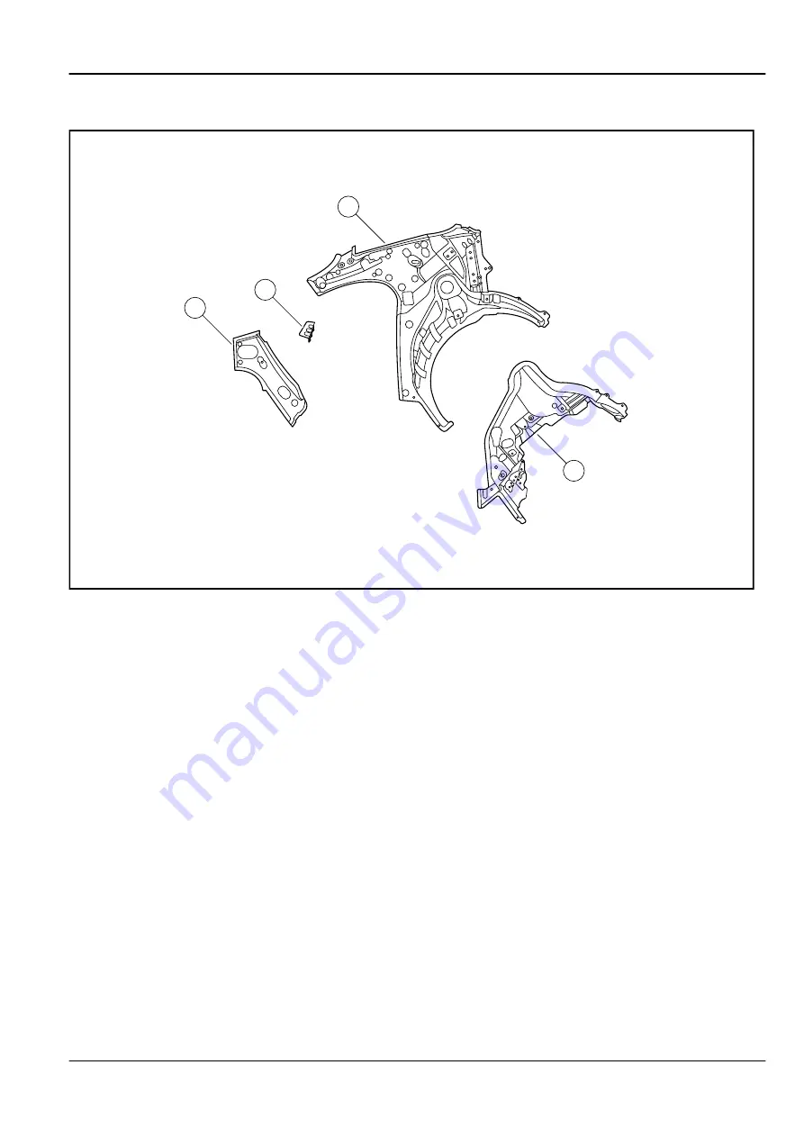
12.12.3.12 Body Rear Pillars (Sedan)

2

4

1

3

FE12-1040b

Legend

1. Left Rear Pillar Inner Panel Assembly
2. Left Rear Pillar Reinforcement Panel
3. Left Rear Wheelhouse Panel

4. Left Rear Door Lock Mounting Panel

Body, Sheet Metal and Painting

Collision Repair

12-149

EC718/EC718RV EC715/EC715RV  10/2009

Summary of Contents for EC715 2009

Page 1: ...ostic and service information 2009 Geely Automotive Co Ltd All rights reserved Information as of the date of October 2009 Without written permission from Geely Automotive Co Ltd any form or means including but not limited to electronic duplicating photocopying scanning and recording of copying storing or distribution of any part or the whole manual is not allowed ...

Page 2: ...ation in this manual is based on the latest products available at the time of publishing The specifications and the repair procedures may change without prior notice It is recommended that you contact Geely Automotive Co Ltd to obtain the information about the products part numbers or special tools referred in this manual If there are any omissions or mistakes please contact Geely Automotive Co Lt...

Page 3: ...to commencing repair ensure the safety of technical personnel and prevent personal injury or damage to customer vehicles When replacing parts please use parts approved by Geely Automotive Co Ltd with the same part numbers Do not use inferior parts To reduce the risk of causing bodily harm and to reduce the possibilities of causing vehicle damage please strictly follow all the warnings and notes It...

Page 4: ......

Page 5: ...4G15 D 2 823 2 17 Exhaust System JL4G15 D 2 835 2 18 Engine Cooling System JL4G15 D 2 837 2 19 Lubrication System JL4G15 D 2 854 2 20 Ignition System JL4G15 D 2 856 2 21 Starting Charging System JL4G15 D 2 871 3 Transmission Drive Axle 3 1 3 1 Warnings and Notices 3 3 3 2 Clutch System 3 4 3 3 Manual Transmission 3 27 Part Three Chassis 4 Suspension System 4 1 4 1 Warnings and Notices 4 3 4 2 Fron...

Page 6: ...7 11 14 Reverse Radar 11 461 11 15 Instrument Cluster 11 488 11 16 Cigarette Lighter 11 499 11 17 Data Communication System 11 513 Part Five Body 12 Body Sheet Metal and Painting 12 1 12 1 Warnings and Notices 12 4 12 2 Body Front End 12 5 12 3 Body Rear End 12 13 12 4 Bumpers 12 27 12 5 Doors 12 38 12 6 Frame and Underbody 12 44 12 7 Seats 12 53 12 8 Instrument Panel Gages and Console 12 61 12 9 ...

Page 7: ... 6 Health and Safety 1 28 1 6 1 Description and Operation 1 28 1 6 1 1 Description 1 28 1 6 1 2 Acid and Alkali 1 28 1 6 1 3 Airbag 1 28 1 6 1 4 Air Conditioning Refrigerant 1 29 1 6 1 5 Adhesives and Sealants 1 29 1 6 1 6 Engine Coolant 1 29 1 6 1 7 Asbestos 1 29 1 6 1 8 Battery Acid Fluid 1 29 1 6 1 9 Brake Fluid 1 29 1 6 1 10 Chemical Materials 1 29 1 6 1 11 Dust 1 30 1 6 1 12 Electrical Shock ...

Page 8: ... 1 11 Water Leaks 1 69 1 11 1 Description and Operation 1 69 1 11 1 1 Diagnostic Information and Procedures 1 69 1 11 1 2 Repair 1 69 1 12 Special Tools 1 71 1 12 1 Special Tools and Equipment 1 71 1 12 1 1 Power Train Special Tools 1 71 1 12 1 2 Chassis and Body Special Tools 1 76 1 2 Table of Contents Vehicle Overview EC718 EC718RV EC715 EC715RV 10 2009 ...

Page 9: ...e coolant lubricants or other fluid leak Definition of Note Note states the importance of a diagnostic procedure or the need The purpose of the Note is as following Clarify the procedures Provide additional information for completing a procedure Clarify the recommended procedures for operational reasons Provide help for technicians to complete the repair more efficiently Provide experience to tech...

Page 10: ... may cause damage to the brake pipes and brake system resulting in personal injury Breathing R 134a Warning Warning Avoid breathing the A C Refrigerant 134a R 134a and the lubricant vapor or the mist Exposure may irritate the eyes nose and throat Work in a well ventilated area In order to remove R 134a from the A C system use service equipment that is certified to meet the requirements of SAEJ2210...

Page 11: ...roper reconnection if not lubricated Fuel Storage Warning Warning Do not drain the fuel into an open container Never store the fuel in an open container due to the possibility of a fire or an explosion Fuel Vapors in Evaporative Emission Components Warning Warning Do not breathe the air through the EVAP component tubes or hoses The fuel vapors inside the EVAP components may cause personal injury G...

Page 12: ... SIR Warning Warning This vehicle is equipped with a Supplemental Inflatable Restraint SIR System Failure to follow the correct procedure could cause the following conditions Airbag deployment Personal injury Unnecessary SIR system repairs Warning In order to avoid the above conditions observe the following guidelines Refer to SIR Component Views in order to determine if you are performing service...

Page 13: ...to prevent damage to the brake line Brake Fluid Effects on Paint and Electrical Components Notice Notice Avoid spilling brake fluid onto painted surfaces electrical connections wiring or cables Brake fluid will damage painted surfaces and cause corrosion to electrical components If any brake fluid comes in contact with painted surfaces immediately flush the area with water If any brake fluid comes...

Page 14: ...pecifications when installing fasteners in order to avoid damage to parts and systems Fuel Pressure Notice Notice Do not allow the fuel pressure to exceed the specified value because damage to the fuel pressure regulator or the fuel pressure gage may result Handling Electrostatic Discharge Sensitive Parts Notice Notice Electrostatic discharge ESD can damage many solid state electrical components E...

Page 15: ...o not touch the connector pins or soldered components on the circuit board in order to prevent possible electrostatic discharge ESD damage to the PCM Power Steering Hose Disconnected Notice Notice Do not start the vehicle with any power steering gear inlet or outlet hoses disconnected When disconnected plug or cap all openings of components Failure to do so could result in contamination or loss of...

Page 16: ...he connector terminal Do not visually choose the terminal test adapter because some connector terminal cavities may appear larger than the actual terminal in the cavity Using a larger terminal test adapter will damage the terminal Using Proper Power Steering Fluid Notice Notice When adding fluid or making a complete fluid change always use DEXRONⅢ Failure to use the proper fluid will cause hose an...

Page 17: ...the bottom of the oil pan after a few minutes 2 Pull out the dipstick 3 Wipe clean the dipstick and then insert it back 4 Pull out the dipstick and inspect the oil level 5 If necessary add engine oil so that the oil level maintained between MIN minimum line and the MAX maximum line Do not fill an excessive amount of engine oil otherwise it may cause damage to the engine 6 After reading the engine ...

Page 18: ...s of wear or lack of lubrication Inspect whether power steering system pipe and hose is connected properly and whether there are catching leakage cracks or scratches Clean the drive axle jacket and seals and inspect for damage cracking or leakage if necessary replace the seals Exhaust System Inspect the entire exhaust system including the catalytic converter Inspect vehicle body near the exhaust s...

Page 19: ...gine coolant is too dirty or rusty drain the engine coolant Flush the engine cooling system and refill the new engine coolant Maintain an appropriate concentration of engine coolant in order to ensure the correct antifreeze anti boiled anti corrosion properties and engine operating temperature Check the hoses Replace the cracked expanded or aged hoses Inspect fastening clip cleaning radiators and ...

Page 20: ... contact the catalytic converter the brake pipes or the fuel lines If such contact occurs vehicle damage or unsatisfactory vehicle performance may result Before you begin any lifting procedure be sure the vehicle is on a clean hard level surface Be sure all the lifting equipment meets weight standards and is in good working order Be sure all the vehicle loads are equally distributed and secure If ...

Page 21: ...Vehicle Jacking Locations FE01 0001b Vehicle Overview Lifting and Jacking the Vehicle 1 15 EC718 EC718RV EC715 EC715RV 10 2009 ...

Page 22: ...ms must not contact the rocker panels to the outside of the side frame rails or the floor pan Position the rear hoist pads as follows Under the junction between the rear frame rails and the side frame rails 1 16 Lifting and Jacking the Vehicle Vehicle Overview EC718 EC718RV EC715 EC715RV 10 2009 ...

Page 23: ...pads and arms must not contact the rocker panels the front mud guards or the floor pan Position the front hoist pads as follows Under the front frame box section Vehicle Overview Lifting and Jacking the Vehicle 1 17 EC718 EC718RV EC715 EC715RV 10 2009 ...

Page 24: ...rease Universal Lithium Grease Engine Coolant Comply with SH0521 the freezing point 40 C 40 ºF Engine Oil Comply with GB11121 API quality grade SJ class exports to the EU SL class viscosity SAE 5W 30 10W 30 10W 40 15W 40 Floor Shift Linkage Grease Universal Lithium Grease Hood and Truck Hinges Fuel Filler Door Hinges Luggage Compartment Door Hinge Universal Lithium Grease Manual Transmission Fluid...

Page 25: ...Service Note I Inspect and adjust or replace as needed R Replace 1 Inspect valve noise and engine vibration Adjust if necessary 2 80 000 km or 48 months later every 20 000 km or 12 months check again 3 Inspect radiators and condensers for blockage by leaves dust or insects Clean hose connections 4 80 000 km or 48 months later every 20 000 km or 12 months check again 5 Replace after first 60 000 km...

Page 26: ...Battery I I I I I I I I I I I I I I I I I 12 Fuel and Exhaust Systems 11 Fuel Filter R R R R 12 Air Filter I R I R I R I R I R I R I R I R I I 6R 24 13 Fuel Tank Cap Fuel Pipes Fuel Evaporation Control Valve 4 I I I I 24 14 Evaporative Emission Canister I I I 60 Chassis and Body 15 Brake Pedal and Park Brake I I I I I I I I I I I I I I I I I 6 16 Brake Pads and Brake Disc I I I I I I I I I I I I I...

Page 27: ... R R R 12 28 Air Conditioning System Refrigerant I I I I I I I I 12 1 4 2 3 Harsh Driving Condition Service Schedule Harsh driving conditions are listed in the following table Increase the frequency of service For unlisted conditions refer to the1 4 2 2 Normal Driving Condition Service Schedule Inspection Items Time or Odometer Reading A 1 Driving on uneven muddy or melting snow road Check brake p...

Page 28: ...ds and brake disc Every 5 000 km or 6 months Every 5 000 km or 6 months Every 5 000 km or 6 months Every 5 000 km or 3 months B 4 Frequent high speed driving for more than 2h 80 of the maximum vehicle speed Replace Transmission Fluid Every 20 000 km or 12 months B 5 Extended period of idle low speed and frequent acceleration and deceleration such as a driving training vehicle Replace engine oil Re...

Page 29: ...ervice Inspect the disc brake pads every 7 500 km or 7 months Double check the thickness of brake pads If the brake pads can not last until the next scheduled service they should be replaced Check the brake fluid tank lid vent to ensure that there is no dirt and the path is unblocked Differential Service Inspect differential oil every 20 000 km or 12 months Replace differential oil every 40 000 km...

Page 30: ...FE01 0004b Note For Directional tires carry out rotation as shown below 1 24 Maintenance Vehicle Overview EC718 EC718RV EC715 EC715RV 10 2009 ...

Page 31: ...e tire and wheel assemblies Refer to 4 4 5 1Wheel Replacement 6 Remove the safety stands 7 Lower the vehicle 8 Check and adjust the tire inflation pressure Vehicle Overview Maintenance 1 25 EC718 EC718RV EC715 EC715RV 10 2009 ...

Page 32: ...a Link Connector ECM Engine Control Module ECT Engine Coolant Temperature Sensor EVAP Evaporative Emission Canister Purge Solenoid Valve HO2S Heated Oxygen Sensor IAC Idle Air Control IP Cluster Instrument Panel Cluster KS Knock Sensor TPS Throttle Position Sensor VSS Vehicle Speed Sensor PAID Rear Park Aid Module HVAC Heating Ventilation Air Conditioning HECU Hydraulic Electronic Control Unit IMM...

Page 33: ...tion 2 2 2 2 2 2 2 2 2 2 2 2 1 5 3 4 2 FE01 0023b Legend 1 Arrow 2 Motion or Direction 3 Rotation Direction of the Arrow 4 Part Number 5 Enlarged Area Vehicle Overview Service Information System 1 27 EC718 EC718RV EC715 EC715RV 10 2009 ...

Page 34: ...This propellant is stored in airtight sealed components and fills the airbag when the airbag is deployed It is prohibited to open airbags during maintenance as this would lead to dangerous contact with the propellant If the gas containers happen to break wear full protective clothing when handling the overflow materials After deploying airbags wear safety goggles and gloves when handling the airba...

Page 35: ...glycol may produce steam Avoid inhaling the vapor After direct contact with engine coolant through the skin directly absorbed dose may reach toxic or harmful dose If swallowing engine coolant it may be life threatening The person must be taken to hospital and seek medical treatment immediately These products must not be used in conjunction with the ordinary food processing or connected with the dr...

Page 36: ...entrations of gas may still have the possibility of poisoning or hurt 1 6 1 11 Dust Powder and dust may be irritating harmful or toxic Avoid inhaling the chemical material powder stirred up dry friction If the ventilation is poor wear a breathing mask protective equipment in order to prevent inhaling dust Flammable fine dust may cause explosion Keep them away from an explosion or a fire 1 6 1 12 E...

Page 37: ...l Remember Do not inhale vapor or spray These materials must be used at a well ventilated place or with respiratory protection measures Do not immediately remove the mask after spraying Wait for the steam and the spray completely dissipated Uncured components and cured foam will produce toxic and harmful gases during the bubble operation Unless the steam and the spray has been completely removed d...

Page 38: ...the skin Used Engine Oil Prolonged and repeated contact with mineral oils will cause the loss of the natural skin oils causing dry irritation and skin diseases In addition used engine oil is very likely to contain harmful substances that can lead to skin cancer Make sure use the skin protective equipment and be equipped with adequate washing facilities Do not be used engine oil as a lubricant or a...

Page 39: ...7187 5 32 0 15625 3 96875 11 64 0 171875 4 36562 3 16 0 1875 4 7625 13 64 0 203125 5 15937 7 32 0 21875 5 55625 15 64 0 234375 5 95312 1 4 0 25 6 35 17 64 0 265625 6 74687 9 32 0 28125 7 14375 19 64 0 296875 7 54062 5 16 0 3125 7 9375 21 64 0 328125 8 33437 11 32 0 34375 8 73125 23 64 0 359375 9 12812 3 8 0 375 9 525 25 64 0 390625 9 92187 13 32 0 40625 10 31875 27 64 0 421875 10 71562 7 16 0 4375...

Page 40: ... 66875 43 64 0 671875 17 06562 11 16 0 6875 17 4625 45 64 0 703125 17 85937 23 32 0 71875 18 25625 47 64 0 734375 18 65312 3 4 0 75 19 05 49 64 0 765625 19 44687 25 32 0 78125 19 84375 51 64 0 796875 20 24062 13 16 0 8125 20 6375 53 64 0 828125 21 03437 27 32 0 84375 21 43125 55 64 0 859375 21 82812 7 8 0 875 22 225 57 64 0 890625 22 62187 29 32 0 90625 23 01875 59 64 0 921875 23 41562 15 16 0 937...

Page 41: ...km Area Square Inch in2 645 2 Square Millimeter mm2 Square Inch in2 6 45 Square Centimeter cm2 Square Feet ft2 0 0929 Square Meter m2 Square Yard yd2 0 8361 Square Meter m2 Volume Cubic Inch in3 16 387 0 Cubic Millimeter mm3 Cubic Inch in3 16 387 Cubic Centimeter cm3 Pint pt 0 5680 L L Quart quart 0 9464 Cubic Meter m3 Gallon Vsgal 3 7854 Cubic Meter m3 Cubic Yard yd3 0 764 Cubic Meter m3 Weight P...

Page 42: ...ss inch ft in ft2o 0 2488 KPa kPa Pound Square Inch lb in2 6 895 KPa kPa Energy Power US English Thermal Unit Btu 1 055 0 Joules 1 Joule 1 watt second J 1J 1ws lb ft lb ft 1 3558 Joule 1 Joule 1 watt second J 1J 1ws Kilowatt Hour kWh 3 600 000 0 Joule 1 Joule 1 watt second J 1J 1ws Light Foot Candle fc 10 764 lm m 2 lm m2 Speed Mile Hour mil h 1 6093 Km Hour km h Temperature F 32 5 9 C F 9 5 C 32 ...

Page 43: ...fications 1 8 1 Specifications 1 8 1 1 Body Size Front View Sedan Front Wheel Distance 1 502 mm 59 in Body Width 1 789 mm 70 in FE01 0007b Vehicle Overview Vehicle Specifications 1 37 EC718 EC718RV EC715 EC715RV 10 2009 ...

Page 44: ...Front View Hatchback Front Wheel Distance 1 502 mm 59 in Body Width 1 789 mm 70 in FE01 0007c 1 38 Vehicle Specifications Vehicle Overview EC718 EC718RV EC715 EC715RV 10 2009 ...

Page 45: ...ody Length 4 635 mm 182 in Approach Angle 17 10 46 Wheel Base 2 650 mm 104 in Departure Angle 21 Minimum Clearance 167 mm 6 in FE01 0008b Vehicle Overview Vehicle Specifications 1 39 EC718 EC718RV EC715 EC715RV 10 2009 ...

Page 46: ...ack Body Length 4 397 mm 173 in Approach Angle 16 Wheel Base 2 650 mm 104 in Minimum Clearance 167 mm 6 in Departure Angle 27 FE01 0008c 1 40 Vehicle Specifications Vehicle Overview EC718 EC718RV EC715 EC715RV 10 2009 ...

Page 47: ...Rear View Sedan Rear Wheel Distance 1 483 mm 58 in Body Height 1 480 mm 58 in FE01 0009b Vehicle Overview Vehicle Specifications 1 41 EC718 EC718RV EC715 EC715RV 10 2009 ...

Page 48: ...Rear View Hatchback Rear Wheel Distance 1 492 mm 58 in Body Height 1 470 mm 57 in FE01 0009c 1 42 Vehicle Specifications Vehicle Overview EC718 EC718RV EC715 EC715RV 10 2009 ...

Page 49: ...Metric bolts shown above the intensity level increases with the number Vehicle Fasteners Specifications Part name Application Specifications Torque Range Metric Nm US English lb ft Hex Head Bolt and Washer Assembly Connecting ECM and ECM Bracket M6 20 7 9 5 2 6 6 Hexagon Flange Bolts Fixed ECM Bracket M6 20 8 10 5 9 7 4 Hex Head Bolt and Washer Assembly Speed Sensor M6 20 7 9 5 2 6 6 Hex Head Bolt...

Page 50: ...ing Washer and Washer Assembly Engine Cooling System M6 1 25 20 8 12 5 9 8 9 Hex Head Bolt Spring Washer and Washer Assembly Engine Cooling System M8 1 25 20 22 26 16 2 19 2 Hexagon Flange Bolts Engine Cooling System M8 1 25 20 20 26 14 8 19 2 Hex Head Bolt Spring Washer and Washer Assembly Exhaust M12 1 25 45 47 57 34 7 42 Hexagon Flange Nut Exhaust M12 47 57 34 7 42 Hexagon Nut With a Flower Sha...

Page 51: ... 42 Hexagon Flange Bolts Power Train Suspension M10 1 25 22 47 57 34 7 42 Hexagon Flange Bolts Power Train Suspension M10 1 25 45 50 60 36 9 44 3 Hexagon Flange Bolts Power Train Suspension M10 1 25 65 70 86 51 6 63 4 Hexagon Flange Bolts Power Train Suspension M10 1 25 90 47 57 34 7 42 Hexagon Flange Bolts Power Train Suspension M8 1 25 16 47 57 34 7 42 Hexagon Flange Nut Power Train Suspension M...

Page 52: ...16 26 11 8 19 2 Wheel Nut Wheel Rim and Brake M12 105 115 77 4 84 8 Hex Head Bolt and Washer Assembly Wheel Speed Sensor Wiring Harness M6 18 19 14 Hex Head Bolt Spring Washer and Washer Assembly Single Tube Clip M6 30 19 14 Hexagon Bolt Spring Washer and Washer Assembly HECU Controller Assembly M8 20 35 25 8 Bolt and Washer Assembly Steering Column Separation Stand M8 30 35 25 8 Hexagon Flange Bo...

Page 53: ... Body and The Rear Axle Assembly M12 135 130 160 95 9 118 Hexagon Flange Nut Body and The Shock Absorber M10 75 85 55 3 62 7 Hexagon Flange Nut Shock Absorber and The Rear Axle M14 135 165 99 6 121 7 Slotted Hex Flange Nut Body and The Rear Axle Assembly M12 130 160 95 9 118 Hexagon Flange Bolts Body and The Shock Absorber M10 25 75 85 55 3 62 7 Hexagon Flange Nut Stabilizer Clips With The Front S...

Page 54: ...ing Knuckle M14 131 159 96 6 117 3 Hexagon Flange Bolt Control Arm Welding Assembly and Ball Pin Assembly M12 16 131 159 96 6 117 3 Hexagon Flange Nut Control Arm Welding Assembly and Ball Pin Assembly M12 131 159 96 6 117 3 Ⅰ Type Non metallic Insert Hex Lock Nut Shock Absorber Piston Rod M14 60 80 44 4 59 2 Ⅰ Type Non metallic Insert Hex Lock Nut Shock Absorber Piston Rod M14 60 80 44 4 59 2 Hex...

Page 55: ...olt Right Front Door Assembly M8 23 23 26 17 19 2 Hexagon Flange Bolt Left Rear Door Assembly M8 23 23 26 17 19 2 Hexagon Flange Bolt Right Rear Door Assembly M8 23 23 26 17 19 2 Cross Slot Countersunk Head Screw Left Rear Door Assembly M5 8 1 3 0 7 2 2 Cross Slot Countersunk Head Screw Right Rear Door Assembly M5 8 1 4 0 7 3 Hexagon Flange Bolt Left Rear Door Assembly M6 10 9 12 6 6 8 9 Hexagon F...

Page 56: ...t Instrument Panel Cluster Assembly M8 12 8 12 Cross Slot Pan Head Screw Instrument Panel Cluster Assembly ST4 8 16 4 6 3 4 4 Cross Slot Pan Head Screw Instrument Panel Assembly ST4 2 16 4 6 3 4 4 Cross Slot Countersunk Head Screw Storage Lid on Instrument Panel assembly ST4 2 16 4 6 3 4 4 Cross Slot Pan Head Screw Steering Column Decorative Cover M4 12 4 6 3 4 4 Plastic Clip Left Front Door Trim ...

Page 57: ...oor Trim Panel Components ST4 2 9 5 5 5 6 3 4 1 4 7 Cross Slot Pan Head Screw and Washer Assembly Right Front Door Trim Panel Components ST4 2 9 5 5 5 6 3 4 1 4 7 Cross Slot Pan Head Screw and Washer Assembly Left Rear Door Trim Panel Components ST4 2 9 5 5 5 6 3 4 1 4 7 Cross Slot Pan Head Screws and Washer Assembly Right Rear Door Trim Panel Components ST4 2 9 5 5 5 6 3 4 1 4 7 Cross Slot Counte...

Page 58: ...rim Panel Assembly ST4 2 16 5 6 3 4 4 7 Hexagon Flange Nut Front Bumper M6 3 5 5 5 3 4 1 Cross Slot Hexagon Head Screw and Washer Assembly Front bumper Left Right Mounting Brackets ST6 3 19 3 5 5 5 3 4 1 Cross Slot Hexagon Head Screw and Washer Assembly Front Bumper ST4 8 16 3 5 5 5 3 4 4 Cross Slot Hexagon Head Bolt and Spring Washer Assembly Front Bumper M6 16 8 10 5 9 7 4 Cross Slot Hexagon Hea...

Page 59: ... Buckle Ventilation Assembly Φ5 Plastic Clip Left Rocker Panel 20 9 Plastic Clip Right Rocker Panel 20 9 Plastic Clip Engine Bottom Left Shield 8 2 8 2 Plastic Clip Engine Bottom Right Shield 8 2 8 2 Plastic Clip Left Front Fender 8 2 8 2 Plastic Clip Right Front Fender 8 2 8 2 Plastic Clip Left Rear Wheelhouse Liner 8 2 8 2 Plastic Clip Right Rear Wheelhouse Liner 8 2 8 2 Cross Slot Hexagon Head ...

Page 60: ... Lock M6 12 22 29 16 3 21 5 Hexagon Countersunk Head Screw Door Lock M8 16 22 29 16 3 21 5 Hexagon Flange Nut Outside Rear view Mirror M6 8 5 9 Hexagon Flange Bolt Sunroof Assembly M6 12 7 9 5 2 6 7 Hexagon Flange Nut Door Window Assembly M6 7 9 5 2 6 7 Hexagon Flange Nut Door Window Assembly M6 10 7 9 5 2 6 7 Hexagon Flange Bolt Door Assembly M8 16 24 26 17 8 19 2 Hexagon Head Bolt and Washer Ass...

Page 61: ...2 3 Hexagon Head Bolt Spring Washer and Washer Assembly Radio Antenna M6 16 8 11 5 9 8 1 Hexagon Head Bolt Spring Washer and Washer Assembly Driver seat M6 16 8 11 5 9 8 1 Hexagon Head Bolt Spring Washer and Washer Assembly Shift Control M6 16 8 11 5 9 8 1 Cross Slot Head Screw Instrument Panel ST4 8 13 2 4 1 5 3 Cross Slot Pan Head Screw and Washer Assembly Instrument Panel ST4 2 9 5 2 4 1 5 3 He...

Page 62: ...ross Slot Countersunk Head Screw Air Conditioning Control Panel Assembly M5 16 7 8 5 2 5 9 Hexagon Flange Nut Suction Hose Bracket Assembly M6 7 8 5 2 5 9 Hexagon Head Bolt and Washer Assembly Left Right Headlamp Assembly M6 20 3 5 2 2 3 7 Hexagon Flange Nut M5 Left Right Headlamp Assembly M5 3 5 2 2 3 7 Cross Slot Pan Head Screws and Washer Assembly Left Right Front Fog Lamp Assembly M6 16 3 5 2 ...

Page 63: ...6 20 6 8 9 2 5 1 6 8 Hexagon Flange Nut Steering Wheel and Steering Column M12X1 2 41 49 30 2 36 1 Hexagon Flange Bolt Passenger Airbag and Instrument Panel Beam M6 16 7 9 5 2 6 6 Hexagon Head Bolt Spring Washer and Washer Assembly Curtain Airbag M6 16 7 10 5 2 7 4 Side Airbag M6 16 4 4 5 3 0 3 2 M6 Bolt Non Standard Driver Airbag M6 16 8 5 9 5 6 3 7 0 Hexagon Head Bolt and Washer Assembly Side Co...

Page 64: ...Vehicle Identification Number VIN Description The vehicle identification number is consisted of World s manufacturer identification code WMI vehicle description section VDS and vehicle parts instructions VIS three parts 17 bit as shown below WMI VIS VDS Part One Part Two Part Three Region Country Manufacturing Plant Vehicle Type Check Year Assembly Plant Production Number FE01 0021b Vehicle identi...

Page 65: ...git of vehicle identification number of which L6T Zhejiang Geely Automotive Co Ltd LJU Shanghai Huapu Automotive Co Ltd LB3 Zhejiang Haoqing Automotive Manufacturing Co Ltd The Fourth Digit Serial Number Vehicle Type Code 1 Chassis Non complete Vehicle 0 2 Truck 1 3 Special Purpose Vehicle 5 4 Bus 6 5 Passenger Car Wheelbase 2 5 m 7 6 Wheelbase 2 5 2 7 m 8 7 Wheelbase 2 7 m 9 The Fifth Digit Passe...

Page 66: ...1 5 2 4 1 5 1 7 3 5 1 7 1 9 4 6 1 9 2 1 5 7 2 1 6 8 Diesel 1 3 A 9 1 3 2 5 B 10 2 5 C 11 Rear Gasoline 1 L 12 Gasoline 1 1 1 3 M 13 1 3 N 14 Diesel 1 3 T 15 1 3 2 5 U 16 2 5 V Serial Number Power Source Engine Displacement L Code 1 Hybrid 1 3 E 2 1 3 3 0 F 3 Dual Fuel Petrol Liquefied Petroleum Gas LPG 1 3 G 4 1 3 3 0 H 5 Gasoline Compressed Natural Gas CNG 1 3 J 6 1 3 3 0 K 1 60 Vehicle Identific...

Page 67: ...T 12 Sedan 4 Door 1 U 13 Non Load Type Hatchback 2 Door 6 14 Hatchback 5 Door 7 15 Hatchback 4 Door 8 16 Sedan 4 Door 9 17 Hatchback 2 Door 1 F 18 Hatchback 5 Door 1 G 19 Hatchback 4 Door 1 H 20 Sedan 4 Door 1 J 21 Hatchback 2 Door 1 L 22 Hatchback 5 Door 1 M 23 Hatchback 4 Door 1 N 24 Sedan 4 Door 1 P Note 1 indicates YES indicates NO Cabin Body Type Table Serial Number Cabin Type Body Type Code ...

Page 68: ...ble 11 Repeat in a 30 year cycle Year Code Year Code Year Code Year Code 2001 1 2011 B 2021 M 2031 1 2002 2 2012 C 2022 N 2032 2 2003 3 2013 D 2023 P 2033 3 2004 4 2014 E 2024 R 2034 4 2005 5 2015 F 2025 S 2035 5 2006 6 2016 G 2026 T 2036 6 2007 7 2017 H 2027 V 2037 7 2008 8 2018 J 2028 W 2038 8 2009 9 2019 K 2029 X 2039 9 2010 A 2020 L 2030 Y 2040 A The 11th Digit It is used to distinguish differ...

Page 69: ... Brand Geely Meiri Engine Type JLƔ4G18 D Engine Rated Power 102KW Engine Displacement 1792mL Model MR7180 Number of Passengers 5 Mass 1610kg Manufacturing Date 1 2 7 8 9 3 4 5 6 FE01 0014b 1 Vehicle Identification Number VIN 2 Brand 3 Category of Vehicle 4 Number of Passenger 5 Vehicle Weight 6 Date of Manufacture 7 Engine Model 8 Engine Power 9 Engine Displacement China Zhejiang Geely Automotive ...

Page 70: ...ode 18 Engine Displacement 000009D Serial Number The Engine Serial Number Location FE01 0017b The engine serial number is stamped on the left hand side at the rear of the engine cylinder block near engine fly wheel 1 9 1 6 Manual Transmission Serial Number and its Location Manual Transmission Serial Number Label JL S170B 001 Zhejiang Geely Automotive Co Ltd Product Certificate Product Model JL S17...

Page 71: ...Manual Transmission Drive Axle Identification Number Location FE01 0019b Vehicle Overview Vehicle Identification Number 1 65 EC718 EC718RV EC715 EC715RV 10 2009 ...

Page 72: ...leak location Use masking tapes for temporary repair Continue the road test to confirm whether all the wind noise has been eliminated or there are still leaks at other parts Return to workshop after having identified all the leaks during road test Use specialized methods and sealing material to carry out permanent repair Vibration Most of the high speed vibrations are due to lack of wheel dynamic ...

Page 73: ...engine is cold Check the manual shift assembly Switch between gears and verify the squeak Remove the floor console shift lever lubricate it and install it 1 10 1 2 Repair Wind Noise Air Sound External Wind Noise The wind noise leak repair is very similar to that of water leaking Refer to 1 11 1 1 Diagnostic Information and Procedures The actual repair procedures depend on the type of seals Vibrati...

Page 74: ...elative motion To repair abnormal sound there are three ways Tighten the fasteners so that there is no relative motion Separate parts so that components do not contact Isolated parts so that there is no abnormal noise when parts moving Even low friction surfaces can be used to eliminate viscosity between the sliding parts 1 68 Noise Vibration and Abnormal Sound Vehicle Overview EC718 EC718RV EC715...

Page 75: ...s If the water leaks appears in the door trunk door or window it is not necessary that the water leaks is created by sealing strip Adjust these parts might correct the water leaks Testing With A Water Hose Note Do not use water hose with a nozzle 1 Let an assistant inside the vehicle to confirm the exact location of water leaks 2 Start testing from the bottom of the window or the windshield 3 Move...

Page 76: ...3 If it is fixed windows side leakage use a dedicated seam adhesive to repair or replace the windshield 1 70 Water Leaks Vehicle Overview EC718 EC718RV EC715 EC715RV 10 2009 ...

Page 77: ...ol Number Description 1 FE01 2001b GL201 001 Input Shaft Holding Fixture 2 FE01 2002b GL201 002 Input Shaft Seal Installer 3 FE01 2003b GL201 003 Input and Output Shaft Parts Installer 4 FE01 2004b GL201 004 Transmission Input Shaft Bearing Remover Vehicle Overview Special Tools 1 71 EC718 EC718RV EC715 EC715RV 10 2009 ...

Page 78: ...emover 6 FE01 2006b GL201 006 Output Shaft Bearing Cup Installer 7 FE01 2007b GL201 007 Output Shaft Bearing Remover 8 FE01 2008b GL201 008 Output Shaft Adjuster 9 FE01 2009b GL201 009 Differential Clutch Housing Oil Seal Remover 1 72 Special Tools Vehicle Overview EC718 EC718RV EC715 EC715RV 10 2009 ...

Page 79: ...ousing Oil Seal Remover 11 FE01 2011b GL201 011 Differential Bearing Remover 12 FE01 2028b GL201 014 Manual Shift Assembly Oil Seal Installer 13 FE01 2014b GT301 002 Driver Handle 14 FE01 2015b GT301 006 Valve Oil Seal Remover Vehicle Overview Special Tools 1 73 EC718 EC718RV EC715 EC715RV 10 2009 ...

Page 80: ...al Installer 16 FE01 2017b GT301 009 Valve Tube Remover 17 FE01 2018b GT301 013 Crankshaft Front Oil Seal Installer 18 FE01 2019b GT301 015 Crankshaft Rear Oil Seal Installer 19 FE01 2020b GT301 016 Piston Pin Remover 1 74 Special Tools Vehicle Overview EC718 EC718RV EC715 EC715RV 10 2009 ...

Page 81: ...tch Installer 21 FE01 2022b GT301 018 Camshaft Positioning Tool 22 FE01 2029b GT301 020 Camshaft Locking Tool 23 FE01 2023b GT301 021 Flywheel Holding Tool 24 FE01 2024b GT301 022 Timing Chain Retention Tool Vehicle Overview Special Tools 1 75 EC718 EC718RV EC715 EC715RV 10 2009 ...

Page 82: ...tion Tool Number Description 1 FE01 2025b GL401 001 Front Axle Wheel Hub Bearing Remover 2 FE01 2026b GL401 002 Drive Shaft Ball Bearing Remover 3 FE01 2027b GL401 003 Rear Axle Sleeve Remover 1 76 Special Tools Vehicle Overview EC718 EC718RV EC715 EC715RV 10 2009 ...

Page 83: ...TC Code DTC list 2 50 2 2 7 8 DTC Fail Safe Table 2 54 2 2 7 9 Data Stream List 2 57 2 2 7 10 Action Test Table 2 62 2 2 7 11 DTC Code Index 2 64 2 2 7 12 DTC P0010 P2088 P2089 2 69 2 2 7 13 DTC P000A P0012 2 73 2 2 7 14 DTC P0016 2 77 2 2 7 15 DTC P0030 P0031 P0032 P0053 2 79 2 2 7 16 DTC P0036 P0037 P0038 P0054 2 83 2 2 7 17 DTC P0105 P0106 P0107 P0108 2 87 2 2 7 18 DTC P0112 P0113 2 93 2 2 7 19...

Page 84: ...noperative 2 239 2 3 7 5 Fuel Gage Inaccurate 2 243 2 3 7 6 Surge diagnostic 2 243 2 3 7 7 Fuel Pressure Testing Procedure 2 247 2 3 8 Removal and Installation 2 249 2 3 8 1 Fuel Pressure Release Procedure 2 249 2 3 8 2 Fuel Filter Replacement 2 249 2 3 8 3 Fuel Pump Assembly Replacement 2 250 2 3 8 4 Fuel Level Sensor Replacement 2 254 2 4 Auxiliary Emission Control JL4G18 D 2 257 2 4 1 Specifica...

Page 85: ...st Valves Lifter Specifications Table 2 302 2 6 1 4 Intake and Exhaust Valves Lifter Selection Table 2 304 2 6 2 Description and Operation 2 306 2 6 2 1 Description and Operation 2 306 2 6 3 System Working Principle 2 307 2 6 3 1 System Working Principle 2 307 2 6 4 Component Locator 2 309 2 6 4 1 Component Locator 2 309 2 6 5 Disassemble View 2 310 2 6 5 1 Cylinder Head Covers 2 310 2 6 5 2 Camsh...

Page 86: ... 2 7 5 Diagnostic Information and Procedures 2 438 2 7 5 1 Diagnostic Description 2 438 2 7 5 2 Visual Inspection 2 438 2 7 5 3 Exhaust System Blockage 2 438 2 7 5 4 Exhaust System Leakage 2 438 2 7 5 5 Exhaust System Noise 2 439 2 7 5 6 Exhaust System Repair Notes 2 439 2 7 6 Removal and Installation 2 441 2 7 6 1 Exhaust Manifold Replacement 2 441 2 7 6 2 Three way Catalytic Converter Replacemen...

Page 87: ...ng Specifications 2 517 2 10 1 2 Ignition System Specification 2 517 2 10 2 Description and Operation 2 518 2 10 2 1 Description and Operation 2 518 2 10 3 System Working Principle 2 519 2 10 3 1 System Working Principle 2 519 2 10 4 Component Locator 2 520 2 10 4 1 Component Locator 2 520 2 10 5 Disassemble View 2 521 2 10 5 1 Ignition Cylinder Assembly Disassemble View 2 521 2 10 6 Schematic 2 5...

Page 88: ...2 Components Descriptions 2 587 2 12 3 System Working Principle 2 593 2 12 3 1 Electronic Throttle Body ETC Working Principle 2 593 2 12 3 2 ECM Controlled Fuel Supply System 2 594 2 12 3 3 ECM Controlled Ignition System 2 595 2 12 3 4 Electronic Throttle Body Function Restrictions 2 596 2 12 3 5 Idle Speed Control 2 597 2 12 3 6 Knock Control 2 598 2 12 3 7 Air Conditioning Switch Off Control 2 5...

Page 89: ...stallation 2 795 2 12 8 1 Acceleration Pedal Replacement 2 795 2 13 Fuel System JL4G15 D 2 797 2 13 1 4G15 D Fuel System Overview 2 797 2 13 1 Diagnostic Information and Procedures 2 798 2 13 1 1 Fuel Pump Inoperative 2 798 2 13 1 2 All Fuel Injectors Inoperative 2 803 2 13 2 Removal and Installation 2 807 2 13 2 1 Fuel Injector Replacement 2 807 2 14 Auxiliary Emission Control JL4G15 D 2 811 2 14...

Page 90: ...ngine Lubrication System Overview 2 854 2 19 1 Specifications 2 855 2 19 1 1 Oil Pump Specifications 2 855 2 20 Ignition System JL4G15 D 2 856 2 20 1 4G15 D Engine Ignition System Overview 2 856 2 20 1 Specifications 2 857 2 20 1 1 Ignition System Specification 2 857 2 20 2 Component Locator 2 858 2 20 2 1 Component Locator 2 858 2 20 3 Schematic 2 859 2 20 3 1 Schematic 2 859 2 20 4 Diagnostic In...

Page 91: ...uring normal operation the O rings located in the female connector will swell and may prevent proper reconnection if not lubricated Fuel Gage Leak Warning Warning Warning Wrap a shop towel around the fuel pressure connection in order to reduce the risk of fire and personal injury The towel will absorb any fuel leakage that occurs during the connection of the fuel pressure gage Place the towel in a...

Page 92: ...rvice the cooling coolant will boil immediately and spray into the operators body causing serious burns Relieving Fuel Pressure Warning Warning Warning Remove the fuel tank cap and relieve the fuel system pressure before servicing the fuel system in order to reduce the risk of personal injury After you relieve the fuel system pressure a small amount of fuel may be released when servicing the fuel ...

Page 93: ...aining Bolts M6X16 8 10 6 0 7 4 Fuel Filter Mounting Bracket Retaining Bolts M6X16 8 10 6 0 7 4 Fuel Rail Retaining Bolts M6X20 10 7 Fuel Tank Retaining Bolts M10X30 38 46 28 1 34 0 Idle Air Control Valve Retaining Bolts M4X10 2 3 1 5 2 2 Knock Sensor Retaining Bolts M8X30 15 22 10 7 16 0 Intake Manifold Absolute Pressure and Temperature Sensor Retaining Bolts M6X12 8 10 6 0 7 4 Oxygen Sensor Reta...

Page 94: ...65 149 510 70 158 425 80 176 320 90 194 240 100 212 180 110 230 140 120 248 110 130 266 90 2 2 1 3 Altitude and Atmospheric Pressure Correlation Altitude m ft Atmospheric Pressure kPa psi 4 200 13 780 55 8 3 900 12 795 58 8 4 3 600 11 811 61 8 8 3 300 10 827 64 9 3 3 000 9 843 66 9 6 2 700 8 858 69 10 2 400 7 874 71 10 3 2 12 Control System JL4G18 D Engine EC718 EC718RV EC715 EC715RV 10 2009 ...

Page 95: ...11 2 1 500 4 921 80 11 6 1 200 3 937 83 12 900 2 953 87 12 6 600 1 969 90 13 1 300 984 93 13 5 0 100 14 5 2 2 1 4 Intake Air Pressure Sensor Voltage and Pressure Diagram Absolute Pressure Voltage k FE02 2001b Engine Control System JL4G18 D 2 13 EC718 EC718RV EC715 EC715RV 10 2009 ...

Page 96: ...enoid valve VVT canister solenoid valve EVAP the main relay pump relay and oil pump cooling fan low speed relay cooling fan high speed relay air conditioning compressor relay CAN information output serial data bus out 2 2 2 2 Input Components 1 Crankshaft Position Sensor CKP FE02 5121b The crankshaft position sensor output can be used to determine crankshaft position and rotation speed Crankshaft ...

Page 97: ...sed by engine load and speed changes These changes will be converted to the voltage output When the engine decelerates the throttle body closes resulting in a relatively low intake manifold absolute pressure output Intake manifold absolute pressure and vacuum degree is opposite When the manifold pressure is high the vacuum is low MAP sensor is also used to measure atmospheric pressure This measure...

Page 98: ...connected with the throttle shaft so the output signal changes as the movement of the accelerator pedal When the throttle is closed the sensor output voltage is low about 0 3 0 9 V With the throttle opening the output voltage increases when the throttle is fully open the output voltage is about 4 5 V Sensor signals passe through ECM harness connector EN01 terminal No 26 to ECM ECM adjusts fuel inj...

Page 99: ...nly changes near the theoretical Air Fuel ratio λ 1 Sensor signals pass through ECM harness connector EN01 terminal No 45 to ECM DTC code P0030 P0031 P0032 P0053 P0130 P0131 P0132 P0133 P0134 P2195 P2196 will be recorded when there is a sensor wire or circuit malfunction 9 Post Catalytic Heated Oxygen Sensor HO2S Post Catalytic oxygen sensor is installed on the three way catalytic converter rear e...

Page 100: ...utput Components 1 Idle Speed Control Valve IAC FE02 5130b Note A Do not to push and pull IAC valve core shaft otherwise it will damage the internal valve components B When washing the IAC valve carbon residue do not let any cleaning agent enter the IAC valve inside otherwise it will damage IAC valve IAC valve is installed on the throttle body ECM controls the spool extended the amount to control ...

Page 101: ...ck to ECM will very different from the theoretical value ECM will determine the oxygen sensor is not working properly The system can not determine whether it is the oxygen sensor itself faulty or other associated components faulty Pay attention to determine the failure component when diagnose such a fault ECM controls the fuel injectors through ECM harness connector EN01 terminals No 50 63 49 64 I...

Page 102: ...nd air flow through the Canister control valve is related to ECM to the Canister control valve output electrical pulse duty cycle on the other hand it is related to the pressure difference between the Canister inlet port and outlet port When there is no electrical pulse the Canister control valve is closed According to the engine sensors provided signals ECM controls the Canister solenoid valve po...

Page 103: ...etween 450 kPa and 650 kPa Fuel system uses no return pipe system which stabilize fuel pressure at around 400 kPa ECM controls fuel pump relay through ECM harness connector EN01 terminal No 61 If the pump relay and its circuit are faulty DTC code P0627 P0628 P0629 will be recorded 8 High Speed Cooling Fan Relay A Low Speed Cooling Fan Relay B 1413 12 1110 5 1 2 3 4 6 7 8 9 J L K I G D C B E F A 86...

Page 104: ...ormation exchange with the Anti theft module Scan tool diagnosis data flow reading and other operations are also through the serial data cable ECM harness connector EN01 terminals No 15 23 are for serial data communication 2 22 Control System JL4G18 D Engine EC718 EC718RV EC715 EC715RV 10 2009 ...

Page 105: ...CM increases fuel injection amount according to the engine coolant temperature Heavy Load Enrich Mixture The engine power output is maximum in order to ensure the engine work properly ECM increases fuel injection duration according to throttle position engine speed air flow engine coolant temperature signal Increased fuel amount is up to 8 30 of normal fuel injection amount Acceleration Enrich Mix...

Page 106: ...r to prevent vehicle can not be driven due to the sensor malfunction ECM uses pre stored sensor signals to continue to control engine operation For actuators in order to prevent their failure affect safety ECM can take measures to ensure the engine safety At this point ECM will send out warning signals and stop fuel injection In addition ECM is also equipped with an emergency circuit When the emer...

Page 107: ...el Injector Idle Speed Control Valve and VVT Solenoid Valve 1 3 2 FE02 2002b Legend 1 Fuel Rail Injector Subassembly 2 Idle Speed Control Valve 3 VVT Solenoid Valve Engine Control System JL4G18 D 2 25 EC718 EC718RV EC715 EC715RV 10 2009 ...

Page 108: ... Valve and Intake Air Pressure and Temperature Sensor 1 4 2 3 FE02 2003b Legend 1 Throttle Position Sensor 2 Engine Coolant Temperature Sensor 3 Canister Solenoid Valve 4 Intake Air Pressure and Temperature Sensor 2 26 Control System JL4G18 D Engine EC718 EC718RV EC715 EC715RV 10 2009 ...

Page 109: ...6 FE02 2004b Legend 1 Idle Air Intake Channel 2 Idle Speed Control Valve 3 Throttle Butterfly Valve Control Components 4 Throttle Position Sensor 5 Throttle Limit Screw 6 Throttle Cable Mounting Bracket Engine Control System JL4G18 D 2 27 EC718 EC718RV EC715 EC715RV 10 2009 ...

Page 110: ...ygen Sensor 12 Air conditioning Pressure Switch 13 Power Steering Switch 14 Defroster Heater Enable Input 15 CAN Bus 16 Serial Data Bus 17 Battery 1 Idle Air Control Motor 2 1 2 3 4 Cylinder Fuel Injector 3 Ignition Coil 4 Variable Valve Timing Solenoid 5 Evaporative emission canister solenoid 6 Main Relay 7 Fuel Pump Relay and Fuel Pump 8 Cooling Fan Low Speed Relay 9 Cooling Fan High Speed Relay...

Page 111: ...lenoid VVT Solenoid To Ignition Coil Ignition Relay Ignition Switch Anti theft Module To Rearview Mirror Heater Main Relay Engine Control Module Fuel Pump Relay FE02 2101b Engine Control System JL4G18 D 2 29 EC718 EC718RV EC715 EC715RV 10 2009 ...

Page 112: ...perature Sensor Evaporator Temperature Sensor Intake Air Temperature Sensor Intake Air Pressure Sensor Knock Sensor Fan Assembly A C Relay Battery Fan High Speed Relay 1 4 Ignition Coil Fan Low Speed Relay 2 3 Ignition Coil Battery Battery Battery Compressor Clutch FE02 2102b 2 30 Control System JL4G18 D Engine EC718 EC718RV EC715 EC715RV 10 2009 ...

Page 113: ...13 14 Engine Control Module Pre catalytic Oxygen Sensor Post catalytic Oxygen Sensor Vehicle Speed Sensor FE02 2103b Engine Control System JL4G18 D 2 31 EC718 EC718RV EC715 EC715RV 10 2009 ...

Page 114: ...quate power supply and a stable voltage 2 Check the battery cables clean and tighten 3 Check the easy to access system components whether there are obvious damages that may cause the symptoms such as vacuum tube damage and the reliability of wiring harness connectors connection 4 Check control module and battery ground points whether there are copper oxidizing or signs of loosening 5 Check control...

Page 115: ...ep 9 Yes Step 8 Simulate fault symptoms Next Step 9 Check control system whether there is a DTC code Results To Step DTC Code Yes No DTC Code No No Refer to 2 5 7 6Fault Symptom Table Yes Step 10 Repair according to the DTC code Refer to 2 2 7 11DTC Code Index Step 11 Connect the scan tool to a proper operated vehicle Can the scan tool be turned on No The scan tool failed Replace the scan tool Yes...

Page 116: ...2 13 14 15 16 9 Datalink Connector IP12 a Turn the ignition switch to OFF position b Measure the voltage between datalink connector IP12 terminal 4 and a reliable ground Standard Resistance Less than 1 Ω No Check if the circuit between terminal 4 and the ground open Yes Step 14 Is the engine running properly No Engine immobilizer control module and ECM communication failure check and repair the re...

Page 117: ...ks can not identify the fault the fault occurs only occasionally in use At this point you should test and confirm all circuits and components that can possibly lead to the fault In many cases carrying out the basic checks flow chart shown in the following can quickly and efficiently identify the Repair the faulty part especially for harness connector poor contact Fault Definition The fault current...

Page 118: ...on Confirm the hoses correct connection and routing d Check whether there is air intake system leak for example throttle body installation surface idle speed control valve intake manifold sealing surface and so on e Check the engine control module ECM ground and the body ground whether there is oxidation loose incorrect position The control system ground can not be changed at will as this will aff...

Page 119: ...ries such as a phone alarm lights or radio equipment not installed properly c Intermittent malfunction indicator light control circuit short to ground d Engine control module ground loose Next Step 6 Other checks a Test whether Air Conditioning compressor clutch diodes at both ends and other diodes are in open circuit b Check charging system whether there are following conditions existing Generato...

Page 120: ...entually started but it may stop immediately 1 ECM Power Supply Circuit This section2 2 7 37DTC P0560 P0562 P0563 2 Engine Coolant Temperature Sensor This section2 2 8 6Engine Coolant Temperature Sensor Replacement 3 Idle Air Control Valve IAC System This section2 2 8 1Idle Air Control Valve Replacement 4 Fuel Pump Relay Fuel Pump Fuel Injector Fuel Contamination Fuel System in the2 3 7Diagnostic ...

Page 121: ...Leakage Mechanical System in the2 6 7Diagnostic Information and Procedures 15 Incorrect cylinder compression pressure 16 Valve Stagnant or Leaking Valve Spring Broken Incorrect Valve Timing 17 Excessive Carbon Residue in Combustion Chamber 18 Electromagnetic interference EMI in voltage circuit may lead to engine Misfire Use the scan tool to monitor the engine speed to detect electromagnetic interf...

Page 122: ...e Contaminated by Fuel 9 Spark Plug Wire Damage 10 Ignition Coil Damage Ignition System in the2 10 7Diagnostic Information and Procedures 11 Engine coolant level too low thermostat failure Engine Cooling System in the2 8 7Diagnostic Information and Procedures High Fuel Consumption Poor Fuel Economy Fault Definition The actual road test fuel consumption is significantly higher than expected In addi...

Page 123: ...s 17 Cylinder Compression Pressure Incorrect 18 Valve stagnant or leak broken valve spring valve timing incorrect 19 Excessive Carbon Residue in Combustion Chamber 20 Vacuum Hose Cracking or Kink Connection Unreliable 21 Exhaust not Smooth Three way Catalytic Converter Plug Muffler Internal Damage Engine Exhaust System in the2 7 5Diagnostic Information and Procedures 22 Braking System Dragging or ...

Page 124: ...e Damage 11 Ignition Coil Damage 12 Intelligent Variable Valve Timing System Engine Mechanical System in the2 3 7Diagnostic Information and Procedures 13 Vacuum Hose Cracking or Kink Connection Unreliable Power Shortage Accelerate Pedal Stagnant or Soft to Press Fault Definition The engine power output is lower than expected When half pressing the accelerator pedal the vehicles accelerates a littl...

Page 125: ...on2 2 7 37DTC P0560 P0562 P0563 2 Wrong Fuel Used Fuel System in the2 3 7Diagnostic Information and Procedures 3 Fuel Pressure Abnormal 4 Injector Working Abnormal 5 The Air Fuel Mixture Too Lean This section2 2 7 21DTC P0130 P0131 P0132 P0133 P0134 P2195 P2196 6 Knock Sensor KS System Ignition Advance Too Great Ignition System in the2 10 7Diagnostic Information and Procedures 7 Spark Plug Thermal...

Page 126: ...es 11 Generators Working Abnormal Starting Charging System in the2 11 7Diagnostic Information and Procedures Lack of Fuel Supply Misfire Fault Definition After the engine speed increases there is continuous pulsation or jitter usually even more noticeable with the engine load increases When the engine speed is above 1 500 rpm the fault does not appear 1 ECM Power Supply Circuit This section2 2 7 3...

Page 127: ... Cylinder Head Piston Connecting Rod and Bearing Abnormal 20 Exhaust Not Smooth Three way Catalytic Converter Plug Muffler Internal Damage Engine Exhaust System in the2 7 5Diagnostic Information and Procedures 21 Electromagnetic Interference EMI in the voltage circuit may lead to engine Misfire Use the scan tool to monitor the engine speed to detect electromagnetic interference Engine speed parame...

Page 128: ...scription Status Specified Condition 1 2 AT CVVT1 0 85 W L Intake Variable Cam Timing Intake Idle GND 0 85 V UB of The PWM Wave 3 A P ZUE1I 0 85 W Ignition Coil 1 Cylinder 4 Control Idle GND 1 8 V UB of The PWM Wave clamping voltage nominal 400 V 4 AS LSHHK 0 85 G B Post Catalytic Heated Oxygen Sensor Control When Heated GND UB of The PWM Wave 5 MM ZUE 1 5 B Ground Ignition Ground All Status 0 Ω 6...

Page 129: ... 5 W Y Ignition Switch Ignition Switch ON UB 18 A U 5V2 0 5 G 5V Power Supply 2 Ignition Switch ON 5 V 19 A U 5V1 0 5 Br Y 5V Power Supply 1 Ignition Switch ON 5 V 20 21 A T SMB 0 5 O Idle Air Control Valve Phase B Sometimes ND 0 45 V UB of The PWM Wave 22 A T SMA 0 5 G Br Idle Air Control Valve Phase A Sometimes GND 0 45V UB of The PWM Wave 23 AS SVS 0 5 P SVS Anti theft Wire R When Lights On 0 8...

Page 130: ...h ON 0 5 V 42 E S ZYHA 0 5 R B Phase Sensor Signal GND UB of The PWM Wave 43 M M EL1 0 5 B Ground Electronics Ground All Status 0 Ω 44 E S AC 0 5 V W Air Conditioning Switch Driver Instruction GND or UB 45 E A LSVK 0 5 L R Post Catalytic Heated Oxygen Sensor Control Ignition Switch ON 46 E F DGB 0 5 Gy Engine Speed Sensor B Side Magnetic electric Engine Running Sin Cos Wave AB Conjugate Signal 47 ...

Page 131: ...of The PWM Wave clamping voltage nominal 69 V 64 A T EV3 0 5 B L Injector 4 Cylinder No 4 Control Engine Running GND 0 9 V UB of The PWM Wave clamping voltage nominal 69 V 2 2 7 6 DTC Code Type Definition Fault Type Definition Type 2 Fire related troubleshooting is generally defined as type 2 For cause of damage to catalytic converters Misfire MIL flashing lights to warn the driver immediately Wit...

Page 132: ...driving cycles the MIL lamp will be off The fault will be deleted after 40 continuous trouble free warmed up driving cycles Type 35 To identify and repair the fault is through timing To remove the fault from the memory needs 20 driving cycle It is generally readable for a universal scan tool abd triggers flashing MIL lamp Type 38 To identify and repair the fault is through timing Removal of the fa...

Page 133: ...1 Pre Catalytic Heated Oxygen Sensor Signal Circuit Voltage Too Low 3 ON P132 Pre Catalytic Heated Oxygen Sensor Signal Circuit Voltage Too High 3 ON P0133 Pre Catalytic Heated Oxygen Sensor Aging 3 ON P0134 Pre Catalytic Heated Oxygen Sensor Signal Malfunction 3 ON P0136 Post Catalytic Heated Oxygen Sensor Signal Unreasonable 3 ON P0137 Post Catalytic Heated Oxygen Sensor Signal Circuit Voltage T...

Page 134: ...N P0304 Cylinder No 4 Misfire 2 ON P0321 Speed Reference Point Malfunction 3 ON P0322 No Crankshaft Position Sensor Pulse Signal Open or Short Circuit 3 ON P0327 Knock Sensor Signal Circuit Voltage Too Low 3 ON P0328 Knock Sensor Signal Circuit Voltage Too High 3 ON P0340 Camshaft Position Sensor Unreasonably Installed 3 ON P0341 Camshaft Position Sensor Poor Connection 3 ON P0342 Camshaft Positio...

Page 135: ...n 3 ON P0691 Cooling Fan Relay Control Circuit Short to Ground Low Speed 5 OFF P0692 Cooling Fan Relay Control Circuit Short to Power Supply Low Speed 5 OFF P0694 Cooling Fan Relay Control Circuit Short to Power Supply High speed 5 OFF P1523 Airbag to ECU Signal Interrupted or Incorrect 5 OFF P1610 Anti theft Malfunction 38 Blink P1611 Anti theft Malfunction 38 Blink P1612 Anti theft Malfunction 3...

Page 136: ...M Alternative Water Temperature and Load related Calculations Up to 90 C 194 ºF Eligible Requirements Detected P0560 P0562 and P0563 Battery Voltage Unreasonable fault occurs ECM alternative voltage 14V Eligible Requirements Detected P0501 Vehicle Speed Sensor No diagnose for idle battery voltage speed reference point Eligible Requirements Detected P0321 Speed Sensor Reference Point Signal When a ...

Page 137: ...44 P0458 and P0459 Canister Driver Stage Circuit Close Post Catalytic Oxygen Sensor Control Eligible Requirements Detected U0140 BCM and ECM Communication N A N A U0121 ABS and ECM Communication N A N A U0151 Airbag Controller and ECM Communication N A N A U0001 CAN N A N A P0606 Electronic Control Unit Code Fault N A N A P1610 P1611 P1612 P1613 P1614 Anti theft Controller Engine Can Not Start Tur...

Page 138: ...t or replace Pre Catalytic heated oxygen sensor P0133 P2195 P2196 Pre Catalytic Heated Oxygen Sensor Aging No Replace Pre Catalytic heated oxygen sensor P0136 P0137 P0138 P0140 Check Post Catalytic heated oxygen sensor signal circuit Disconnect the Post Catalytic heated oxygen sensor Check circuit fault or replace the Post Catalytic heated oxygen sensor P2270 P2271 Post Catalytic Heated Oxygen Sen...

Page 139: ...the current actual engine speed calculated by ECM through the crankshaft position sensor input Target Idle Speed No Compensation 800 rpm 800 rpm 1 500 rpm The scan tool shows the target idle speed set by ECM and the current actual idle speed said ECM instructions ECM based engine coolant temperature sensors signal and compensation signals for various engine loads in order to maintain desired engin...

Page 140: ...9 step 40 step 93 step After engine is turned off it shows 110 steps Warmed vehicle idling state it is typically about 30 to 45 steps The number of steps increases as the load increases like Air Conditioning turned on up to 70 steps With the increase in vehicle mileage the stepper motor opening will increase After cleaning the stepper motor and the intake air channel next to the throttle body the ...

Page 141: ...ing Ignition timing is placed in the position close to knocking to get the maximum torque Knock Sensor Signal 2 0 V 0 V 0 V Cylinder No 1 Ignition Delay 0 0 0 0 0 0 ECM calculates according to knock sensor signals If the knocking is detected ECM controls the ignition advance angle delay Cylinder No 2 Ignition Delay 0 0 0 0 0 0 Cylinder No 3 Ignition Delay 0 0 0 0 0 0 Cylinder No 4 Ignition Delay 0...

Page 142: ...c converters will decrease The Post Catalytic oxygen sensor signal will be similar to the Pre Catalytic oxygen sensor signal Group 1 Oxygen Sensor Integral Value Long Term Adjustments 1 0 1 0 1 0 The long term fuel adjustment value is stored in ECM memory because it is calculated as part of the basic injection duration It will not be deleted when ignition switch is OFF It affects the closed loop c...

Page 143: ...sition actuator current actual opening changes from 0 to 100 The largest advance position is 100 and the maximum lag position is 0 Intake Valve Opening As Opposed to LWOT 8 8 8 Camshaft Overlap Angle 494 494 494 Idle Torque Self Learn 1 8 1 8 1 3 Idle Speed Control Target Torque Adjustment 0 0 0 3 0 Engine Relative Load 100 18 2 14 7 Run Time After a Speed Fault 0 min 0 min 0 min Canister Control ...

Page 144: ...tion Test Table on the scan tool you can check switches sensors actuators working state without removing any parts Before the control system diagnosis carrying out action test is a prerequisite so that the diagnose time could be shortened Note Data under normal conditions is listed in the following table for reference only Do not determine whether a part is faulty solely based on these reference v...

Page 145: ...g fan ON OFF Note Carry out this test only when the engine coolant temperature is below 100 C 212 ºF and Air Conditioning is not switched on This function controls the High Speed cooling fan relay When the instruction is received the cooling fan will be on at high speed for 5s Air Conditioning Clutch Enable the Air Conditioning compressor clutch ON OFF Note Carry out this test only when the igniti...

Page 146: ...DTC P0010 P2088 P2089 P0012 VVT Not At the Default Location During Intake Process Refer to 2 2 7 13DTC P000A P0012 P0016 Unreasonable Camshaft and Crankshaft Relative Installation Position Refer to 2 2 7 14DTC P0016 P0030 Pre Catalytic Heated Oxygen Sensor Heating Control Circuit Open Refer to 2 2 7 15DTC P0030 P0031 P0032 P0053 P0031 Pre Catalytic Heated Oxygen Sensor Heating Control Circuit Shor...

Page 147: ...nsor Circuit Voltage Too Low Refer to 2 2 7 19DTC P0117 P0118 P0118 Engine Coolant Temperature Sensor Circuit Voltage Too High P0122 Throttle Position Sensor Circuit Voltage Lower Than Minimum Refer to 2 2 7 20DTC P0122 P0123 P0123 Throttle Position Sensor Circuit Voltage Higher Than Maximum P0130 Pre Catalytic Heated Oxygen Sensor Signal Unreasonable Refer to 2 2 7 21DTC P0130 P0131 P0132 P0133 P...

Page 148: ...270 P0271 P0261 Cylinder No 1 Fuel Injection Control Circuit Short to Ground Refer to 2 2 7 24DTC P0201 P0261 P0262 P0262 Cylinder No 1 Fuel Injection Control Circuit Short to Power Supply P0264 Cylinder No 2 Fuel Injection Control Circuit Short to Ground Refer to 2 2 7 25DTC P0202 P0264 P0265 P0265 Cylinder No 2 Fuel Injection Control Circuit Short to Power Supply P0267 Cylinder No 3 Fuel Injecti...

Page 149: ...Control Circuit Open Refer to 2 2 7 33DTC P0444 P0458 P0459 P0458 Canister Control Valve Control Circuit Voltage Too Low P0459 Canister Control Valve Control Circuit Voltage Too High P0480 Cooling Fan Relay Control Circuit Open Low Speed Refer to 2 2 7 34DTC P0480 P0481 P0691 P0692 P0693 P0694 P0481 Cooling Fan Relay Control Circuit Malfunction High Speed P0501 Vehicle Speed Sensor Signal Unreason...

Page 150: ...oling Fan Relay Control Circuit Short to Power Supply Low Speed P0693 Cooling Fan Control Circuit Short to Ground High Speed P0694 Cooling Fan Control Circuit Short to Power Supply High Speed P1523 Airbag to ECU Signal Interrupted or Incorrect Refer to 2 2 7 43DTC P1523 U0001 U0121 U0140 U0151 P1610 Anti theft Malfunction Refer to 2 2 7 42DTC P1610 P1614 P1611 Anti theft Malfunction P1612 Anti the...

Page 151: ...lenoid Valve Circuit Short to Power Supply The intake camshaft position actuator is connected to the intake camshaft and operated by hydraulic pressure The hydraulic pressure is provided by the engine oil pump in order to change the intake camshaft to the crankshaft relative position CKP angle The intake VVT solenoid valve power supply is provided by The Main Relay ECM modulates the pulse width to...

Page 152: ...o Power Supply 1 Solenoid Valve Circuit 2 Solenoid Valve 3 ECM 3 Schematic 12 Main Relay VVT Solenoid From Battery Engine Control Module FE02 5004b 4 Diagnostic Steps Note Before carrying out this diagnosis step observe the data list on scan tool and analyze the accuracy of the data as these will help with quick diagnosis Step 1 Measure VVT solenoid valve assembly resistance 2 70 Control System JL...

Page 153: ...ness Connector EN10 FE02 5006b a Turn the ignition switch to OFF position b Disconnect VVT solenoid valve wiring harness connector EN10 c Turn the ignition switch to ON position d Use multimeter to measure EN10 harness connector terminal No 1 Standard Voltage 11 14 V e Reconnect VVT solenoid valve wiring harness connector EN10 No Check open circuit between EN10 solenoid valve wiring harness connec...

Page 154: ...n switch to ON position Note At this time EN01 and EN10 connectors must be disconnected Use multimeter to measure the voltage between the VVT solenoid valve wiring harness connector EN10 No 2 terminal and the ground For the Standard Value Refer to the table below Test Connection Standard Value Resistance Between EN10 2 and EN01 2 Less than 1 Ω Resistance Between EN10 2 and Ground 10 kΩ or higher V...

Page 155: ...l ground thus controlling the camshaft position actuator engine oil flow Engine oil pressure moves the camshaft position actuator slide valve at the front of the camshaft When the safety slide valve is operated the engine oil is imported into the camshaft position actuator so that camshaft rotates The intake camshaft cam actuator can change the camshaft working angle up to 50 2 Conditions For Sett...

Page 156: ...P2088 P2089 4 Diagnostic Steps Note Before carrying out this diagnosis step observe the data list on scan tool and analyze the accuracy of the data as these will help with quick diagnosis Step 1 Check control system whether there are DTC codes other than DTC P0010 P2088 P2089 P000A P0012 a Connect scan tool to datalink connector b Turn the ignition switch to ON position c Press the scan tool power...

Page 157: ...0 6 Ω 68 ºF when 20 C No Replace VVT solenoid valve Refer to 2 2 8 4VVT Solenoid Valve Replacement and Filter Cleaning Go to step 8 Yes Note Connecting two wires directly is strictly prohibited in the testing process as it might cause an explosion fire and other dangers Step 4 Check VVT solenoid valve operation FE02 5138b VVT Solenoid 2 1 a Connect the battery positive terminal with the VVT soleno...

Page 158: ...ve the cylinder head cover b Align point D rotate crankshaft pulley so that timing mark on the pulley aligned with the marked 0 on the timing chain cover c Check point C make sure the camshaft timing gear timing mark as shown in the graphic aligned with horizontal position d Check points A B point make sure the distance between intake and exhaust camshaft gear timing marks A and B is 8 timing chai...

Page 159: ...amshaft position Crankshaft variable reluctance rotor has 60 teeth of which two missing teeth were used as a reference gap Each tooth spaces 6 evenly except the reference gap with a 12 interval Camshaft signal plate has 4 teeth 2 narrow teeth and 2 wide ones Each tooth trailing edge evenly spaces at 90 2 Conditions For Setting DTC and The Fault Location DTC Code DTC Detection Strategy Conditions F...

Page 160: ...em a Read the vehicle service records and identify whether recent services included the timing chain camshaft or crankshaft and whether engine oil change intervals are too long b If the engine oil is contaminated or contains impurities the reasons should be identified Remove timing chain camshaft position actuators and the sprocket Refer to 2 6 8 10Timing Chain Replacement Remove VVT solenoid valv...

Page 161: ...e Air Fuel ratio earlier ECM commands heater control module switched on or off so that heated oxygen sensor works within the specified working temperature range Engine control module detects the temperature by Measure the heater current The Pre Catalytic heated oxygen sensor heating coil voltage is provided by The Main Relay which is controlled by ECM When the ignition switch is turned to ON posit...

Page 162: ...as these will help with quick diagnosis Step 1 Initial inspection Check the existence of following factors that will affect the heated oxygen sensor working status a Exhaust system leaks or blockage b Water entering into the heated oxygen sensor connector c After engine working in high temperatures whether exhaust pipes are too hot Next Step 2 Check the Pre Catalytic oxygen sensor heater resistanc...

Page 163: ...5010b 1 2 3 4 Pre catalytic Oxygen Sensor Harness Connector EN02 a Turn the ignition switch to OFF position b Disconnect the Pre Catalytic oxygen sensor wiring harness connector c Turn the ignition switch to ON position d Measure the Pre Catalytic oxygen sensor wiring harness connector EN02 terminal No 1 to ground voltage Standard Voltage Value Voltage between the EN02 terminal No 1 and the ground...

Page 164: ... Catalytic oxygen sensor wiring harness connector EN02 Is resistance the specified value No ECM control circuit malfunction Yes Step 5 Check ECM working circuit a Check whether ECM power supply circuit is normal b Check whether ECM ground circuits is normal No Repair the faulty part Yes Step 6 Replace ECM Refer to 2 2 8 8Engine Control Module Replacement Next Step 7 Use scan tool to confirm whethe...

Page 165: ... ratio earlier ECM commands heater control module switched on or off so that heated oxygen sensor works within the specified working temperature range Engine control module detects the temperature by Measure the heater current The Post Catalytic heated oxygen sensor heating coil voltage is provided by The Main Relay which is controlled by ECM When the ignition switch is turned to ON position the P...

Page 166: ...ta as these will help with quick diagnosis Step 1 Initial Inspection Check the existence of following factors that will affect the oxygen sensor working status a Exhaust system leaks or blockage b Water entering into heated oxygen sensor connector c After engine worked in high temperatures check whether exhaust pipes are too hot Next Step 2 Check the Post Catalytic oxygen sensor heater resistance ...

Page 167: ... No 2 to ground voltage FE02 5014b 1 2 3 4 Post catalytic Oxygen Sensor Harness Connector EN03 a Turn the ignition switch to OFF position b Disconnect the post catalytic oxygen sensor wiring harness connector c Turn the ignition switch to ON position d Measure the Post Catalytic oxygen sensor harness connector EN03 terminal No 1 to ground voltage Standard Voltage 11 14 V e Connect the post catalyt...

Page 168: ...e post catalytic oxygen sensor wiring harness connector EN03 Is resistance the specified value No ECM control circuit malfunction Yes Step 5 Check ECM working circuit a Check whether ECM power supply circuit is normal b Check whether ECM ground circuit is normal No Repair the faulty part Yes Step 6 Replace ECM Refer to 2 2 8 8Engine Control Module Replacement Next Step 7 Use scan tool to confirm w...

Page 169: ...l is related to the intake manifold pressure change When the intake manifold absolute pressure is low ECM detected signal voltage will be low such as at idle or during deceleration When the intake manifold absolute pressure is high ECM detected signal voltage will be high such as when the ignition switch is turned on and the engine is turned off or when the throttle fully open Sensors are also use...

Page 170: ...a as these will help with quick diagnosis Step 1 Initial Inspection Check the existence of the following conditions a Sensor Housing Damage Broken Vacuum Tubes b Sensor Seal Damage c Sensor Loose or Not Properly Installed d Sensor Tube blockage Next Note It is not allowed to connect intake manifold absolute pressure sensor 5 V reference voltage circuit and other components of the vehicle as this w...

Page 171: ...ge the specified value No Go to step 6 Yes Step 3 Measure sensor signal circuit 1 2 3 4 Intake Air Pressure Temperature Sensor Harness Connector EN16 FE02 5018b a Turn the ignition switch to OFF position b Disconnect intake manifold absolute pressure sensor wiring harness connector EN16 c Turn the ignition switch to ON position d Between EN16 terminal No 3 and No 4 connect a 5A fuse wire Use scan ...

Page 172: ...he ignition switch to OFF position b Disconnect intake manifold absolute pressure sensor wiring harness connector EN16 c Disconnect ECM harness connector EN01 d Measure the resistance between intake manifold absolute pressure sensor harness connector EN16 terminal No 3 and ECM harness connector terminal No 19 Check whether the circuit is open If there is no open circuit repair the faulty part e Me...

Page 173: ...heck whether the circuit is open If there is no open circuit repair faulty part e Measure resistance between intake manifold absolute pressure sensor harness connector EN16 terminal No 4 and a reliable ground Check whether the circuit is short to ground If there is no short circuit repair faulty part f Measure voltage between intake manifold absolute pressure sensor harness connector EN16 terminal...

Page 174: ...ctor EN16 terminal No 1 and a reliable ground Check whether the circuit is short to power supply If there is no short circuit repair the faulty part Test Items Standard Value Resistance Between EN16 1 and EN01 40 Less than 1 Ω Voltage Between EN16 1 and A Reliable Ground 0 V Execute next step as per normal Next Step 9 Check ECM power supply circuit a Check whether ECM power supply circuit is norma...

Page 175: ...is high When the air temperature rises the resistance decreases When the resistance is higher ECM will detect the signal circuit with a higher voltage With the decrease of resistance ECM detected intake air temperature signal circuit voltage also decreases 2 Conditions For Setting DTC and The Fault Location DTC Code DTC Detection Strategy Conditions For Setting The DTC Control Strategy Fault Locat...

Page 176: ...r pressure and temperature sensor wiring harness connector EN16 Is resistance the specified value No Replace intake air pressure and temperature sensor Go to step 9 Yes Step 3 Measure intake air temperature sensor signal 1 2 3 4 Intake Air Pressure Temperature Harness Connector EN16 FE02 5025b a Turn the ignition switch to OFF position b Disconnect intake air pressure and temperature sensor wiring...

Page 177: ...EN16 FE02 5027b a Turn the ignition switch to OFF position b Disconnect intake air pressure and temperature sensor wiring harness connector EN16 c Disconnect ECM harness connector EN01 d Measure resistance between intake air pressure and temperature sensor wiring harness connector EN16 terminal No 2 and ECM harness connector terminal No 25 Check whether the circuit is open e Measure resistance bet...

Page 178: ...s connector EN16 terminal No 1 and a reliable ground Check whether the circuit is short to power supply If there is no short circuit repair the faulty part Test Items Standard Value Resistance Between EN16 1 and EN01 40 Less than 1 Ω Voltage Between EN16 1 and a Reliable Ground 0 V Execute next step as per normal Next Step 7 Check ECM power supply circuit a Check whether ECM power supply circuit i...

Page 179: ...rminal No 40 to the ECT sensor connector EN23 terminal C ECM will always record the length of time the ignition switch off When starting if it reaches the set ignition switch off time the engine control module will compare the engine coolant temperature and intake air temperature in order to determine whether the temperature difference is within the normal working range 2 Conditions For Setting DT...

Page 180: ... diagnosis Note It is not recommended at any time to use flammable anti freezer such as alcohol Combustible anti freezer can cause serious fires Step 1 Initial Inspection a Check the engine coolant temperature sensor whether there is evidence of corrosion as well as the engine coolant leaking through the sensor b Check the cooling system whether the engine coolant level is correct Next Step 2 Meas...

Page 181: ...or wiring harness connector EN23 c Turn the ignition switch to ON position d Measure voltage between engine coolant temperature sensor EN23 terminal A and a reliable ground Standard Voltage 4 7 5 5 V e Connect the engine coolant temperature sensor wiring harness connector EN23 Is voltage normal No Go to step 5 Yes Step 4 Measure engine coolant temperature sensor ground circuit A C B Engine Coolant...

Page 182: ... harness connector EN23 terminal A and ECM harness connector terminal No 41 Check whether the circuit is open e Measure resistance between engine coolant temperature sensor wiring harness connector EN23 terminal A and a reliable ground Check whether the circuit is short to ground f Measure voltage between engine coolant temperature sensor wiring harness connector EN23 terminal A and a reliable gro...

Page 183: ...ector EN23 terminal C and a reliable ground Check whether there is a short circuit If there is no short circuit repair the faulty part Test Items Standard Value Resistance Between EN23 C and EN01 40 Less than 1 Ω Voltage Between EN23 C and a Reliable Ground 0 V Execute next step as per normal Next Step 7 Check ECM power supply circuit a Check whether ECM power supply circuit is normal b Check whet...

Page 184: ...age through ECM harness connector EN01 terminal No 39 to TPS sensor harness connector EN27 terminal No 1 TPS provides sensor signal voltage through EN27 terminal No 3 to ECM harness connector EN01 terminal No 26 ECM provides low reference voltage through ECM harness connector EN01 terminals No 14 and No 18 to TPS sensor harness connector EN27 terminal No 2 2 Conditions For Setting DTC and The Faul...

Page 185: ...data list on scan tool and analyze the accuracy of the data as these will help with quick diagnosis Step 1 Initial Inspection a Check whether there is a loose sensor wiring harness connector b Check whether a damages sensor Next Step 2 Measure throttle position sensor resistance Engine Control System JL4G18 D 2 103 EC718 EC718RV EC715 EC715RV 10 2009 ...

Page 186: ... Go to step 11 Yes Step 3 Measure throttle position sensor 5 V reference voltage Throttle Body Position Sensor Harness Connector EN27 1 2 3 FE02 5037b a Turn the ignition switch to OFF position b Disconnect throttle position sensor wiring harness connector EN27 c Turn the ignition switch to ON position d Measure voltage between throttle position sensor EN27 terminal No 2 and a reliable ground Stan...

Page 187: ...ta normal No Go to step 7 Step 5 Measure throttle position sensor ground circuit Throttle Body Position Sensor Harness Connector EN27 1 2 3 FE02 5039b a Turn the ignition switch to OFF position b Disconnect throttle position sensor wiring harness connector EN27 c Measure resistance between throttle position sensor wiring harness connector EN27 terminal No 1 and a reliable ground Standard Resistanc...

Page 188: ... is no open circuit repair the faulty part e Measure resistance between throttle position sensor wiring harness connector EN27 terminal No 2 and a reliable ground Check whether the circuit is short to ground If there is no short circuit repair the faulty part f Measure voltage between throttle position sensor wiring harness connector EN27 terminal No 2 and a reliable ground Check whether the circu...

Page 189: ...is no open circuit repair the faulty part e Measure resistance between throttle position sensor wiring harness connector EN27 terminal No 3 and a reliable ground Check whether the circuit is short to ground If there is no short circuit repair the faulty part f Measure voltage between throttle position sensor wiring harness connector EN27 terminal No 3 and a reliable ground Check whether the circui...

Page 190: ... and a reliable ground Check whether the circuit is short to power supply If there is no short circuit repair the faulty part Test Items Standard Value Resistance Between EN27 3 and EN01 39 Less than 1 Ω Voltage Between EN27 3 and a Reliable Ground 0 V Execute next step as per normal Next Step 9 Check ECM power supply circuit a Check whether ECM power supply circuit is normal b Check whether ECM g...

Page 191: ...termines the Air Fuel ratio using the received pre catalytic oxygen sensor voltage signal If the pre catalytic oxygen sensor voltage increases to over the reference voltage tend to 1 V it indicates that the air fuel mixture is too rich If the pre catalytic oxygen sensor voltage decreases to below the reference voltage tend to 0 mV it indicates that the air fuel mixture is too lean ECM provides a s...

Page 192: ...talytic oxygen sensor control integral value is lower than minimum limit 3 Filtered Pre Catalytic oxygen sensor signal is greater than specified value 1 Post Catalytic oxygen sensor control integral value is greater than 1 0 s 2 Post Catalytic oxygen sensor control integral value is less than 1 0 s 3 Diagnostic function is switched on 4 Filtered pre catalytic oxygen sensor signal cycle is more tha...

Page 193: ...Next Step 3 Maintain engine speed at 2 500 rpm for more than 2 min to warm up the engine until the engine coolant temperature reaches 80 C 176 ºF Next Step 4 Select on scan tool Engine Read data stream group 1 oxygen sensor voltage 1 Pre Catalytic oxygen sensors Next Step 5 Observe the oxygen sensor output voltage the data should fluctuate within 0 1 0 8 V Engine Control System JL4G18 D 2 111 EC71...

Page 194: ...pedal Repeat the previous steps more than 3 times Inspect whether the pre catalytic oxygen sensor voltage data has a significant change in which case the signal voltage will decrease rapidly During the above test the pre catalytic oxygen sensor signal voltage should change significantly Is voltage changed significantly Yes Inspect the cause for engine air fuel ratio too lean too rich Refer to 2 2 ...

Page 195: ...atalytic oxygen sensor ground circuit FE02 5044b 1 2 3 4 Pre catalytic Oxygen Sensor Harness Connector EN02 a Turn the ignition switch to OFF position b Disconnect oxygen sensor wiring harness connector EN02 c Turn the ignition switch to ON position d Measure resistance between pre catalytic oxygen sensor connector EN02 terminal No 3 and a reliable ground Standard Resistance Less than 1 Ω e Connec...

Page 196: ...ircuit repair the faulty part e Measure resistance between pre catalytic oxygen sensor wiring harness connector EN02 terminal No 4 and a reliable ground Check whether the circuit is short to ground If there is no short circuit repair the faulty part f Measure voltage between Pre Catalytic oxygen sensor wiring harness connector EN02 terminal No 4 and a reliable ground Check whether the circuit is s...

Page 197: ... between pre catalytic oxygen sensor wiring harness connector EN02 terminal No 3 and a reliable ground Check whether the circuit is short to power supply If there is no short circuit repair the faulty part Test Items Standard Value Resistance Between EN02 3 and EN01 39 Less than 1 Ω Resistance Between EN02 3 and a Reliable Ground 10 kΩ or higher Voltage Between EN02 3 and a Reliable Ground 0 V Exe...

Page 198: ...he heated oxygen sensor voltage exceeds a threshold voltage it will immediately enter into the closed loop mode Control module determines the air fuel ratio using the received heated oxygen sensor voltage signal If the heated oxygen sensor voltage increases to over the reference voltage tend to 1V it indicates that the air fuel mixture is too rich If the heated oxygen sensor voltage decreases to b...

Page 199: ...or Signal Circuit Open 2 Oxygen Sensor With High Resistance at High Temperature 1 Post Catalytic oxygen sensor voltage is between 0 42 V and 0 5 V 2 Post Catalytic oxygen sensor resistance is greater than 40 000 Ω 3 Post Catalytic oxygen sensor reaches the normal working temperature 1 Sensor Circuit 2 Sensor 3 Mixture Too Rich 4 Mixture Too Lean 5 Three way Catalytic Converter 6 ECM P2270 P2271 1 ...

Page 200: ... Next Step 3 Maintain the engine speed at 2 500 rpm for more than 2 min to warm up the engine until the engine coolant temperature reaches 80 C 176 ºF Next Step 4 Select on scan tool Engine Read data flow Group 1 Oxygen sensor voltage 2 Post Catalytic oxygen sensors Next Step 5 Observe oxygen sensor output voltage the data should be within 0 6 0 7V unchanged 2 118 Control System JL4G18 D Engine EC...

Page 201: ...at the previous step more than 3 times Check whether the Post Catalytic oxygen sensor voltage data has a significant change as it will cause signal voltage decrease rapidly During the test the oxygen sensor signal voltage should have significant changes Does voltage have a significant change Yes Check the cause for engine Air Fuel ratio too lean too rich Refer to 2 2 7 4Fault Symptom Table No Step...

Page 202: ...nsor signal circuit FE02 5047b 1 2 3 4 Post Catalytic Oxygen Sensor Harness Connector EN03 a Turn the ignition switch to OFF position b Disconnect the oxygen sensor wiring harness connector EN03 c Turn the ignition switch to ON position d Measure voltage between oxygen sensor wiring harness connector EN03 terminal No 4 and a reliable ground Standard Voltage 0 35 0 5 V e Connect the oxygen sensor w...

Page 203: ...he ignition switch to OFF position b Disconnect the post catalytic oxygen sensor wiring harness connector EN03 c Disconnect ECM harness connector EN01 d Measure resistance between post catalytic oxygen sensor wiring harness connector EN03 terminal No 4 and ECM harness connector terminal No 29 Check whether the circuit is open If there is no open circuit repair the faulty part e Measure resistance ...

Page 204: ...If there is no short circuit repair the faulty part f Measure voltage between post catalytic oxygen sensor wiring harness connector EN03 terminal No 3 and a reliable ground Check whether the circuit is short to power supply If there is no short circuit repair the faulty part Test Items Standard Value Resistance Between EN03 3 and EN01 39 Less than 1 Ω Resistance Between EN03 3 and a Reliable Groun...

Page 205: ...Load Zone Engine Control Module ECM controls the close loop Air Fuel ratio Measure system that achieves optimal combination of performance fuel economy and emissions control In the close loop mode the engine control module monitors heated oxygen sensor HO2S signal voltage and adjusts fuel supply according to the signal Changes in fuel supply will change the value of long term and short term fuel s...

Page 206: ...stic Steps Note Before carrying out this diagnosis step observe the data list on scan tool and analyze the accuracy of the data as these will help with quick diagnosis Step 1 Check there are no other control system DTC codes a Connect scan tool to the datalink connector b Turn the ignition switch to ON position c Press the scan tool power button d Select the following menu items Engine Read DTC co...

Page 207: ...134 P2195 P2196 Yes Step 5 Observe the long term fuel adjustment parameter a Start the vehicle b Warm up the engine c Observe the long term fuel adjustment parameter Is the long term fuel adjustment parameter normal Yes System normal No Step 6 Check engine and its components a Turn the ignition switch to OFF position b Check the vacuum hose crack kink or connections c Check the intake manifold thr...

Page 208: ...l Circuit Short to Power Supply Fuel injector operating voltage is provided by The Main Relay which is controlled by ECM Battery voltage passes through the main relay terminal No 3 to all fuel injector wiring harness connectors terminal No 1 ECM controls fuel injector ground circuit by ECM harness connector EN01 terminal No 50 ECM monitors all fuel injector driver circuit status if ECM detects dri...

Page 209: ...e the data list on scan tool and analyze the accuracy of the data as these will help with quick diagnosis Step 1 Initial Inspection a Check the fuel injector wiring harness connector for damage poor connection aging or signs of loosening Next Step 2 Measure the resistance of fuel injector assembly Engine Control System JL4G18 D 2 127 EC718 EC718RV EC715 EC715RV 10 2009 ...

Page 210: ...d Measure voltage between cylinder No 1 fuel injector wiring harness connector EN11 No 1 terminal and a reliable ground Standard Voltage 11 14 V e Connect cylinder No 1 fuel injector wiring harness connector EN11 Is voltage normal No Go to step 5 Yes Step 4 Check the fuel injector control circuit 1 2 Cylinder No 1 Fuel Injector Harness Connector EN11 FE02 5054b a Turn the ignition switch to OFF po...

Page 211: ... Check cylinder No 1 fuel injector control circuit 1 3 5 7 8 6 4 2 9 10 11 12 13 23 24 25 26 27 28 29 30 37 51 52 53 54 55 56 57 58 59 60 61 62 63 64 38 39 40 41 42 43 44 45 46 47 48 49 50 31 32 33 34 35 36 14 15 16 17 18 19 20 21 22 ECM Harness Connector EN01 1 2 Cylinder No 1 Fuel Injector Harness Connector EN11 FE02 5056b a Turn the ignition switch to OFF position b Disconnect cylinder No 1 fue...

Page 212: ... speed to warm up the engine for at least 5 min e Road test the vehicle for at least 10 min f Read control system DTC code again to confirm that the system has no DTC code No Intermittent Fault Refer to 2 2 7 3Intermittent Fault Check Yes Step 10 Diagnostic completed 5 Repair Instructions Replace the fuel injector Refer to 2 2 8 2Fuel Injector Replacement 2 2 7 25 DTC P0202 P0264 P0265 1 DTC Descr...

Page 213: ... code 2 Conditions For Setting DTC and The Fault Location DTC Code DTC Detection Strategy Conditions For Setting The DTC Control Strategy Fault Locations P0202 P0264 P0265 Hardware Circuit Checks 1 Circuit Open 2 Circuit Short to Ground 3 Circuit Short to Power Supply 1 Sensor Circuit 2 Sensor 3 ECM 3 Schematic 12 From Battery Cylinder No 2 Fuel Injector Main Relay Engine Control Module FE02 5057b...

Page 214: ... 2 8 2Fuel Injector Replacement Yes Step 3 Measure fuel injectors working power supply 1 2 Cylinder No 2 Fuel Injector Harness Connector EN12 FE02 5059b a Turn the ignition switch to OFF position b Disconnect cylinder No 1 fuel injector wiring harness connector EN12 c Turn the ignition switch to ON position d Measure voltage between cylinder No 2 fuel injector wiring harness connector EN12 No 1 te...

Page 215: ...4 EF08 EF27 EF28 EF05 EF07 EF16 EF04 EF03 EF15 EF12 EF10 EF11 EF09 EF13 EF14 EF32 EF31 1 2 Cylinder No 2 Fuel Injector Harness Connector EN12 FE02 5061b a Turn the ignition switch to OFF position b Disconnect the fuel injector wiring harness connector EN12 c Remove the engine main relay d Measure resistance between cylinder No 2 fuel injector wiring harness connector EN12 terminal No 1 and engine ...

Page 216: ...ure voltage between cylinder No 2 fuel injector wiring harness connector EN12 terminal No 1 and a reliable ground Check whether the circuit is short to power supply If there is no short circuit repair the faulty part Test Items Standard Value Resistance Between EN12 1 and EN01 63 Less than 1 Ω Resistance Between EN12 1 and a Reliable Ground 10 kΩ or higher Voltage Between EN12 1 and a Reliable Gro...

Page 217: ...ge passes through the main relay terminal No 3 to all fuel injector wiring harness connectors terminal No 1 ECM controls fuel injector ground circuit by ECM harness connector EN01 terminal No 49 ECM monitors all fuel injector driver circuit status if ECM detects driving circuit corresponding voltage is incorrect ECM will set up a fuel injector control circuit fault DTC code 2 Conditions For Settin...

Page 218: ...e the data list on scan tool and analyze the accuracy of the data as these will help with quick diagnosis Step 1 Initial Inspection a Check the fuel injector wiring harness connector for damage poor connection aging or signs of loosening Next Step 2 Measure the resistance of fuel injector assembly 2 136 Control System JL4G18 D Engine EC718 EC718RV EC715 EC715RV 10 2009 ...

Page 219: ...n d Measure voltage between cylinder No 3 fuel injector wiring harness connector EN13 No 1 terminal and a reliable ground Standard Voltage 11 14 V e Connect cylinder No 3 fuel injector wiring harness connector EN13 Voltage normal No Go to step 5 Yes Step 4 Check the fuel injector control circuit 1 2 Cylinder No 3 Fuel Injector Harness Connector EN13 FE02 5066b a Turn the ignition switch to OFF pos...

Page 220: ...6 Check 3 cylinder fuel injector control circuit 1 3 5 7 8 6 4 2 9 10 11 12 13 23 24 25 26 27 28 29 30 37 51 52 53 54 55 56 57 58 59 60 61 62 63 64 38 39 40 41 42 43 44 45 46 47 48 49 50 31 32 33 34 35 36 14 15 16 17 18 19 20 21 22 ECM Harness Connector EN01 1 2 Cylinder No 3 Fuel Injector Harness Connector EN13 FE02 5068b a Turn the ignition switch to OFF position b Disconnect cylinder No 3 fuel ...

Page 221: ... speed to warm up the engine for at least 5 min e Road test the vehicle for at least 10 min f Read control system DTC code again to confirm that the system has no DTC code No Intermittent Fault Refer to 2 2 7 3Intermittent Fault Check Yes Step 10 Diagnostic completed 5 Repair Instructions Replace the fuel injector Refer to 2 2 8 2Fuel Injector Replacement 2 2 7 27 DTC P0204 P0270 P0271 1 DTC Descr...

Page 222: ... code 2 Conditions For Setting DTC and The Fault Location DTC Code DTC Detection Strategy Conditions For Setting The DTC Control Strategy Fault Locations P0204 P0270 P0271 Hardware Circuit Checks 1 Circuit Open 2 Circuit Short to Ground 3 Circuit Short to Power Supply 1 Sensor Circuit 2 Sensor 3 ECM 3 Schematic 12 From Battery Main Relay Engine Control Module Cylinder No 4 Fuel Injector FE02 5069b...

Page 223: ... 2 8 2Fuel Injector Replacement Yes Step 3 Measure fuel injectors working power supply 1 2 Cylinder No 4 Fuel Injector Harness Connector EN14 FE02 5071b a Turn the ignition switch to OFF position b Disconnect cylinder No 4 fuel injector wiring harness connector EN14 c Turn the ignition switch to ON position d Measure voltage between cylinder No 4 fuel injector wiring harness connector EN14 No 1 te...

Page 224: ...4 EF08 EF27 EF28 EF05 EF07 EF16 EF04 EF03 EF15 EF12 EF10 EF11 EF09 EF13 EF14 EF32 EF31 1 2 Cylinder No 4 Fuel Injector Harness Connector EN14 FE02 5073b a Turn the ignition switch to OFF position b Disconnect the fuel injector wiring harness connector EN14 c Remove the engine main relay d Measure resistance between cylinder No 4 fuel injector wiring harness connector EN14 terminal No 1 and engine ...

Page 225: ...ure voltage between cylinder No 4 fuel injector wiring harness connector EN14 terminal No 1 and a reliable ground Check whether the circuit is short to power supply If there is no short circuit repair the faulty part Test Items Standard Value Resistance Between EN14 1 and EN01 64 Less than 1 Ω Resistance Between EN14 1 and a Reliable Ground 10 kΩ or higher Voltage Between EN14 1 and a Reliable Gro...

Page 226: ...e crankshaft position CKP sensor and the camshaft position CMP sensors to determine when an engine misfire is occurring By monitoring variations in the crankshaft rotation speed for each cylinder ECM is able to detect individual misfire events When a misfire happens unburnt mixture will be discharged into the exhaust system and burnt in the exhaust system A misfire rate that is high enough can cau...

Page 227: ...on More Than 3 0 5 After Starting Each Cylinder Emission Related Misfire Counts During a Count Cycle 6 Undetected Bad Circuit 7 Fuel Control Inactivated 8 Torque Intervention Inactivated 9 Engine speed is greater than 600 rpm and less than 5 000 rpm 10 Intake air temperature is greater than 30 C 22 ºF 1 Connector Loose or Poor Connection 2 Vacuum Tube Hose Broken or Loose 3 Ignition System 4 Fuel ...

Page 228: ...n System 01 IF30 From Battery Main Relay 1 4 Cylinder Ignition Coil 2 3 Cylinder Ignition Coil Engine Control Module Ignition Switch IG1 FE02 5075b 2 146 Control System JL4G18 D Engine EC718 EC718RV EC715 EC715RV 10 2009 ...

Page 229: ...ing the cause of the fault If after a long period road test ECM does not store any misfire associated DTC codes then the fault may be due to the following reasons Overfill fuel tank and fuel enters into the evaporative emission control system so that the mixture is too rich and causes misfire Use improper fuel caused poor combustion and misfire Contaminated spark plug causes the ignition failure a...

Page 230: ...rrect or not and leakage c Check the intake tube pressure sensor connection is correct or not and leakage d Check purged crankcase ventilation valve ventilation pipe connection is correct or not and leakage e Check whether there is intake leakage Is there above mentioned fault Yes Fault location Go to step 17 No Step 4 Check the Spark Plug a Remove the spark plug from the misfire cylinder b Check ...

Page 231: ...onnectors g Install the ignition wires Is spark plug arcing normal No Go to step 9 Yes Step 6 Check the misfire cylinder compression pressure a For detailed steps Refer to Is cylinder compression pressure normal Yes Go to step 10 No Step 7 Check the cause of cylinder compression pressure too low Refer to the Engine Mechanical System in the2 6 7Diagnostic Information and Procedures Step 8 Check fue...

Page 232: ...k ECM connector terminal voltage of the misfire cylinder fuel injector FE02 5077b 1 3 5 7 8 6 4 2 9 10 11 12 13 23 24 25 26 27 28 29 30 37 51 52 53 54 55 56 57 58 59 60 61 62 63 64 38 39 40 41 42 43 44 45 46 47 48 49 50 31 32 33 34 35 36 14 15 16 17 18 19 20 21 22 ECM Harness Connector EN01 a Turn the ignition switch to the ON position b Connect ECM harness EN01 c Measure ECM harness connector EN0...

Page 233: ...nsor data c Check throttle position sensor Are these components normal No Replace the damaged components Go to step 17 Yes Step 15 Check ECM power supply circuit a Check whether ECM power supply circuit is normal b Check whether ECM ground circuit is normal No Repair the faulty part Yes Step 16 Replace ECM Next Step 17 Use scan tool to confirm whether the DTC code is stored again a Connect scan to...

Page 234: ...CM uses CAN network to send the engine speed signal to the instrument panel CKP sensor signal passes through the CKP sensor harness connector EN26 terminal No 1 and No 2 to ECM harness connector EN01 terminal No 47 and 46 2 Conditions For Setting DTC and The Fault Location DTC Code DTC Detection Strategy Conditions For Setting The DTC Control Strategy Fault Locations P0321 Hardware Circuit Checks ...

Page 235: ... sensor wiring harness connector EN26 whether there is loose or poor connection and so on b Check whether the sensor is installed correctly c Check whether the sensor gap is normal No Fault location Go to step 10 Yes Step 2 Read the engine data engine speed on the scan tool a Connect scan tool to datalink connector b Turn the ignition switch to ON position c Select Engine Reading Data Engine Speed...

Page 236: ...r Crankshaft Position Sensor FE02 5079b a Turn the ignition switch to OFF position b Disconnect the crankshaft position sensor wiring harness connector EN26 c Measure crankshaft position sensor resistance Standard Resistance 774 946 Ω at 23 C 73 4 ºF d Connect the crankshaft position sensor wiring harness connector EN26 Is resistance normal No Replace the crankshaft position sensor Refer to 2 10 8...

Page 237: ... terminal No 47 Check whether the circuit is open e Measure resistance between crankshaft position sensor wiring harness connector EN26 terminal No 1 and a reliable ground Check whether the circuit is short to ground f Measure resistance between crankshaft position sensor wiring harness connector EN26 terminal No 1 and power supply Check whether the circuit is short to power supply Test Items Stan...

Page 238: ... whether the circuit is short to ground f Measure resistance between crankshaft position sensor wiring harness connector EN26 terminal No 2 and power supply Check whether the circuit is short to power supply Test Items Standard Value Resistance Between EN26 2 and EN01 46 Less than 1 Ω Resistance Between EN26 2 and a Reliable Ground 10 kΩ or higher Voltage Between EN26 2 and a Reliable Ground 0 V A...

Page 239: ...ow DTC P0328 Knock sensor signal circuit voltage is too high KS sensor to ECM feedback signal helps ECM control the ignition timing to achieve the optimal operation and the ignition system to achieve the best performance as well as to prevent damage to the engine by a potential knock KS sensor is located below the intake manifold on the cylinder KS sensor voltage changes with the AC signal generat...

Page 240: ...linder No 1 can be identified 1 Sensor Circuit 2 Sensor 3 ECM P0328 Signal Range Too Low 1 Knock identification reference voltage is 36 150 V 2 It occurs more than 30 times successively 3 Knock control circuit has no malfunction 4 Jolt limited feature is not activated 5 Engine load is greater than 39 8 3 Schematic Knock Sensor Engine Control Module FE02 5082b 2 158 Control System JL4G18 D Engine E...

Page 241: ...y from hoses brackets and engine wires Are above mentioned parts normal No Repair the faulty part Go to step 9 Yes Step 2 Read the engine data engine speed on the scan tool a Connect scan tool to datalink connector b Turn the ignition switch to ON position c Select Engine Read Data Knock Sensor Signal 1 d Start and run the engine at normal working temperature e Road test the vehicle and read the e...

Page 242: ...Knock Sensor harness connector EN08 c Disconnect ECM harness connector EN01 d Measure resistance between knock sensor harness connector EN08 terminal No 1 and ECM harness connector EN01 terminal No 30 Check whether the circuit is open e Measure resistance between knock sensor harness connector EN08 terminal No 1 and a reliable ground Check whether the circuit is short to ground f Measure voltage b...

Page 243: ...the circuit is short to power supply Test Items Standard Value Resistance Between EN08 2 and EN01 31 Less than 1 Ω Resistance Between EN08 2 and a Reliable Ground 10 kΩ or higher Voltage Between EN08 2 and a Reliable Ground 0 V Are the values specified values No Repair the faulty part Go to step 9 Yes Step 7 Check ECM power supply circuit a Check whether ECM power supply circuit is normal b Check ...

Page 244: ...39 Signal Circuit ECM receives signal voltage from CMP sensor harness connector EN15 terminal No 2 via ECM harness connector EN01 terminal No 42 ECM Low Reference Voltage Circuit ECM provides a low reference voltage to CMP sensor harness connector EN15 terminal No 3 via ECM harness connector EN01 terminal No 14 and 18 2 Conditions For Setting DTC and The Fault Location DTC Code DTC Detection Strat...

Page 245: ... Repair the faulty part Go to step 12 Yes Step 2 Measure sensor 5 V reference voltage 1 2 3 Camshaft Position Sensor Harness Connector EN15 FE02 5086b a Turn the ignition switch to OFF position b Disconnect camshaft position sensor wiring harness connector EN15 c Turn the ignition switch to ON position d Measure voltage between camshaft position sensor wiring harness connector EN15 terminal No 3 a...

Page 246: ... 2 3 Camshaft Position Sensor Harness Connector EN15 FE02 5088b a Turn the ignition switch to OFF position b Disconnect camshaft position sensor wiring harness connector EN15 c Turn the ignition switch to ON position d Measure voltage between camshaft position sensor wiring harness connector EN15 terminal No 1 and a reliable ground Standard Resistance Less than 3 Ω e Connect camshaft position sens...

Page 247: ...EN01 terminal No 18 Check whether the circuit is open e Measure resistance between camshaft position sensor harness connector EN015 terminal No 3 and a reliable ground Check whether there is short to ground circuit f Measure voltage between camshaft position sensor harness connector EN015 terminal No 3 and power supply Check whether there is short to power supply circuit Test Items Standard Value ...

Page 248: ...rminal No 42 Check whether the circuit is open e Measure resistance between camshaft position sensor harness connector EN015 terminal No 2 and a reliable ground Check whether the circuit is short to ground f Measure resistance between camshaft position sensor harness connector EN015 terminal No 2 and power supply Check whether the circuit is short to power supply Test Items Standard Value Resistan...

Page 249: ...round Check whether the circuit is short to power supply Test Items Standard Value Resistance Between EN15 1 and EN01 39 Less than 1 Ω Voltage Between EN15 1 and a Reliable Ground 0 V Execute next step as per normal Next Step 9 Check whether camshaft signal plate is normal No Repair the faulty part Go to step 12 Yes Step 10 Check ECM power supply circuit a Check whether ECM power supply circuit is...

Page 250: ...If the calculated TWC conversion efficiency is too low the fault lamp will be lit and the DTC code will be set 2 Conditions For Setting DTC and The Fault Location DTC Code DTC Detection Strategy Conditions For Setting The DTC Control Strategy Fault Locations P0420 Exceed the Maximum Limit 1 After adjustment the post catalytic oxygen sensor signal is greater than the average amplitude which is 0 48...

Page 251: ...the engine until the engine coolant temperature reaches 80 C 176 ºF Next Step 4 Select on the scan tool Engine Read data Group 1 oxygen sensor voltage 1 Pre Catalytic oxygen sensor Group 1 oxygen sensor voltage 2 Post Catalytic oxygen sensor Next FE02 5092b 0V 0V 0V 0V 1V 1V 1V 1V Deteriorated TWC Normal TWC Pre catalytic Oxygen Sensor Post catalytic Oxygen Sensor Engine Control System JL4G18 D 2 ...

Page 252: ...hether the sensor voltage data changes significantly as the signal voltage will increase rapidly Pre Catalytic Oxygen Sensor Signal Voltage Post Catalytic Oxygen Sensor Signal Voltage To Step Obvious Change No Change A No Change Obvious Change B Obvious Change No Change C No Change No Change D B Replace the pre catalytic oxygen sensor Refer to 2 4 7 2Pre Catalytic Oxygen Sensor Replacement Go to s...

Page 253: ... Control Circuit Open DTC P0458 Canister Control Valve Control Circuit Voltage Too Low DTC P0459 Canister Control Valve Control Circuit Voltage Too High EVAP solenoid valve absorbs fuel vapor from the evaporative emission canister to the intake manifold EVAP solenoid valve is controlled by the pulse width modulation PWM The circuit consists of Operating Voltage Battery voltage passes through ECM c...

Page 254: ...ttery Main Relay Evaporative Canister Solenoid Engine Control Module FE02 5093b 4 Diagnostic Steps Note Before carrying out this diagnosis step observe the data list on scan tool and analyze the accuracy of the data as these will help with quick diagnosis Step 1 Test the Canister solenoid valve with a scan tool a Connect scan tool to the Data Link Connector b Disconnect the Canister solenoid valve...

Page 255: ... valve Refer to 2 4 7 3Canister Solenoid Valve Replacement Go to step 7 Yes Step 3 Measure canister solenoid valve working power supply Evaporative Canister Solenoid Harness Connector EN24 1 2 FE02 5095b a Turn the ignition switch to OFF position b Disconnect canister solenoid valve harness connector EN24 c Turn the ignition switch to ON position d Measure voltage between canister solenoid valve w...

Page 256: ...alve wiring harness connector EN24 terminal No 2 and a reliable ground Check whether the circuit is short to power supply Test Items Standard Value Resistance Between EN24 2 and EN01 37 Less than 1 Ω Resistance Between EN24 2 and a Reliable Ground 10 kΩ or higher Voltage Between EN24 2 and a Reliable Ground 0 V Are the values specified values No Repair or replace the wiring harness connectors Go t...

Page 257: ... relay via ECM harness connector EN01 terminal No 52 and 62 ECM has an internal driver circuit that controls the relay coil ground Drive circuit is equipped with a feedback circuit to ECM ECM monitors the feedback voltage control circuit to determine whether the control circuit is open short to ground or short to ground 2 Conditions For Setting DTC and The Fault Location DTC Code DTC Detection Str...

Page 258: ...s connector EN01 terminal No 57 The vehicle speed sensor signal is sent to the instrument panel used for the vehicle speed display 2 Conditions For Setting DTC and The Fault Location DTC Code DTC Detection Strategy Conditions For Setting The DTC Control Strategy Fault Locations P0501 Low Limit for Stopping Fuel Supply 1 The vehicle speed is less than 5 km h 2 Stopping Fuel Supply Enabled 3 Engine ...

Page 259: ...working properly a If the instrument panel displays the vehicle speed as per normal the vehicle speed sensor is working correctly b If the instrument panel displays the vehicle speed abnormally the vehicle speed sensor or the circuit may be faulty No Go to step 3 Yes Step 2 Check the vehicle speed signal circuit Engine Control System JL4G18 D 2 177 EC718 EC718RV EC715 EC715RV 10 2009 ...

Page 260: ...short to power supply Test Items Standard Value Resistance Between EN21 2 and EN01 57 Less than 1 Ω Resistance Between EN21 2 and a Reliable Ground 10 kΩ or higher Voltage Between EN21 2 and a Reliable Ground 0 V Are the values specified values No Repair or replace the wiring harness connector Go to step 8 Yes Go to step 6 Step 3 Check the vehicle speed sensor power supply circuit Vehicle Speed Se...

Page 261: ...he vehicle speed sensor Next Go to step 8 Step 6 Check ECM power supply circuit a Check whether ECM power supply circuit is normal b Check whether ECM ground circuit is normal No Repair the faulty part Yes Step 7 Replace ECM Next Step 8 Use scan tool to confirm whether the DTC code is stored again a Connect scan tool to the datalink connector b Turn the ignition switch to ON position c Clear DTC c...

Page 262: ...el Through the core shaft air flow increases so the engine speed increases When the pivotal stretches the air flow decreases therefore the engine speed is reduced If the engine control module detects the engine speed is not in the expected range the DTC codes will be set ECM harness connector EN01 terminals No 21 22 35 36 are connected to IAC valve harness connector EN17 terminals B A C D 2 Condit...

Page 263: ...g is less than 100 4 The engine is at idle speed 5 The vehicle speed is equal to 0 6 Engine coolant temperature is higher than 80 3 C 176 5 ºF 7 Intake air temperature is higher than 20 3 C 68 5 ºF P0508 Hardware Circuit Checks One stepper motor pin is short to ground P0509 One stepper motor pin is short to battery positive cable P0511 One stepper motor pin is in an open circuit 3 Schematic Idle C...

Page 264: ...nt Fault Refer to 2 2 7 4Fault Symptom Table No Step 2 Check the following items a Throttle body damage or blockage b Is idle air control channel blocked c Is there too much residue on the throttle d Is there too much residue on the throttle e Is there too much residue on the idle air control core shaft f Is intake blocked Any above mentioned fault Yes Repair the faulty parts Go to step 10 No Step...

Page 265: ...N17 terminal A and ECM harness connector EN01 terminal No 22 The standard value parameter is in the table below e Measure resistance between idle speed control valve wiring harness connector EN17 terminal A and a reliable ground The standard value parameter is in the table below f Measure voltage between idle speed control valve wiring harness connector EN17 terminal A and a reliable ground The st...

Page 266: ...arameter is in the table below e Measure resistance between idle speed control valve wiring harness connector EN17 terminal B and a reliable ground The standard value parameter is in the table below f Measure voltage between idle speed control valve wiring harness connector EN17 terminal B and a reliable ground The standard value parameter is in the table below Test Items Standard Value Resistance...

Page 267: ...arameter is in the table below e Measure resistance between idle speed control valve wiring harness connector EN17 terminal C and a reliable ground The standard value parameter is in the table below f Measure voltage between idle speed control valve wiring harness connector EN17 terminal C and a reliable ground The standard value parameter is in the table below Test Items Standard Value Resistance...

Page 268: ... between idle speed control valve wiring harness connector EN17 terminal D and a reliable ground The standard value parameter is in the table below Test Items Standard Value Resistance Between EN17 D and EN01 36 Less than 1 Ω Resistance Between EN17 D and a Reliable Ground 10 kΩ or higher Voltage Between EN17 D and a Reliable Ground 0 V Are the values specified values No Repair or replace the wiri...

Page 269: ...ness connector EN01 terminal No 17 When ECM detects that ECM harness connector EN01 terminal No 17 has battery voltage ECM controls EN01 terminal No 32 connected to internal ground Because EN01 terminal No 32 is connected to the main relay terminal No 1 the main relay pulls in After the main relay pulls in the battery power passes through the main relay terminal No 3 to ECM harness connector EN01 ...

Page 270: ...1 EF18 EF25 EF20 EF29 EF06 EF02 EF30 EF17 EF19 EF23 EF22 EF26 EF24 EF08 EF27 EF28 EF05 EF07 EF16 EF04 EF03 EF15 EF12 EF10 EF11 EF09 EF13 EF14 EF32 EF31 FE02 5109b a Turn the ignition switch to OFF position b Remove fuses EF04 EF18 from the I P fuse block c Use multimeter to measure whether there is conduction between the two terminals Conducted No Check whether there are short circuits Replace the...

Page 271: ...connector EN01 terminal No 16 and a reliable ground e Measure voltage between ECM harness connector EN01 terminal No 17 and a reliable ground Standard Voltage 11 14 V Voltage normal No Go to step 5 Yes Step 4 Check ECM ground circuit FE02 5112b 1 3 5 7 8 6 4 2 9 10 11 12 13 23 24 25 26 27 28 29 30 37 51 52 53 54 55 56 57 58 59 60 61 62 63 64 38 39 40 41 42 43 44 45 46 47 48 49 50 31 32 33 34 35 36...

Page 272: ... 2 5 3 2 5 3 85 EF01 EF21 EF18 EF25 EF20 EF29 EF06 EF02 EF30 EF17 EF19 EF23 EF22 EF26 EF24 EF08 EF27 EF28 EF05 EF07 EF16 EF04 EF03 EF15 EF12 EF10 EF11 EF09 EF13 EF14 EF32 EF31 FE02 5113b a Turn the ignition switch to OFF position b Disconnect ECM harness connector EN01 c Measure continuity between ECM harness connector EN01 terminal No 16 and the fuse No EF04 d Measure resistance between ECM harne...

Page 273: ...lue Continuity Between EN01 17 and IF12 turn Resistance Between EN01 17 and a Reliable Ground 10 kΩ or higher Normal No The wiring harness is faulty Repair or replace the wiring harness Yes Step 8 Use scan tool to confirm whether the DTC code is stored again a Connect scan tool to the datalink connector b Turn the ignition switch to ON position c Clear DTC code d Start and run the engine at idle s...

Page 274: ...mp Relay Control Circuit Short to Ground DTC P0629 Fuel Pump Relay Control Circuit Short to Power Supply Fuel pump relay coil power is provided by the main relay under the control of ECM ECM controls pump relay terminal No 1 to the internal ground by ECM harness connector EN01 terminal No 61 and so the fuel pump relay pulls in ECM has an internal driver circuit that controls relay coil ground The ...

Page 275: ...Relay Control Circuit Short to Power Supply The Air Conditioning compressor relay working voltage is provided by the main relay controlled by ECM ECM controls air conditioning compressor relay internal ground by ECM harness connector EN01 terminal No 60 so relay pulls in ECM has a driver circuit that controls relay coil ground The driver circuit is equipped with a feedback circuit to ECM ECM monit...

Page 276: ...fault lamps ECM sends a Light the fault lamp signal through the CAN network the instrument panel The instrument panel internal circuit light the fault lamp indicating engine fault after receiving the instruction from ECM 2 Conditions For Setting DTC and The Fault Location DTC Code DTC Detection Strategy Conditions For Setting The DTC Control Strategy Fault Locations P0650 Hardware Circuit Checks 1...

Page 277: ...he ignition switch to ON 1 Ignition Key 2 Ignition Key Coil 3 ECM 4 Chip Anti theft Module 5 Data circuit W LIN circuit R LIN line P1611 Security Code Error P1612 Security Request Not Accepted P1613 Security Code Request Services Not Accepted P1614 Anti theft Transceiver Fails to Respond Damaged or Malfunction 3 Schematic 15 8 5 7 23 EN01 EN01 IP25 IP25 IP25 Engine Control Module Engine Theft dete...

Page 278: ...n this vehicle anti lock brake system control module airbag control module body control module engine control module and the instrument cluster are connected to the CAN bus consisting a linear connection The terminal resistors are set within the BCM and ECM 2 Conditions For Setting DTC and The Fault Location DTC Code DTC Detection Strategy Conditions For Setting The DTC Control Strategy Fault Loca...

Page 279: ...set to light fault lamps ECM sends a Light the fault lamp signal through the CAN network the instrument panel The instrument panel internal circuit light the fault lamp indicating engine fault after receiving the instruction from ECM Diagnostic Steps Step 1 Check other fault lamps in the instrument cluster a Turn the ignition switch to ON position Other fault lamps normal Yes Go to step 3 No Step ...

Page 280: ... test menu within the Function Test Is the fault indicator lamp lit Yes Go to step 6 No Step 5 Replace the instrument cluster a Turn off the ignition switch and remove the ignition key b Disconnect the battery negative cable c Replace the instrument cluster Refer to 11 7 7 1Instrument Cluster Replacement Fault solved Yes System normal No Step 6 Repair the instrument cluster and ECM network communi...

Page 281: ...nt fuel and battery has enough power for starting engine Observe the scan tool data list analyze the accuracy of the data as these will facilitate diagnostic Diagnostic Steps Step 1 Check fuel pump fuse EF05 1413 12 1110 5 1 2 3 4 6 7 8 9 J L K I G D C B E F A 86 86 30 87 85 86 86 87 87 87 30 30 30 85 85 85 2 2 3 3 5 5 1 1 1 2 5 3 1 2 5 3 86 87 30 1 1 2 5 3 2 5 3 85 EF01 EF21 EF18 EF25 EF20 EF29 E...

Page 282: ...onnect scan tool b Turn the ignition switch to ON position c Select scan tool Fuel Pump Relay in the Action Test to drive the fuel pump relay Is fuel pump relay working properly Yes Go to step 6 No Step 4 Replace the fuel pump relay a Refer to Fuel System in the2 3 7 3Fuel Pump Inoperative b Replace the fuel pump relay c Inspect fuel pump relay circuits and repair the faulty part Start the engine ...

Page 283: ... to ON position b Check the fuel pump working circuits Repair the fuel pump relay open circuit fault between SO29 terminal No 3 and No 5 Start the engine fault solved Yes System normal No Step 7 Check the fuel pressure a Turn the ignition switch to OFF position b Install fuel pressure gage and connect scan tool c Turn the ignition switch to ON position d On the scan tool select scan tool Fuel Pump...

Page 284: ...fuse d Start the engine Is spark plug ignition normal Yes Go to step 13 No Step 11 Replace the ignition coil a Turn off the ignition switch and remove the ignition key b Replace the ignition coil Refer to 2 10 8 3Ignition Coil Replacement Start the engine fault solved Yes System normal No Step 12 Check crankshaft position sensor and circuit a Check crankshaft position sensor Refer to 2 2 7 29DTC P...

Page 285: ... 16 No Step 15 Install the timing chain a Turn off the ignition switch and remove the ignition key b Reinstall the timing chain Refer to Engine Mechanical System in the2 6 8 10Timing Chain Replacement Start the engine fault solved Yes System normal No Step 16 Check mechanical parts inside the engine a Remove the engine b Check the mechanical parts inside the engine If necessary repair the damaged ...

Page 286: ...eplaced idle air control system malfunction Read in procedure Step 1 Run the engine until the engine coolant temperature exceeds 90 C 194 ºF Next Step 2 Run the engine at idle speed for 5min Next Step 3 Turn off the ignition switch Next Step 4 Read in procedure completed Restart the engine and confirm that the engine idle speed is normal 2 204 Control System JL4G18 D Engine EC718 EC718RV EC715 EC7...

Page 287: ... the Warnings and Notices FE02 0001b 1 Disconnect the battery negative cable Refer to 2 11 8 1Battery Disconnection 2 Disconnect idle speed control valve wiring harness connector FE02 0002b 3 Remove the idle speed control valve retaining bolts from the throttle body Engine Control System JL4G18 D 2 205 EC718 EC718RV EC715 EC715RV 10 2009 ...

Page 288: ...0004b 1 Clean carbon residue in the throttle body idle speed control valve air bypass FE02 0005b 2 Install and tighten idle speed control valve retaining bolts Note Check the idle speed control valve O ring is installed in good conditions Torque 2 5 Nm Metric 1 85 lb ft US English 2 206 Control System JL4G18 D Engine EC718 EC718RV EC715 EC715RV 10 2009 ...

Page 289: ...r to 2 3 8 1 Fuel Pressure Release Procedure 2 Disconnect the battery negative cable Refer to 2 11 8 1Battery Disconnection 3 Remove the hood Refer to 2 6 8 1Plastic Engine Shield Replacement 4 Disconnect the crankcase ventilation tube FE02 0024b 5 Disconnect the fuel injector wiring harness connector Note Pull up the connector gray part of the self locking device and then press down to Disconnect...

Page 290: ... rail retaining bolts FE02 0027b 8 Remove the fuel rail and fuel injector assembly Note Plug four fuel injector holes immediately after removal to prevent debris falling into the cylinder causing engine damage 2 208 Control System JL4G18 D Engine EC718 EC718RV EC715 EC715RV 10 2009 ...

Page 291: ...the fuel rail Installation Procedure FE02 0030b 1 Apply a small amount of engine oil to lubricate the fuel injector O ring 2 Install the fuel injectors to the fuel rail Note The fuel injector terminals should face outside Engine Control System JL4G18 D 2 209 EC718 EC718RV EC715 EC715RV 10 2009 ...

Page 292: ...r wiring harness connector and the fuel rail mounting hole are in the same direction FE02 0032b 4 Install the fuel rail FE02 0033b 5 Install the fuel rail retaining bolts Torque 9 Nm Metric 6 66 lb ft US English 2 210 Control System JL4G18 D Engine EC718 EC718RV EC715 EC715RV 10 2009 ...

Page 293: ...nserted into the fuel rail after the second boss and then tightened with the clips FE02 0035b 7 Connect the fuel injector wiring harness connector FE02 0036b 8 Restore the self locking device Engine Control System JL4G18 D 2 211 EC718 EC718RV EC715 EC715RV 10 2009 ...

Page 294: ...on Sensor Replacement Removal Procedure Note Refer to Battery Disconnection Warning in the Warnings and Important Notices FE02 0038b 1 Disconnect the battery negative cable Refer to 2 11 8 1Battery Disconnection 2 Remove the throttle body assembly Refer to 2 6 8 5Throttle Body Assembly Replacement 3 Remove the throttle position sensor retaining bolts 2 212 Control System JL4G18 D Engine EC718 EC71...

Page 295: ...ive cable 2 2 8 4 VVT Solenoid Valve Replacement and Filter Cleaning Removal Procedure Warning Refer to Battery Disconnection Warning in the Warnings and Important Notices FE02 0040b 1 Disconnect the battery negative cable Refer to 2 11 8 1Battery Disconnection 2 Remove the hood Refer to 2 6 8 1Plastic Engine Shield Replacement 3 Disconnect VVT solenoid valve wiring harness connector Engine Contro...

Page 296: ...Clean Solenoid Valve Filter procedure other it cause electromagnetic valve damage FE02 0042b 1 Make sure the new VVT solenoid valve seals are intact Apply a small amount of engine oil on the seal FE02 0043b 2 Install the VVT solenoid valve and fasten the retaining bolts Torque 8 Nm Metric 6 lb ft US English 2 214 Control System JL4G18 D Engine EC718 EC718RV EC715 EC715RV 10 2009 ...

Page 297: ...lenoid valve filter FE02 0045b 1 Remove the generator Refer to 2 11 8 3 Generator Replacement 2 Remove the VVT solenoid valve filter sealing bolts FE02 0046b 3 Remove the VVT solenoid valve filter with a plier Engine Control System JL4G18 D 2 215 EC718 EC718RV EC715 EC715RV 10 2009 ...

Page 298: ... 2 2 8 5 VVT Solenoid Valve Cleaning Note A Inoperative near at high temperatures or near a fire to avoid cleaning agents being ignited or exploded B The length of wire should be more than 3m It is recommended to install the wire relay C During the cleaning process do not scratch the O ring scratch or knock the surface of the valve or drop the valve D After repair reinstall the valve VVT and tight...

Page 299: ...g harness connector upright otherwise the cleaning agent will easily enter the VVT solenoid valve and cause internal damage FE02 5140b 4 Use an air gun to clean the VVT valve hole and oil chamber Clean up the cleaning agent residue FE02 5141b 5 Switch on and off the VVT solenoid valve Clean the valve with an air gun and repeat 2 3 times Note Each time switch the valve on no longer than the 2 s oth...

Page 300: ...nsor wiring harness connector 4 Remove the engine coolant temperature sensor Installation Procedure FE02 0050b 1 Apply sealant on the engine coolant temperature sensor thread 2 Install the engine coolant temperature sensor 3 Tighten the engine coolant temperature sensor Torque 15 Nm Metric 11 lb ft US English 4 Connect engine coolant temperature sensor wiring harness connector 5 Fill the engine co...

Page 301: ...ction 2 Disconnect intake air pressure and temperature sensor wiring harness connector 3 Remove the intake manifold assembly Refer to 2 6 8 6Intake Manifold Assembly Replacement FE02 0052b 4 Remove the sensor retaining bolts FE02 0053b 5 Pull out the intake air pressure and temperature sensor Engine Control System JL4G18 D 2 219 EC718 EC718RV EC715 EC715RV 10 2009 ...

Page 302: ...er removal a new seal must be installed FE02 0055b 2 Install the sensor retaining bolt Torque 9 Nm Metric 6 66 lb ft US English FE02 0051b 3 Install the intake manifold assembly 4 Connect the intake air pressure and temperature sensors wiring harness connector 5 Connect the battery negative cable 2 220 Control System JL4G18 D Engine EC718 EC718RV EC715 EC715RV 10 2009 ...

Page 303: ... 2 Glove Box Replacement 3 Disconnect the engine control module wiring harness connector 4 Remove the engine control module retaining bolts Installation Procedure FE02 0065b 1 Install the engine control module retaining bolts Torque 9 Nm Metric 6 66 lb ft US English 2 Connect the engine control module wiring harness connector 3 Install the glove box 4 Connect the battery negative cable Engine Cont...

Page 304: ...etric Nm US English lb ft Fuel Tank Retaining Bolt M10 1 25 30 38 46 28 2 34 0 Fuel Filter Mounting Bracket Retaining Bolt M6 16 8 10 6 0 7 4 Fuel Pipe Retaining Bolts M8 15 20 24 14 8 17 8 M8 20 20 24 14 8 17 8 Fuel Rail Retaining Bolt M6 20 8 10 6 0 7 4 2 222 Fuel System JL4G18 D Engine EC718 EC718RV EC715 EC715RV 10 2009 ...

Page 305: ...eve the requirements of the normal system operation The fuel pump resistance range is 0 2 3 0 Ω This model comes with electric fuel pump fuel storage in order to prevent the fuel level too low or provide fuel supply in harsh operating conditions 4 Fuel Pressure Regulator Fuel pressure regulator is integrated in the fuel pump assembly Fuel pressure regulator main function is to regulate the fuel pi...

Page 306: ... from the fuel injectors so that the fuel will be further atomized before entering the combustion chamber If the fuel injectors have the following conditions it will lead to various vehicle dynamic performance malfunction If the fuel injector can not be opened If the fuel injector is stuck at the opening position If the fuel injector leaks If the fuel injector coil resistance is too low The normal...

Page 307: ...priate Air Fuel ratio to start the engine Engine control module controls the fuel supply by changing the fuel injectors opening and closing time This is achieved by controlling the fuel injectors with very short pulses 2 Acceleration Mode Engine control module responds to throttle position and the rapid changes in airflow and provides additional fuel 3 Deceleration Mode Engine control module respo...

Page 308: ...2 3 4 Component Locator 2 3 4 1 Fuel Filler FE02 2018b 2 226 Fuel System JL4G18 D Engine EC718 EC718RV EC715 EC715RV 10 2009 ...

Page 309: ... 5 7 6 FE02 2019b Legend 1 Filling Tube 2 Canister 3 Filter 4 Tank 5 Fuel Pump With a Fuel Sensor Assembly 6 Fuel Pipe and Evaporative Pipe 7 Canister Solenoid Valve Engine Fuel System JL4G18 D 2 227 EC718 EC718RV EC715 EC715RV 10 2009 ...

Page 310: ...ssembly 5 4 3 2 1 FE02 2020b Legend 1 Fuel Vapor Vacuum Hose 2 EVAP Hose 3 Fuel Pump Outlet Pipe 4 Fuel Pump Return Pipe 5 Fuel Vapor Ventilation Valve 2 228 Fuel System JL4G18 D Engine EC718 EC718RV EC715 EC715RV 10 2009 ...

Page 311: ... Fuel Pump Assembly 4 3 1 2 FE02 2021b Legend 1 Fuel Level Sensor 2 Fuel Pressure Regulator 3 Fuel Pump Outlet Port 4 Fuel Pump Return Port Engine Fuel System JL4G18 D 2 229 EC718 EC718RV EC715 EC715RV 10 2009 ...

Page 312: ...2 3 4 5 Fuel Injectors FE02 2022b 2 230 Fuel System JL4G18 D Engine EC718 EC718RV EC715 EC715RV 10 2009 ...

Page 313: ...mble View 2 3 5 1 Disassemble View Oil Rail and Jet Assembly Disassemble View 1 2 3 FE02 2023b Legend 1 Fuel Rail 2 Fuel Injectors 3 Spring Clip Engine Fuel System JL4G18 D 2 231 EC718 EC718RV EC715 EC715RV 10 2009 ...

Page 314: ...uel Pump Relay Fuel Pump Cylinder No 3 Fuel Injector Cylinder No 4 Fuel Injector Cylinder No 2 Fuel Injector Cylinder No 1 Fuel Injector Disable Enable Fuel Signal Ignition Switch ECM FE02 2024b 2 232 Fuel System JL4G18 D Engine EC718 EC718RV EC715 EC715RV 10 2009 ...

Page 315: ...ibed situations are normal 2 3 7 2 Visual Inspection Check installed aftermarket equipment that may affect the fuel system operation Check system components that are easy to access to identify whether there is an obvious damage or external leakage Check whether the recommended fuel is used and add sufficient fuel 2 3 7 3 Fuel Pump Inoperative Schematic 05 12 From Battery Main Relay Fuel Pump Fuel ...

Page 316: ...stem normal No Step 3 Check fuel pump relay terminal 3 voltage J L K I 1 2 5 3 86 87 30 1 1 2 5 3 2 5 3 85 EF01 EF21 EF18 EF25 EF20 EF29 EF17 EF19 EF23 EF22 EF26 EF24 EF08 EF27 EF28 EF32 EF31 FE02 5404b a Turn on the ignition switch b At the same time check the voltage of fuel pump relay terminal 3 with a multimeter Standard Voltage 11 14 V Is voltage the Standard Value Yes Go to step 5 No Step 4 ...

Page 317: ...uel pump relay terminal 2 voltage with a multimeter Standard Voltage 11 14 V Yes Go to step 7 No Step 6 Repair the main relay circuit fault a Repair the main relay circuit fault Refer to 2 2 7 37DTC P0560 P0562 P0563 Is fuel pump working properly Yes System normal No Step 7 Check continuity between ECM harness connector EN01 terminal 61 and ground Engine Fuel System JL4G18 D 2 235 EC718 EC718RV EC...

Page 318: ...out pump relay Action Test Is test lamp lit No Go to step 9 Yes Step 8 Replace ECM a Replace ECM Refer to 2 2 8 8Engine Control Module Replacement Is fuel pump working properly Yes System normal No Step 9 Check the pump relay terminal 5 voltage J L K I 1 2 5 3 86 87 30 1 1 2 5 3 2 5 3 85 EF01 EF21 EF18 EF25 EF20 EF29 EF17 EF19 EF23 EF22 EF26 EF24 EF08 EF27 EF28 EF32 EF31 FE02 5407b a Check the pum...

Page 319: ... 4 Fuel Pump Harness Connector SO29 FE02 5408b a Check the fuel pump wiring harness connector SO29 terminal 3 voltage with a multimeter Standard Voltage 11 14 V Is the voltage standard value Yes Go to step 13 No Step 12 Repair the circuit between fuel pump wiring harness connector SO29 terminal 3 and the fuel pump relay terminals 5 Engine Fuel System JL4G18 D 2 237 EC718 EC718RV EC715 EC715RV 10 2...

Page 320: ... pump wiring harness connector SO29 terminal 4 and the body ground circuit 1 2 3 4 Fuel Pump Harness Connector SO29 FE02 5410b a Check resistance between fuel pump wiring harness connector SO29 terminal 4 and the body ground with a multimeter to confirm the ground circuit continuity Resistance Standard Value Less than 1 Ω Is fuel pump ground circuit normal Yes Go to step 15 No Step 14 Repair fuel ...

Page 321: ...Injectors Inoperative Schematic 12 From Battery Main Relay To Ignition Switch Engine Control Module Fuel Injector 1 Fuel Injector 2 Fuel Injector 3 Fuel Injector 4 FE02 5411b Diagnostic Steps Step 1 Check whether the engine anti theft system is activated Does the engine warning lamp flash No Go to step 3 Engine Fuel System JL4G18 D 2 239 EC718 EC718RV EC715 EC715RV 10 2009 ...

Page 322: ...t Is fuel injector working properly Yes System normal No Step 3 Check ECM fuse IF14 IF2 IF1 IF5 IF7 IF3 IF16 IF27 IF25 IF26 IF28 IF30 IF24 IF20 IF19 IF23 IF18 IF21 IF13 IF12 IF15 IF9 IF10 IF8 F17 F22 M FE02 5412b Is ECM fuse IF12 blown No Go to step 6 Yes Step 4 Repair ECM power supply circuit 2 240 Fuel System JL4G18 D Engine EC718 EC718RV EC715 EC715RV 10 2009 ...

Page 323: ...king properly Yes System normal No Step 5 Inspect and repair ECM ground circuit FE02 5414b 1 3 5 7 8 6 4 2 9 10 11 12 13 23 24 25 26 27 28 29 30 37 51 52 53 54 55 56 57 58 59 60 61 62 63 64 38 39 40 41 42 43 44 45 46 47 48 49 50 31 32 33 34 35 36 14 15 16 17 18 19 20 21 22 ECM Harness Connector EN01 a Check ECM ground circuit b Repair ECM EN01 terminals 5 43 48 to the body open circuit fault Is fu...

Page 324: ... fuel injector working properly Yes System normal No Step 8 Check the fuel injector wiring harness connector terminal 2 low voltage periodic waveform Cylinder No 1 Fuel Injector Harness Connector EN11 1 2 FE02 5416b a Turn on the ignition switch and try to start the engine b At the same time check the fuel injectors harness connector terminal 2 low voltage periodic waveform with an oscilloscope Do...

Page 325: ...p 1 Initial Inspection a Check vacuum hoses whether there is cracking kinks and so on b Check engine ECM ground whether there is oxidation loose incorrect location and so on c Check whether sensor wiring harness connector is correctly connected and the existence of loose poor connection and so on Next Step 2 Check whether the intake air pressure sensor is normal Refer to the Control System in the2...

Page 326: ...the engine coolant temperature reaches 80 C 176 ºF d Select on the scan tool Engine Read Data Flow Group 1 Oxygen Sensor Voltage 1 Pre Catalytic Oxygen Sensors e Observe the pre catalytic oxygen sensor output voltage The data flow should fluctuate within 0 1 0 8 V f If the voltage data is consistently below 0 45 V mixture too lean carry out the steps as following Spray proper amount of propane gas...

Page 327: ...er the high voltage resistance is normal a Check whether the high voltage resistance connection is solid not damaged and so on No Repair the faulty part If necessary replace with a new high voltage resistor Yes Step 10 Check whether the crankshaft position sensor signal tooth is correctly installed a Check whether the crankshaft position sensor signal tooth installation is solid The signal tooth c...

Page 328: ...ted by fuel f Check whether the fuel pressure is too high g Check whether the intake manifold absolute pressure sensor is normal h Check whether the engine coolant temperature sensor is normal The existence of the above faults No Go to step 15 Yes Repair the faulty part Step 14 Check the cause for the mixture too lean a Check whether there is a vacuum leak b Check the existence of broken tubes c C...

Page 329: ... gage in the fuel rail intake Next Step 2 Place the fuel pressure gage exhaust hose into a specified gasoline container Next Step 3 Open the valve on the fuel pressure gage to discharge the air from the gage Next Step 4 Turn the ignition switch to ON position Next Step 5 Use scan tool Function Test drive fuel pump fuel pump relay until all the air expelled from pressure gage Next Step 6 Turn off t...

Page 330: ...Next Step 10 End 2 248 Fuel System JL4G18 D Engine EC718 EC718RV EC715 EC715RV 10 2009 ...

Page 331: ...nts with plastic bags to prevent fuel leakage and prevent the entry of foreign matter 2 3 8 2 Fuel Filter Replacement Removal Procedure Warning Refer to Release Fuel Pressure Warning in Warnings and Notices FE02 0067b 1 Release fuel system pressure Refer to 2 3 8 1 Fuel Pressure Release Procedure 2 Disconnect the battery negative cable Refer to 2 11 8 1Battery Disconnection 3 Lift the vehicle Warn...

Page 332: ...2 0069b 1 Install the fuel filter to the bracket and pay attention to the direction of the filter 2 Connect the fuel inlet and outlet pipes 3 Tighten the filter retaining bolts 4 Install fuel filter bracket bolts Torque 9 Nm Metric 6 66 lb ft US English 5 Connect the battery negative cable 2 3 8 3 Fuel Pump Assembly Replacement Removal Procedure Warning Refer to Release Fuel Pressure Warning in Wa...

Page 333: ... to 2 11 8 1Battery Disconnection 3 Remove the rear seat cushion Refer to 12 7 3 4 Rear Seat Cushion Replacement 4 Remove fuel pump inspection cover FE02 0071b 5 Disconnect fuel pump harness connector FE02 0072b 6 Disconnect the fuel pump inlet and outlet pipes Engine Fuel System JL4G18 D 2 251 EC718 EC718RV EC715 EC715RV 10 2009 ...

Page 334: ... it will corrode sealant and the interior Installation Procedure FE02 0075b 1 Clean fuel pump seals and tank mating surface 2 Install new fuel pump seals 3 Install fuel pump assembly Note During installation make ensure the outlet pipe and return pipe face the rear of the vehicle body otherwise the pipes can not be installed 2 252 Fuel System JL4G18 D Engine EC718 EC718RV EC715 EC715RV 10 2009 ...

Page 335: ... ensure the outlet pipe and return pipe face the rear of the vehicle body FE02 0077b 5 Connect the fuel pump outlet pipe Warning Refer to Fuel Pipe Joints Warning in Warnings and Notices FE02 0078b 6 Connect the fuel pump return pipe Engine Fuel System JL4G18 D 2 253 EC718 EC718RV EC715 EC715RV 10 2009 ...

Page 336: ...vehicle body front 9 Install the rear seat 10 Connect the battery negative cable 2 3 8 4 Fuel Level Sensor Replacement Removal Procedure Warning Refer to Release Fuel Pressure Warning in Warnings and Notices Warning Refer to Battery Disconnection Warning in Warnings and Notices 2 254 Fuel System JL4G18 D Engine EC718 EC718RV EC715 EC715RV 10 2009 ...

Page 337: ...eplacement 4 Remove fuel pump assembly Refer to 2 3 8 3Fuel Pump Assembly Replacement 5 Disconnect the fuel level sensor wires 1 and 2 FE02 0082b 6 Disconnect the fuel level sensor wiring harness cable tie 7 Hold the fuel level sensor buckle upward and remove the fuel level sensor Installation Procedure FE02 0083b 1 Install the fuel level sensor to the fuel pump assembly Engine Fuel System JL4G18 ...

Page 338: ...085b 3 Connect the black wires to the fuel level sensor 4 Fix the fuel gage wiring harness with a cable tie 5 Install the fuel pump 6 Install the rear seat cushion 7 Connect the battery negative cable 2 256 Fuel System JL4G18 D Engine EC718 EC718RV EC715 EC715RV 10 2009 ...

Page 339: ...cations Metric Nm US English lb ft Canister Ventilation Filter Mounting Bracket Retaining Bolt M6 1 25 20 7 9 5 2 6 7 Canister Solenoid Valve Bracket Retaining Bolts M6 1 25 20 7 9 5 2 6 7 Canister Assembly Retaining Bolts M6 1 25 20 8 10 6 0 7 4 Engine Auxiliary Emission Control JL4G18 D 2 257 EC718 EC718RV EC715 EC715RV 10 2009 ...

Page 340: ...orative emission control system uses the basic principle of Canister storage method This method transfers fuel vapor from fuel tank to the carbon storage devices in order to save the steam when the vehicle is not running When the engine is running the fuel vapor is sucked out from the Canister and burnt in the normal combustion process Gasoline vapor from the fuel tank flows into the fuel vapor re...

Page 341: ...ss the channeling gas entering into the intake manifold must be accurately controlled in order to maintain idle quality Must use the correct and proper calibration of the crankcase ventilation valve Relationship between the Channeling air flow and engine manifold vacuum is shown in the table below Manifold Vacuum Purged Crankcase Ventilation Valve Opening Channeling Air Flow Low Large High High Sm...

Page 342: ...nal packaging is anti fire sleeve A new oxygen sensor will be coated with anti rust oil on the threads during installation do not remove these anti rust oil 2 4 3 2 Canister Solenoid Valve Working Principle 1 Canister solenoid valve consists of the electromagnetic coil armature and valves so on Inlet port has a filter 2 On one hand air flow through the Canister solenoid valve is related to ECM out...

Page 343: ...4 4 Component Locator 2 4 4 1 Canister Location 2 1 FE11 2025b Legend 1 Canister Assembly 2 Canister Ventilation Filter Engine Auxiliary Emission Control JL4G18 D 2 261 EC718 EC718RV EC715 EC715RV 10 2009 ...

Page 344: ...2 4 4 2 Canister Solenoid Valve Location FE02 2026b 2 262 Auxiliary Emission Control JL4G18 D Engine EC718 EC718RV EC715 EC715RV 10 2009 ...

Page 345: ...ematic Sensor Air Intake Signal Voltage Air Intake Emission Control Diagram ECM Fuel Injection Engine Exhaust Feedback Signal Voltage FE02 5801b Engine Auxiliary Emission Control JL4G18 D 2 263 EC718 EC718RV EC715 EC715RV 10 2009 ...

Page 346: ...ve failure replace canister solenoid valve and check the canister status 3 During maintenance procedure avoid water oil and liquid entering into the valve 2 4 6 2 Visual Inspection Check installed after market equipment that may affect auxiliary emission control devices operation Check the easy to access system components to identify whether there is significant damage or the existence of an exter...

Page 347: ...ply circuit Evaporative Canister Solenoid Harness Connector EN24 1 2 FE02 5803b a Turn on the ignition switch b Measure the canister solenoid valve EN24 terminal No 1 voltage with a multimeter Standard Voltage 11 14 V Yes Go to step 5 No Step 4 Repair the main relay a Turn off the ignition switch b Repair the main relay circuit Refer to 2 2 7 37DTC P0560 P0562 P0563 Is canister solenoid valve work...

Page 348: ...1 3 5 7 8 6 4 2 9 10 11 12 13 23 24 25 26 27 28 29 30 37 51 52 53 54 55 56 57 58 59 60 61 62 63 64 38 39 40 41 42 43 44 45 46 47 48 49 50 31 32 33 34 35 36 14 15 16 17 18 19 20 21 22 ECM Harness Connector EN01 Evaporative Canister Solenoid Harness Connector EN24 1 2 FE02 5804b a Turn off the ignition switch b Repair open circuit fault between Canister solenoid valve wiring harness connector EN24 t...

Page 349: ...apses the hose should be replaced Next Step 3 If the engine oil gathered in the intake manifold check whether there are following situations a Crankcase vacuum hole blocked b Crankcase ventilation hood blocked c Crankcase pressure or channeling gas beyond the acceptable tolerance range Refer to 2 9 7 3Abnormal Engine Oil Consumption Diagnostic Next Step 4 Check other parts a Fresh air ventilation ...

Page 350: ...low Engine oil leakd Engine oil enters the intake Engine sludges 2 Ventilation hood or hose leak may lead to the following faults Poor idle Engine stall 2 268 Auxiliary Emission Control JL4G18 D Engine EC718 EC718RV EC715 EC715RV 10 2009 ...

Page 351: ...g Warning in Warnings and Notices FE02 0308b 1 Disconnect the battery negative cable Refer to 2 11 8 1Battery Disconnection 2 Disconnect the post catalytic oxygen sensor wiring harness connector FE02 0436b 3 Lift the vehicle 4 Remove the heated post catalytic oxygen sensor Engine Auxiliary Emission Control JL4G18 D 2 269 EC718 EC718RV EC715 EC715RV 10 2009 ...

Page 352: ...Oxygen Sensor Replacement Removal Procedure Warning Refer to Exhaust Service Warning in Warnings and Notices FE02 0437b 1 Disconnect the battery negative cable Refer to 2 11 8 1Battery Disconnection 2 Remove the three way catalytic converter Refer to 2 7 6 2Three way Catalytic Converter Replacement 3 Remove the heated Pre Catalytic oxygen sensor 2 270 Auxiliary Emission Control JL4G18 D Engine EC7...

Page 353: ...atalytic oxygen sensor 3 Install the three way catalytic converter 4 Connect the battery negative cable 2 4 7 3 Canister Solenoid Valve Replacement Removal Procedure Warning Refer to Battery Disconnection Warning in Warnings and Notices Engine Auxiliary Emission Control JL4G18 D 2 271 EC718 EC718RV EC715 EC715RV 10 2009 ...

Page 354: ...ion 2 Remove the canister solenoid valve from the mounting bracket FE02 0440b 3 Disconnect the canister solenoid valve vacuum tube FE02 0441b 4 Disconnect canister solenoid valve wiring harness connector 2 272 Auxiliary Emission Control JL4G18 D Engine EC718 EC718RV EC715 EC715RV 10 2009 ...

Page 355: ...ing harness connector FE02 0443b 2 Connect canister solenoid valve vacuum tube FE02 0444b 3 Install the canister solenoid valve to the mounting bracket 4 Connect the battery negative cable Engine Auxiliary Emission Control JL4G18 D 2 273 EC718 EC718RV EC715 EC715RV 10 2009 ...

Page 356: ...ns 2 5 1 1 Fastener Tightening Specifications Applications Model Specifications Metric Nm US English lb ft Engine Anti theft System Control Module Bracket Bolts M6 8 10 6 7 4 2 274 Engine Anti theft System JL4G18 D Engine EC718 EC718RV EC715 EC715RV 10 2009 ...

Page 357: ... receives a signal from the electronic anti theft transponder coil The engine control module anti theft system compares this signal with key information in the memory to send the fuel engine control module enable disable instruction Note If the anti theft system can not get the ignition key transponder information it will not send any signal to the engine control module 4 Engine Control Module Eng...

Page 358: ...e if the transponder information is not correct the engine anti theft system control module will send the disable fuel instruction to the engine control module Note When the engine control module receives the instruction to disable fuel ECM will also send to the BCM disable starter instruction through the CAN bus So the starter will also be locked to prevent the engine running At the same time BCM...

Page 359: ...ator Electronic Anti theft Coil Engine Anti theft System Control Module 1 2 FE02 2027b Legend 1 Engine Anti theft System Control Module 2 Electronic Anti theft Coil Engine Engine Anti theft System JL4G18 D 2 277 EC718 EC718RV EC715 EC715RV 10 2009 ...

Page 360: ...5 Disassemble View 2 5 5 1 Disassemble View Repeater 2 1 FE02 2028b Legend 1 Remote Keyless Entry Transmitter 2 Transponder 2 278 Engine Anti theft System JL4G18 D Engine EC718 EC718RV EC715 EC715RV 10 2009 ...

Page 361: ...6 Schematic 2 5 6 1 Schematic Ignition Switch Anti Theft Coil Engine Anti Theft Control Module Scan Tool Starter FE02 6601b Engine Engine Anti theft System JL4G18 D 2 279 EC718 EC718RV EC715 EC715RV 10 2009 ...

Page 362: ...e ignition key completed self learn otherwise carry out the ignition key learn process Refer to the2 5 7 7Replaced Key Programming 2 5 7 3 Anti theft Engine Control Module Connector List Anti theft Engine Control Module Connector 1 1 3 5 7 8 6 4 2 Engine Anti Theft Control Module Harness Connector IP25 FE02 6603b Terminal ID Terminal Definition Wire Rated Working Voltage Working Current Terminal D...

Page 363: ...rors In The W Line Set When Ending Communication Without Responding To End Communication X 7 B3042 W wire short to ground If the EMS communication was set to the low bit X 5 B3043 W line short to power supply when the anti theft device sends wake up low voltage signal and detected set to continuous high bit X 6 B3045 LED line is short to ground or open or LED line damage X 11 B3048 LED short to po...

Page 364: ...r Yes 5 The Current Key Match Have matched 6 The Current Key Position Position 3 7 Key Storage Position 1 Not Stored 8 Key Storage Position 2 Not Stored 9 Key Storage Position 3 Stored 10 Key Storage Position 4 Stored 11 Key Storage Position 5 Stored 12 Security Certification Passed 13 Anti theft Verification Yes 14 Password Settings Yes 15 Password Lock No 16 Remaining Numbers Of Times Entering T...

Page 365: ...heft malfunction 1 Wiring Harness and Connector Refer to 2 5 7 12Engine Anti theft Warning Lamp Flashing Vehicle Can Not Start 2 Anti theft Module 3 ECM 2 5 7 7 Replaced Key Programming Note Refer to 2 5 7 12Engine Anti theft Warning Lamp Flashing Vehicle Can Not Start Step 1 Insert a new key Next Step 2 Turn the ignition switch to ON position Next Step 3 Enter into the anti theft system FE02 7002...

Page 366: ...ity code Next Step 5 Learn the key Next Step 6 Key programming Next Step 7 Place the ignition switch at OFF position and wait about 5 min or so Next Step 8 New key learn successful 2 5 7 8 Ignition Key Erase Step 1 Insert a new key Next Step 2 Turn the ignition switch to ON position Next Step 3 Enter into the anti theft system FE02 7002b 2 284 Engine Anti theft System JL4G18 D Engine EC718 EC718RV...

Page 367: ...it about 5min or so Next Step 7 Key erase successful 2 5 7 9 Replaced Security Module Programming Step 1 Insert a new key Next Step 2 Turn the ignition switch to ON position Next Step 3 Enter into the anti theft system FE02 7002b Next Step 4 Set security code Next Step 5 Enter the security code preset the four digit security code Engine Engine Anti theft System JL4G18 D 2 285 EC718 EC718RV EC715 E...

Page 368: ...urn the ignition switch to ON position Next Step 3 Enter into the anti theft system FE02 7002b Next Step 4 Enter the security code Next Step 5 Read the anti theft module to ECM 2 5 7 11 Replaced Anti theft Module and ECM Programming Step 1 Insert a new key Next Step 2 Turn the ignition switch to ON position 2 286 Engine Anti theft System JL4G18 D Engine EC718 EC718RV EC715 EC715RV 10 2009 ...

Page 369: ...hout preset security code Next Step 5 Enter the security code preset the four digit security code Next Step 6 Read anti theft module to ECM Next Step 7 Read ECM to the security module Next Step 8 Reprogram the key Refer to 2 5 7 7Replaced Key Programming Engine Engine Anti theft System JL4G18 D 2 287 EC718 EC718RV EC715 EC715RV 10 2009 ...

Page 370: ... FE02 6602b Diagnostic Steps Step 1 Check the fuses IF26 and IF21 IF14 IF2 IF1 IF5 IF7 IF3 IF16 IF27 IF25 IF26 IF28 IF30 IF24 IF20 IF19 IF23 IF18 IF21 IF13 IF12 IF15 IF9 IF10 IF8 F17 F22 M FE02 6605b a Check whether the fuses IF26 and IF21 are blown Fuse Rating IF26 rating is 10 A and IF21 rating is 10 A No Go to step 3 2 288 Engine Anti theft System JL4G18 D Engine EC718 EC718RV EC715 EC715RV 10 ...

Page 371: ...resistance between engine anti theft system control module IP25 terminal No 2 or terminal No 6 and the body ground with a multimeter and determine the circuit continuity Standard Resistance Value Less than 1 Ω Is the resistance standard Yes Go to step 5 No Step 4 Repair the engine anti theft system control module ground circuit a Repair the open circuit between engine anti theft system control mod...

Page 372: ... 3 5 7 8 6 4 2 Engine Anti Theft Control Unit 1 Harness Connector IP25 1 2 3 4 Engine Anti Theft Coil Harness Connector IP21 FE02 6607b a Measure the resistance between the anti theft coil harness connector IP21 terminal No 1 and engine anti theft system control module wiring harness connector IP25 terminal No 1 with a multimeter to determine circuit continuity Standard Resistance Value Less than ...

Page 373: ... 62 63 64 38 39 40 41 42 43 44 45 46 47 48 49 50 31 32 33 34 35 36 14 15 16 17 18 19 20 21 22 ECM Harness Connector EN01 FE02 6608b a Check the serial communication circuit resistance between engine anti theft system control module connector IP25 terminal No 5 and the engine control module connector EN01 terminal No 23 to determine the circuit continuity Standard Resistance Value Less than 1 Ω b C...

Page 374: ...theft system control module Refer to 2 5 8 2Anti theft System Control Module Replacement b Carry out the engine anti theft system programming Refer to 2 5 7 9Replaced Security Module Programming Yes System normal No Step 12 Replace the engine control module a Replace the engine control module Refer to 2 2 8 8Engine Control Module Replacement b Carry out the engine anti theft system programming Ref...

Page 375: ... the battery negative cable Refer to 2 11 8 1Battery Disconnection 2 Turn the steering wheel to the left 90 and remove the left upper steering column shield retaining screw FE02 0446b 3 Turn the steering wheel to the right 90 and remove the right upper steering column shield retaining screw Engine Engine Anti theft System JL4G18 D 2 293 EC718 EC718RV EC715 EC715RV 10 2009 ...

Page 376: ... lower steering column shield screw FE02 0448b 5 Remove the lower steering column shield FE02 0449b 6 Remove the upper steering column shield 2 294 Engine Anti theft System JL4G18 D Engine EC718 EC718RV EC715 EC715RV 10 2009 ...

Page 377: ...wiring harness coil connector FE02 0451b 8 Remove the electronic anti theft engine coil Installation Procedure FE02 0452b 1 Install the electronic anti theft engine coil Engine Engine Anti theft System JL4G18 D 2 295 EC718 EC718RV EC715 EC715RV 10 2009 ...

Page 378: ...teering column shield retaining screw Torque 2 Nm Metric 1 5 lb ft US English 6 Install and tighten the right upper steering column shield retaining screw Torque 2 Nm Metric 1 5 lb ft US English 7 Install and tighten the lower steering column shield retaining screw Torque 2 Nm Metric 1 5 lb ft US English 8 Connect the battery negative cable 2 296 Engine Anti theft System JL4G18 D Engine EC718 EC71...

Page 379: ...tery negative cable Refer to 2 11 8 1Battery Disconnection 2 Remove instrument panel trim under the driver s side Refer to 11 10 8 1BCM Replacement 3 Remove the anti theft system control module retaining bolts FE02 0457b 4 Disconnect anti theft system control module wiring harness connector Engine Engine Anti theft System JL4G18 D 2 297 EC718 EC718RV EC715 EC715RV 10 2009 ...

Page 380: ...orque 10 Nm Metric 7 4 lb ft US English 2 Connect anti theft system control module wiring harness connector 3 Install instrument panel trim under the driver s side 4 Connect the battery negative cable 2 298 Engine Anti theft System JL4G18 D Engine EC718 EC718RV EC715 EC715RV 10 2009 ...

Page 381: ... Bearing Cap Installation Bolt M10 1 25 First Pass 42 46 First Pass 31 34 Second Pass 54 66 Second Pass 40 48 9 Flywheel Mounting Bolt M10 1 25 83 93 61 4 68 8 Engine Water Pump Short Mounting Bolt M6 25 8 10 6 7 4 Engine Water Pump Long Mounting Bolt M6 35 9 13 6 7 9 6 Fuel Rail Bolt M6 20 7 2 10 8 5 3 8 Connecting Rod Cap Bolt M8 1 First Pass 19 21 First Pass 14 15 5 Second Pass 50 52 Second Pas...

Page 382: ...il Pan Oil Discharge Bolt M12 25 35 18 5 25 9 2 6 1 2 Mechanical System Specification Items Specifications Bore mm in 79 3 11 Stroke mm in 91 5 3 6 Displacement L 1 792 Compression Ratio 10 1 Power km rpm 102 6 000 6 200 Torque Nm rpm 172 4 100 4 300 Idle Speed rpm 800 50 Air Conditioning A CON 1 000 50 ASM Emissions g km CO is less than 2 3 CH is less than 0 2 NOXis less than 0 15 Ignition Sequen...

Page 383: ...Timing Intake Valve Open 19 Before TDC Intake Valve Close 73 After BDC Exhaust Valve Open 53 Before BDC Exhaust Valve Close 16 5 After TDC Crank Pin Connecting Rod Bearing Clearance mm in 0 020 0 044 0 0007 0 0017 Connecting Rod Bearing Axial Clearance mm in 0 16 0 342 0 006 0 0135 Crankshaft Axial Clearance mm in 0 04 0 24 0 0015 0 0094 Main Bearing Clearance All mm in 0 015 0 033 0 0006 0 0013 S...

Page 384: ...lant Kesaisi New 1596 Flat Silicone Rubber Sealants Engine Oily Road Cones Kesaisi New 1243 Anaerobic Thread Locking Sealant Oil Pan and Crank Box Joints Kesaisi New 1596 Flat Silicone Rubber Sealants Crankcase With The Cylinder Block Joints Kesaisi New 1596 Flat Silicone Rubber Sealants Flywheel Bolt Letai 204 Anaerobic Sealant Valve System Intake Valve Diameter mm in 31 1 2 Exhaust Valve Diamete...

Page 385: ...81 20 5 20 0 2047 56 5 56 0 2189 22 5 22 0 2055 58 5 58 0 2197 24 5 24 0 2063 60 5 60 0 2205 26 5 26 0 2071 62 5 62 0 2213 28 5 28 0 2079 64 5 64 0 2220 30 5 30 0 2087 66 5 66 0 2236 32 5 32 0 2094 68 5 68 0 2236 34 5 34 0 2102 70 5 70 0 2252 36 5 36 0 2110 72 5 72 0 2260 38 5 38 0 2118 74 5 74 0 2260 40 5 40 0 2126 Engine Engine Mechanical System JL4G18 D 2 303 EC718 EC718RV EC715 EC715RV 10 2009...

Page 386: ...2 6 1 4 Intake and Exhaust Valves Lifter Selection Table Intake Valve Selection Table Lifter No and Thickness Gap 2 304 Engine Mechanical System JL4G18 D Engine EC718 EC718RV EC715 EC715RV 10 2009 ...

Page 387: ...Exhaust Valve Selection Table Lifter No and Thickness Gap Engine Engine Mechanical System JL4G18 D 2 305 EC718 EC718RV EC715 EC715RV 10 2009 ...

Page 388: ...er Timing chain tensioner tensioning is provide by the pressure from the oil pump to ensure the timing chain tensioner maintain a constant intensity Timing chain lubrication is provided by the oil pump nozzles Refer to 2 6 8 11Timing Chain Inspectionfor specific information 3 Intake Manifold Intake manifold has four independent long ports using inertia to improve the engine torque at low speed 4 C...

Page 389: ...ust valve to outside the cylinder by its own pressure and the piston movement When the piston reaches the TDC the exhaust stroke ends and exhaust valve closes But in the actual process the intake valve opens before the TDC and closes after BDC This design is intended to draw more air into cylinder and reduce the power consumed in the intake process In the exhaust process the exhaust valve opens be...

Page 390: ... advance chamber VVT rotor blades move in the opposite direction relative to the crank angle and eventually stay at the maximum position idling without load VVT actuator position will generally remain at the 8 or so due to intake valve mechanical opening angle is 5 so the intake valve opens at idle with actual angle of 13 4 Lag Process 1 FE02 2067b Legend 1 Lag Chamber In normal operation conditio...

Page 391: ...2 6 4 1 Component Locator VVT System Component Locator 3 2 1 FE02 2068b Legend 1 VVT Actuator 2 VVT Solenoid Valve 3 VVT Solenoid Valve Filter Engine Engine Mechanical System JL4G18 D 2 309 EC718 EC718RV EC715 EC715RV 10 2009 ...

Page 392: ...nder Head Covers 2 Cylinder Head Cover Gasket 3 Engine Oil Cap 4 Cylinder Head Cover Bolts 5 Cylinder Head Cover Bolts Washer 6 Cylinder Head Covers Retaining Nut 7 Purged Crankcase Ventilation Valve 8 Hood Retaining Bolts 2 310 Engine Mechanical System JL4G18 D Engine EC718 EC718RV EC715 EC715RV 10 2009 ...

Page 393: ...mshaft Drive Sprocket 5 Exhaust Camshaft Drive Chain Sprocket Tightening Bolt 6 VVT Actuator Tightening Bolt 7 Timing Chain Tensioner Guide 8 Timing Chain Guide Rail 9 Timing Chain Guide Rail Retaining Bolts 10 Timing Chain Tensioner Rail Bolt 11 Timing Chain Engine Engine Mechanical System JL4G18 D 2 311 EC718 EC718RV EC715 EC715RV 10 2009 ...

Page 394: ...ve Tube 7 Intake Valve Seals 8 Intake Valve Spring Washer 9 Intake Valve Spring 10 Intake Valve Spring Seat 11 Intake Locking Piece 12 Intake Valve Lifter 13 Exhaust Valve Lifter 14 Exhaust Locking Piece 15 Exhaust Valve Spring Seat 16 Exhaust Valve Spring 17 Exhaust Valve Spring Washer 18 Exhaust Valve Seals 19 Cylinder Head 2 312 Engine Mechanical System JL4G18 D Engine EC718 EC718RV EC715 EC715...

Page 395: ... 7 12 17 11 6 5 FE02 2072b Legend 1 Piston Rod Component 2 Cylinder Block 3 Flywheel 4 Crankcase 5 Crankcase Bolt 6 Crankshaft Bearing Tightening Bolt 7 Filters 8 Oil Sump Engine Engine Mechanical System JL4G18 D 2 313 EC718 EC718RV EC715 EC715RV 10 2009 ...

Page 396: ...ngs 12 Crankshaft 13 Timing Chain Tensioner 14 Crankshaft Belt Tightening Bolt 15 Crankshaft Belt Drive 16 Crankshaft Timing Sprocket 17 Engine Oil Pump 18 Timing Chain Cover 2 314 Engine Mechanical System JL4G18 D Engine EC718 EC718RV EC715 EC715RV 10 2009 ...

Page 397: ... Engine Coolant Temperature Sensor Vehicle Speed Sensor Intake Air Pressure Temperature Sensor Camshaft Position Sensor Crankshaft Position Sensor Throttle Body Position Sensor FE02 2073b Engine Engine Mechanical System JL4G18 D 2 315 EC718 EC718RV EC715 EC715RV 10 2009 ...

Page 398: ...il viscosity is normal Record engine speed ambient temperature and other specific factors Compare with a known good engine to check whether the current engine status is normal 2 6 7 3 Comprehensive Engine Inspections 1 Check engine coolant Refer to 2 8 8 1Engine Coolant Discharge and Filling 2 Check engine oil Refer to 2 9 7 4Engine Oil Pressure Diagnostic and Test 3 Check the battery Refer to 2 1...

Page 399: ...idling 8 14 before TDC 2 Use the timing light to test Step 1 Remove the engine hood cover Next Step 2 Pull out cylinder No 1 high pressure resistor wire FE02 7003b As shown the lights are connected to cylinder No 1 high pressure resistor wire Next Step 3 Check the ignition timing when idling Standard Timing Standard idling 8 14 before TDC Next Step 4 Check the ignition timing during acceleration E...

Page 400: ...ions must be met Engine reaches normal working temperature Full throttle Remove all four cylinder spark plugs Battery fully charged Note During the start up test the ignition switch can not remain at the ST position for more than 15 s otherwise it will damage the starter Step 1 Test pressure of each cylinder pressure drop may be due to valve closure or piston ring wear Next Step 2 Spray proper amo...

Page 401: ...ine Noise Diagnosis Engine vibration is actually referring to the engine resonance noise When the engine s vibration frequency is the same as the vibration frequency of a fault the noise will be perceived Severe vibrating usually generates big noise and it is generated by internal parts fracture or serious engine wear and tear A slight vibration can be heard but the sound is not big Slight vibrati...

Page 402: ...17 in Yes Replace the connecting rod bearings Confirm whether the fault is fixed No Step 6 Confirm diagnostic completed 2 6 7 6 Slight vibration when engine is warming up Step 1 Use scan tool to read the Knock related data Is the engine knocking Yes Check the engine timing systems and fuel quality Repair the faulty part No Step 2 Check whether there is exhaust manifold leakage Yes Replace the exha...

Page 403: ...al sound Yes Replace failed parts Confirm whether the fault is fixed No Step 4 Check the valve valve spring and other valve components Any fault Yes Replace failed parts Confirm whether the fault is fixed No Step 5 Check the piston pin gap Does it exceed the specified value Standard Value 0 005 0 011 mm 0 0002 0 0004 in Yes Replace failed parts Confirm whether the fault is fixed No Step 6 Check wh...

Page 404: ...ompared with the normal vehicle data Is it normal Yes Check whether the fuel is normal Check whether the timing system is normal Repair the faulty part Confirm whether the fault is fixed No Step 3 Check valve spring whether it is too soft and broken Yes Repair the faulty part Refer to 2 6 8 15Cylinder Head Assembly Removal and Installation No Step 4 Check valve whether there is catching and bendin...

Page 405: ...15Cylinder Head Assembly Removal and Installation No Step 8 Check valve spring seating and the valve spring washer Is the installation incorrect Yes Repair the faulty part Refer to 2 6 8 15Cylinder Head Assembly Removal and Installation No Step 9 Confirm whether the fault is fixed 2 6 7 9 Drive Belt Inspection Worn Aging Timing Chain Timing Chain Installation Proper Meshing FE02 7000b Engine Engin...

Page 406: ... the drive belt installation please make sure the correct installation to the drive pulley groove d Do not drop engine oil or engine coolant onto the drive belt e Do not over wind or bend the drive belt 2 6 7 10 Drive Belt Chirp Sound Diagnostic Diagnostic Tips The symptom may be due to wet drive belt or pulley and may be an intermittent fault Drive belt may need to spray a small amount of water t...

Page 407: ... screams If there is intermittent noise check the attached parts by changing the engine load Check whether the air conditioning system is over filled power steering hose is clamped the power steering fluid is correct or whether the generator is faulty Fault Definition The following conditions are the drive belt screams symptoms Drive belt screams due to slippage Noise appears when a big load added...

Page 408: ...ace the drive belt tensioner assembly Refer to the2 6 8 4Drive Belt Tensioner Replacement Yes Step 5 Check whether the correct drive belt is used Check whether the drive belt is stretched Refer to 2 6 7 9Drive Belt Inspection No Replace the drive belt Refer to 2 6 8 3Drive Belt Replacement Yes Step 6 Check all fasteners associated with the drive belt are normal No Tighten loose fasteners Yes Step ...

Page 409: ...sis Yes Step 3 Check whether all attached drive pulley bearings are normal Pulley bearings should not appear stuck loose and so on No Replace the damaged pulley or bearing Yes Step 4 To diagnostic tips 2 6 7 13 Drive Belt Off Diagnostics Diagnostic Tips If the drive belt falls off from the pulley repeatedly the reason may be the pulley misalignment If the attachment drive belt driving components c...

Page 410: ...ive wear and tear but it could lead to drive belt noise or loss Drive pulley misalignment can cause excessive wear and can also lead to drive belt fall off Fault Definition The drive belt is not properly installed which led to the drive belt outer edges worn Step 1 Check whether there are frictions between drive belt and brackets wiring harness hoses and other components Yes Repair the faulty part...

Page 411: ...ocedure FE02 0008b 1 Install the engine plastic shield retaining nuts onto the engine plastic shield 2 Tighten the engine plastic shield retaining nuts Torque 7 Nm Metric 5 2 lb ft US English 2 6 8 2 Cylinder Head Cover Replacement Removal Procedure Warning Refer to Battery Disconnection Warning in Warnings and Notices Engine Engine Mechanical System JL4G18 D 2 329 EC718 EC718RV EC715 EC715RV 10 2...

Page 412: ... Engine Shield Replacement 3 Remove the ignition coil and ignition wire Refer to 2 10 8 3Ignition Coil Replacement 4 Remove the crankcase ventilation tube FE02 0010b 5 Remove the crankcase ventilation vacuum tube FE02 0011b 6 Remove cylinder head cover bolts and nuts 2 330 Engine Mechanical System JL4G18 D Engine EC718 EC718RV EC715 EC715RV 10 2009 ...

Page 413: ...FE02 0012b 7 Remove the cylinder head cover FE02 0013b 8 Remove the cylinder head gasket from the cylinder head cover Engine Engine Mechanical System JL4G18 D 2 331 EC718 EC718RV EC715 EC715RV 10 2009 ...

Page 414: ...2 0014b 1 Install the cylinder head cover gasket FE02 0015b 2 Apply sealant evenly in the cylinder head gasket 3 Install the cylinder head cover 2 332 Engine Mechanical System JL4G18 D Engine EC718 EC718RV EC715 EC715RV 10 2009 ...

Page 415: ... 8 2 lb ft US English FE02 0017b 5 Install the crankcase ventilation vacuum tube FE02 0018b 6 Install the crankcase ventilation tube 7 Install ignition coil and ignition wire 8 Install the engine plastic shield 9 Connect the battery negative cable 2 6 8 3 Drive Belt Replacement Removal Procedure Warning Refer to Battery Disconnection Warning in Warnings and Notices Engine Engine Mechanical System ...

Page 416: ...to remove the drive belt Note In the removal process prevent the wrench slipping causing injury to the operator Installation Procedure FE01 0020b 1 Wrap the drive belt as shown FE01 0021b 2 Rotate the drive belt tensioner clockwise with a wrench to install the drive belt 2 334 Engine Mechanical System JL4G18 D Engine EC718 EC718RV EC715 EC715RV 10 2009 ...

Page 417: ...gative cable 2 6 8 4 Drive Belt Tensioner Replacement Removal Procedure FE02 0086b 1 Disconnect the battery negative cable Refer to 2 11 8 1Battery Disconnection 2 Remove the hood Refer to 2 6 8 1Plastic Engine Shield Replacement 3 Remove the drive belt Refer to 2 6 8 3 Drive Belt Replacement FE02 0087b 4 Remove the drive belt tensioner retaining nut Engine Engine Mechanical System JL4G18 D 2 335 ...

Page 418: ...bracket bolts Torque 69 Nm Metric 51 1 lb ft US English FE02 0090b 2 Install drive belt tensioner bracket retaining nut Torque 29 Nm Metric 21 5 lb ft US English 3 Install the drive belt 4 Install the engine hood 5 Connect the battery negative cable 2 336 Engine Mechanical System JL4G18 D Engine EC718 EC718RV EC715 EC715RV 10 2009 ...

Page 419: ... 0091b 1 Disconnect the battery negative cable Refer to 2 11 8 1Battery Disconnection 2 Remove the throttle pull cable FE02 0092b 3 Remove the throttle body from the intake manifold FE02 0093b 4 Disconnect throttle position sensor wiring harness connector Engine Engine Mechanical System JL4G18 D 2 337 EC718 EC718RV EC715 EC715RV 10 2009 ...

Page 420: ...d control valve wiring harness connector FE02 0096b 6 Remove the crankcase ventilation hose FE02 0097b 7 Remove throttle body preheated water inlet pipe 2 338 Engine Mechanical System JL4G18 D Engine EC718 EC718RV EC715 EC715RV 10 2009 ...

Page 421: ...erature is high prevent the engine coolant spray causing burns in the removal procedure FE02 0104b 9 Remove throttle body retaining nut from the intake manifold FE02 0101b 10 Remove throttle body bracket bolts Engine Engine Mechanical System JL4G18 D 2 339 EC718 EC718RV EC715 EC715RV 10 2009 ...

Page 422: ...Installation Procedure FE02 0103b 1 Clean the engine throttle body and the engine intake manifold mating surface and replace the seals FE02 0104b 2 Install the throttle body to the intake manifold and tighten the retaining nut 2 340 Engine Mechanical System JL4G18 D Engine EC718 EC718RV EC715 EC715RV 10 2009 ...

Page 423: ... bracket and tighten the bolts FE02 0106b 4 Install the throttle preheated water inlet pipe FE02 0107b 5 Install the throttle preheated water outlet pipe Engine Engine Mechanical System JL4G18 D 2 341 EC718 EC718RV EC715 EC715RV 10 2009 ...

Page 424: ...ation hose FE02 0110b 7 Connect the throttle position sensor wiring harness connector FE02 0111b 8 Connect the idle speed control valve wiring harness connector 2 342 Engine Mechanical System JL4G18 D Engine EC718 EC718RV EC715 EC715RV 10 2009 ...

Page 425: ...ment Removal Procedure FE02 0115b 1 Disconnect the battery negative cable Refer to 2 11 8 1Battery Disconnection 2 Remove the hood Refer to 2 6 8 1Plastic Engine Shield Replacement 3 Remove throttle body Refer to 2 6 8 5 Throttle Body Assembly Replacement 4 Remove the crankcase ventilation vacuum tube Engine Engine Mechanical System JL4G18 D 2 343 EC718 EC718RV EC715 EC715RV 10 2009 ...

Page 426: ...um tube FE02 0117b 6 Remove the vacuum booster vacuum tubes 5 4 2 3 1 FE02 0118b 7 Remove the intake manifold retaining bolts and nuts in the sequence shown in the graphic 2 344 Engine Mechanical System JL4G18 D Engine EC718 EC718RV EC715 EC715RV 10 2009 ...

Page 427: ...the cylinder head intake manifold installation surface FE02 0120b 2 Clean the intake manifold installation surface FE02 0121b 3 Install the intake manifold seals Engine Engine Mechanical System JL4G18 D 2 345 EC718 EC718RV EC715 EC715RV 10 2009 ...

Page 428: ...rque at once otherwise it will result in the intake manifold leakage They should be tightened at several stages to the specified torques Torque 30 Nm Metric 22 3 lb ft US English FE02 0123b 5 Install the vacuum booster vacuum tube FE02 0124b 6 Install the canister solenoid valve vacuum tube 2 346 Engine Mechanical System JL4G18 D Engine EC718 EC718RV EC715 EC715RV 10 2009 ...

Page 429: ...6b 1 Disconnect the battery negative cable Refer to 2 11 8 1Battery Disconnection 2 Remove the engine hood Refer to 2 6 8 1Plastic Engine Shield Replacement 3 Support the engine assembly with a jack Note Before jacking the engine place a piece of wood between the jack and the engine oil pan otherwise it will damage the engine oil pan FE02 0127b 4 Remove the engine to body right mount bolts Engine ...

Page 430: ... to 2 6 8 3 Drive Belt Replacement 7 Remove the drive belt tensioner Refer to 2 6 8 4 Drive Belt Tensioner Replacement 8 Remove the generator bracket bolts FE02 0130b 9 Remove the engine mount retaining bolts and remove the engine mount 2 348 Engine Mechanical System JL4G18 D Engine EC718 EC718RV EC715 EC715RV 10 2009 ...

Page 431: ...r bracket bolts Torque 47 Nm Metric 34 8 lb ft US English FE02 0128b 3 Install the drive belt tensioner 4 Install the drive belt 5 Install and tighten the right engine mount to the engine retaining bolts and nuts Bolts Torque 52 Nm Metric 38 5 lb ft US English Nuts Torque 52 Nm Metric 38 5 lb ft US English Engine Engine Mechanical System JL4G18 D 2 349 EC718 EC718RV EC715 EC715RV 10 2009 ...

Page 432: ...135b 1 Disconnect the battery negative cable Refer to 2 11 8 1Battery Disconnection 2 Remove the engine hood Refer to 2 6 8 1Plastic Engine Shield Replacement 3 Remove the ignition coil Refer to 2 10 8 3 Ignition Coil Replacement 4 Remove the cylinder head cover Refer to 2 6 8 2Cylinder Head Cover Replacement 5 Rotate the crankshaft and make sure the cylinder No 1 is at TDC position Note Crankshaf...

Page 433: ...ix the camshaft FE02 0137b 7 Remove Timing Chain Tensioner Assembly Note At this time do not rotate the crankshaft in order to prevent the timing chain teeth rolling Installation Procedure Push In Pin Tang Lift FE02 0138b 1 Press the timing chain tensioner device as shown to enter the self locking state Engine Engine Mechanical System JL4G18 D 2 351 EC718 EC718RV EC715 EC715RV 10 2009 ...

Page 434: ...rwise it may cause the timing chain teeth skidding FE02 0141b 4 Confirm the tensioner unlocked and the tensioner guide is firmly pressed by the handle Note If not properly unlocked use a screwdriver to push tensioner in the opposite direction to unlock the guide 5 Install the valve chamber cover 6 Install the ignition coil 7 Install the engine hood 8 Connect the battery negative cable 2 352 Engine...

Page 435: ...2 10 8 3 Ignition Coil Replacement 5 Remove the cylinder head cover Refer to 2 6 8 2Cylinder Head Cover Replacement 6 Remove the drive belt Refer to 2 6 8 3 Drive Belt Replacement 7 Remove the drive belt tensioner Refer to 2 6 8 4 Drive Belt Tensioner Replacement 8 Remove the generator Refer to 2 11 8 3 Generator Replacement 9 Remove the water pump Refer to 2 8 8 6 Water Pump Replacement 10 Remove...

Page 436: ...and exhaust sprocket timing mark is at the correct position and mark on the sprocket with a marker Note Exhaust sprocket has three marked positions with two point upward VVT sprocket has three marked positions Grooves on the aluminum alloy body are upward in the alignment process the yellow section of the chain may not be aligned with the mark point During the removal procedure make sure two sproc...

Page 437: ...ol GL301 020 to remove the crankshaft pulley FE02 0145b 15 Remove the timing chain tensioner FE02 0146b 16 Remove the timing chain cover M8 tightening bolts Engine Engine Mechanical System JL4G18 D 2 355 EC718 EC718RV EC715 EC715RV 10 2009 ...

Page 438: ...cover M6 tightening bolts and nuts FE02 0148b 18 Pry groove position with a bar to loosen the timing chain cover FEE02 0149b 19 Remove the timing chain cover 2 356 Engine Mechanical System JL4G18 D Engine EC718 EC718RV EC715 EC715RV 10 2009 ...

Page 439: ...the timing chain cover Note Before installing the timing chain cover pay attention to check the timing chain marks made above are consistent If there is bias please re install the timing chain Refer to 2 6 8 10 Timing Chain Replacement FE02 0152b 3 Install M6 timing chain cover tightening bolts and nuts but do not tighten at this stage Engine Engine Mechanical System JL4G18 D 2 357 EC718 EC718RV E...

Page 440: ...e sequence shown in the graphic M6 Bolts and Nuts Torque 12 Nm Metric 8 2 lb ft US English M8 Bolt Torque 18 Nm Metric 13 4 lb ft US English FE02 0154b 5 Install the timing chain tensioner Refer to 2 6 8 8Timing Chain Tensioner Replacement FE02 0155b 6 Install the crankshaft belt sprocket 2 358 Engine Mechanical System JL4G18 D Engine EC718 EC718RV EC715 EC715RV 10 2009 ...

Page 441: ...he engine mounting 10 Install the water pump 11 Install the generator 12 Install the drive belt tensioner 13 Install the drive belt 14 Install the cylinder head cover 15 Install the ignition coil 16 Install the engine plastic shield 17 Fill the engine coolant 18 Connect the battery negative cable Engine Engine Mechanical System JL4G18 D 2 359 EC718 EC718RV EC715 EC715RV 10 2009 ...

Page 442: ... 9Timing Chain Cover Replacement FE02 0159b 2 Remove the timing chain tensioner rail components retaining bolts FE02 0160b 3 Remove the timing chain tensioner rail component Note Do not drop the tensioner device shoe during removal otherwise it is likely to cause damage to the tensioner hoof block 2 360 Engine Mechanical System JL4G18 D Engine EC718 EC718RV EC715 EC715RV 10 2009 ...

Page 443: ...sprocket Collar FE02 0162b 5 Remove the timing chain guide rail lower retaining bolts FE02 0163b 6 Remove the timing chain guide rail upper retaining bolt Engine Engine Mechanical System JL4G18 D 2 361 EC718 EC718RV EC715 EC715RV 10 2009 ...

Page 444: ...ide rail FE02 0165b 8 Remove the timing chain and crankshaft sprocket Installation Procedure 3 2 1 FE02 0166b 1 Confirm the timing chain three yellow sections 2 362 Engine Mechanical System JL4G18 D Engine EC718 EC718RV EC715 EC715RV 10 2009 ...

Page 445: ...wo yellow chain section a difference of 6 links between the sections and aligned with the intake and exhaust camshaft sprocket timing marks FE02 0168b 3 Align the second yellow chain section with the intake cam VVT actuator sprocket timing mark FE02 0169b 4 Align the third yellow chain section with the exhaust sprocket timing mark Engine Engine Mechanical System JL4G18 D 2 363 EC718 EC718RV EC715 ...

Page 446: ...nents FE02 0171b 6 Install the timing chain guide rail components retaining bolts Torque 10 Nm Metric 7 4 lb ft US English FE02 0172b 7 Install the tensioner rail components 2 364 Engine Mechanical System JL4G18 D Engine EC718 EC718RV EC715 EC715RV 10 2009 ...

Page 447: ...omponents retaining bolts Torque 19 Nm Metric 14 lb ft US English FE02 0158b 9 Install the crankshaft sprocket 10 Install the timing chain cover and accessories Engine Engine Mechanical System JL4G18 D 2 365 EC718 EC718RV EC715 EC715RV 10 2009 ...

Page 448: ...r is deeper than 1 mm 0 04 in then replace the timing chain guide rail components 7 Inspect timing chain and sprocket for VVT actuator wear 8 Inspect the exhaust camshaft sprocket teeth and the VVT actuator sprocket teeth and chain for excessive wear damage or stuck 9 Inspect the crankshaft timing sprocket teeth and chain for excessive wear damage or stuck 10 Inspect timing chain tensioner for dam...

Page 449: ...r to 2 6 8 3 Drive Belt Replacement 5 Remove the timing chain cover Refer to 2 6 8 9 Timing Chain Cover Replacement 6 Remove the timing chain Refer to 2 6 8 10Timing Chain Replacement 7 Remove the intake camshaft VVT actuator Note Remove the camshaft VVT actuator tightening bolt with a wrench holding the camshaft FE02 0178b 8 Remove the exhaust camshaft sprocket Note Remove the camshaft sprocket t...

Page 450: ...e Camshaft must be withdraw from the bearing in order to avoid abrasions scratches or damage to the camshaft surface or bearing surface 11 Inspect for the camshaft and bearing wear If necessary replace Installation Procedure Note Be careful when install the camshaft Avoid abrasions scratches or damage to the camshaft surface or bearing surface Note Before installation apply engine oil to the camsh...

Page 451: ...aust camshaft cover Note There are letters on the camshaft cover Avoid installation errors For example I 2 indicates that the camshaft cover is the No 2 intake camshaft cover The arrow is toward the direction of timing chain E 2 indicates the No 2 exhaust camshaft cover The arrow is toward the direction of timing chain Engine Engine Mechanical System JL4G18 D 2 369 EC718 EC718RV EC715 EC715RV 10 2...

Page 452: ...IF there is wear replace the sprocket pin Hold the camshaft with a wrench and then tighten the VVT actuator bolts Torque 55 Nm Metric 41 lb ft US English FE02 0186b 7 Install the intake camshaft VVT actuator Note Check for the sprocket pin wear Hold the camshaft with a wrench and then tighten the sprocket bolts Torque 70 Nm Metric 52 lb ft US English 8 Install the timing chain 9 Install the timing...

Page 453: ...Discharge and Filling 4 Recover the air conditioning refrigerant Refer to 8 2 7 10 Air conditioning Refrigerant Recovery and Filling 5 Remove the battery bracket Refer to 2 11 8 2 Battery Replacement 6 Disconnect ECM harness connector FE02 0461b 7 Disconnect the engine wiring harness connector and the floor harness connector FE02 0462b 8 Pull the engine wiring harness out of the firewall Engine En...

Page 454: ...or wiring harness connectors FE02 0464b 10 Remove the engine wiring harness ground cable bolts FE02 0465b 11 Remove the air conditioning compressor high and low pressure connecting tubes 2 372 Engine Mechanical System JL4G18 D Engine EC718 EC718RV EC715 EC715RV 10 2009 ...

Page 455: ...he radiator inlet and outlet pipes Warning Refer to Cooling System Service Warning in Warnings and Notices FE02 0468b 14 Remove the air filter support 15 Remove the vacuum booster vacuum tubes Engine Engine Mechanical System JL4G18 D 2 373 EC718 EC718RV EC715 EC715RV 10 2009 ...

Page 456: ...7 Disconnect the engine wiring harness to the underhood fuse and relay box cables and connectors FE02 0471b 18 Remove battery negative cable gearbox shell ground cable 2 374 Engine Mechanical System JL4G18 D Engine EC718 EC718RV EC715 EC715RV 10 2009 ...

Page 457: ...2 0472b 19 Remove the fuel pipe FE02 0473b 20 Remove the canister vacuum tubes FE02 0474b 21 Remove shift lever pull cable Engine Engine Mechanical System JL4G18 D 2 375 EC718 EC718RV EC715 EC715RV 10 2009 ...

Page 458: ...ox oil discharge bolt until all the gearbox oil is discharged and reinstall Refer to 3 3 8 1Transmission Fluid Level Inspection 27 Remove the steering cross pin bolts Warning Before remove the steering cross pin bolt remove the key from the ignition switch first and turn the steering wheel to lock position Otherwise it will damage the airbag clock spring 2 376 Engine Mechanical System JL4G18 D Eng...

Page 459: ... Place a mobile working table under the engine assembly to lower and support the powertrain assembly Note Make sure solid contact between the working table and the powertrain assembly otherwise it will result in bodily injury 31 Remove the right engine mount assembly FE02 0480b 32 Remove the left gearbox mount assembly Engine Engine Mechanical System JL4G18 D 2 377 EC718 EC718RV EC715 EC715RV 10 2...

Page 460: ...to support the engine and then assemble the engine and the gearbox assembly 2 Place the powertrain assembly on the mobile working table lift the vehicle and move the working table so the powertrain assembly moves back into the vehicle body frame 3 Slowly lower the vehicle Pay attention in the lowering process do not interfere with the vehicle body frame Note Make sure solid contact between the wor...

Page 461: ...steering cross pin bolts FE02 0476b 10 Tighten the gearbox oil discharge bolt and fill gearbox oil Refer to 3 3 8 1Transmission Fluid Level Inspection 11 Lower the vehicle 12 Install the front wheels 13 Install the heater intake and outlet pipes Engine Engine Mechanical System JL4G18 D 2 379 EC718 EC718RV EC715 EC715RV 10 2009 ...

Page 462: ...b 14 Install the throttle pull cable FE02 0474b 15 Install the gear lever pull cable FE02 0473b 16 Install canister vacuum tubes 2 380 Engine Mechanical System JL4G18 D Engine EC718 EC718RV EC715 EC715RV 10 2009 ...

Page 463: ... and then fastened after the second boss FE02 0471b 18 Connect the battery negative cable gearbox shell ground point FE02 0470b 19 Connect the engine wiring harness to the underhood fuse and relay box cables and connectors Engine Engine Mechanical System JL4G18 D 2 381 EC718 EC718RV EC715 EC715RV 10 2009 ...

Page 464: ...r to 3 2 6 3Hydraulic Clutch Bleeding FE02 0468b 21 Install the vacuum booster vacuum tubes FE02 0467b 22 Install the air filter support 23 Install the radiator inlet and outlet pipes 2 382 Engine Mechanical System JL4G18 D Engine EC718 EC718RV EC715 EC715RV 10 2009 ...

Page 465: ...25 Install the air conditioning compressor high and low pressure connecting pipes FE02 0464b 26 Install the engine wiring harness engine compartment ground cable and tightening bolt Engine Engine Mechanical System JL4G18 D 2 383 EC718 EC718RV EC715 EC715RV 10 2009 ...

Page 466: ...t ECM harness connector FE02 0461b 29 Connect the engine wiring harness and floor harness connectors 30 Install the battery bracket 31 Fill the engine coolant 32 Fill the air conditioning refrigerant 33 Connect the battery negative cable 2 384 Engine Mechanical System JL4G18 D Engine EC718 EC718RV EC715 EC715RV 10 2009 ...

Page 467: ...ad cover Refer to 2 6 8 2Cylinder Head Cover Replacement 9 Remove the drive belt Refer to 2 6 8 3 Drive Belt Replacement 10 Remove the engine mounting Refer to 2 6 8 7 Engine Mount Replacement 11 Remove the timing chain cover Refer to 2 6 8 9 Timing Chain Cover Replacement 12 Remove the timing chain Refer to 2 6 8 10Timing Chain Replacement 13 Remove the fuel rail Refer to 2 2 8 2 Fuel Injector Re...

Page 468: ...es cylinder head retaining bolts 1 7 9 6 4 3 5 10 8 2 FE02 0190b 21 Remove the cylinder head bolts according to the sequence in the graphic Note When the engine is hot it is prohibited to remove the cylinder head as this will cause the cylinder head distortion 2 386 Engine Mechanical System JL4G18 D Engine EC718 EC718RV EC715 EC715RV 10 2009 ...

Page 469: ...ace cylinder head bolts and gasket bolts can not be removed together FE02 0192b 23 Remove the cylinder head bolt gasket with a magnetic stick FE02 0193b 24 Remove the cylinder head gasket Engine Engine Mechanical System JL4G18 D 2 387 EC718 EC718RV EC715 EC715RV 10 2009 ...

Page 470: ...nd cylinder head FE02 0195b 2 Install the cylinder head gasket Note Cylinder head gasket is a single used item and must be replaced with a new part FE02 0196b 3 Install the cylinder head assembly 2 388 Engine Mechanical System JL4G18 D Engine EC718 EC718RV EC715 EC715RV 10 2009 ...

Page 471: ...cylinder head bolts according to the sequence in the graphic Torque First Pass 49 Nm Metric 36 3 lb ft US English Second Pass 80 Nm Metric 59 1 lb ft US English FE02 0199b 6 Install the small cycle pipes to cylinder head retaining bolts Engine Engine Mechanical System JL4G18 D 2 389 EC718 EC718RV EC715 EC715RV 10 2009 ...

Page 472: ...Install the heater inlet and outlet pipes FE02 0201b 8 Install the radiator inlet and outlet pipes FE02 0202b 9 Install the camshaft 2 390 Engine Mechanical System JL4G18 D Engine EC718 EC718RV EC715 EC715RV 10 2009 ...

Page 473: ...over 19 Install the ignition coil and ignition wire 20 Install the exhaust manifold 21 Install the intake manifold assembly 22 Install the throttle body 23 Fill the engine coolant 24 Install the engine plastic shield 25 Connect the battery negative cable 2 6 8 15 Cylinder Head Assembly Removal and Installation Removal Procedure FE02 0204b 1 Remove the cylinder head assembly Refer to 2 6 8 14Cylind...

Page 474: ...ress the valve springs FE02 0206b 4 Remove the valve locking piece with a magnetic stick FE02 0207b 5 Remove the special tools and remove the valve spring seat 2 392 Engine Mechanical System JL4G18 D Engine EC718 EC718RV EC715 EC715RV 10 2009 ...

Page 475: ...FE02 0209b 7 Remove the valve spring pads with a magnetic stick FE02 0210b 8 Remove the valve mark the original position of the valve in order to re install Engine Engine Mechanical System JL4G18 D 2 393 EC718 EC718RV EC715 EC715RV 10 2009 ...

Page 476: ...linder head gasket contacting surface has no scratches 4 Inspect and confirm that the cylinder head gasket joints has no leakage or channeling gas 5 Check whether there are cracks on the cylinder head 6 Confirm that the height of the cylinder head tolerance is within the acceptable range Refer to 2 6 1 2Mechanical System Specification if the height is lower than the standard value replace the cyli...

Page 477: ...mm 0 002 in 8 Inspect and confirm that valve seat ring has no excessive wear and burnt places Installation Procedure FE02 0502b 1 Use a special tool GL301 009 to install the valve guide rod FE02 0214b 2 Use a special tool GL301 008 to install the special valve seals Engine Engine Mechanical System JL4G18 D 2 395 EC718 EC718RV EC715 EC715RV 10 2009 ...

Page 478: ...FE02 0215b 3 Install the valves FE02 0216b 4 Install the valve spring pads FE02 0217b 5 Install the valve springs 2 396 Engine Mechanical System JL4G18 D Engine EC718 EC718RV EC715 EC715RV 10 2009 ...

Page 479: ...king pieces is in place slowly remove the special tool with a wood hammer gently knock the valve so that the valve is in place Warning Do not apply excessive force otherwise the valve spring might pop up and cause personal injury 9 Install the valve lifter 10 Install the cylinder head assembly Engine Engine Mechanical System JL4G18 D 2 397 EC718 EC718RV EC715 EC715RV 10 2009 ...

Page 480: ...move the oil pan Refer to 2 9 8 3 Oil Pan Replacement 4 Remove the filters FE02 0222b 5 Rotate the crankshaft so that the cylinder NO 1 and 4 are at BDC positions Remove the cylinder NO 1 rod bearing cap bolts FE02 0223b 6 hold the rod bolts Remove the cylinder NO 1 connecting rod bearing caps and mark the location of the cylinder NO 1 on the bearing cover 2 398 Engine Mechanical System JL4G18 D E...

Page 481: ...f cylinder No 1 FE02 0225b 8 Remove the cylinder No 4 connecting rod bearing cap bolts FE02 0226b 9 Hold the rod bolt remove the cylinder No 4 connecting rod bearing caps and mark the location cylinder No 4 Engine Engine Mechanical System JL4G18 D 2 399 EC718 EC718RV EC715 EC715RV 10 2009 ...

Page 482: ...e the crankshaft 180 so that the cylinder NO 2 and 3 are at BDC positions Remove the cylinder NO 2 rod bearing cap bolts FE02 0229b 12 Hold the rod bolt remove the cylinder No 2 connecting rod bearing caps and mark the location cylinder No 2 2 400 Engine Mechanical System JL4G18 D Engine EC718 EC718RV EC715 EC715RV 10 2009 ...

Page 483: ...cylinder No 2 FE02 0231b 14 Remove the cylinder No 3 connecting rod bearing cap bolts FE02 0232b 15 Hold the rod bolt remove the cylinder No 3 connecting rod bearing caps and mark the location of cylinder No 3 Engine Engine Mechanical System JL4G18 D 2 401 EC718 EC718RV EC715 EC715RV 10 2009 ...

Page 484: ...is worn 4 Check whether the connecting rod upper end is scratched 5 Check whether there is the crankshaft connecting rod bearing journal wear and tear 6 Check whether the piston is scratched cracked and worn 7 Check the piston and piston pin mating Standard Value 0 005 0 001 mm Metric 0 0002 0 00004 in US English 8 Check piston pin and connecting rod small head hole clearance Standard Value 0 005 ...

Page 485: ...0217 in US English First Compression Ring End Gap 0 25 0 35 mm Metric 0 0098 0 0138 in US English 14 Check the connecting rod bearings gap Standard Value 0 020 0 044 mm Metric 0 0007 0 0017 in US English 15 check the connecting rod bearing clearance Standard Value 0 16 0 342 mm Metric 0 006 0 0135 in US English Installation Procedure First Ring Upper Ring Engine Front Second Ring Lower Ring FE02 0...

Page 486: ...stallation process prevent the lower connecting rod hitting the crankshaft journal causing damage FE02 0239b 5 Install the cylinder No 1 connecting rod bearing cap marked with cylinder No 1 location Note The dot mark on the bearing cap should face the engine front end FE02 0240b 6 Install and tighten cylinder No 1 connecting rod bearing cap bolts Torque First Pass 20 Nm Metric 14 8 lb ft US Englis...

Page 487: ...prevent the lower connecting rod hitting the crankshaft journal causing damage FE02 0242b 8 Install the cylinder No 4 connecting rod bearing cap marked with cylinder No 4 location Note The dot mark on the bearing cap should face the engine front end FE02 0243b 9 Install and tighten cylinder No 1 connecting rod bearing cap bolts Torque First Pass 20 Nm Metric 14 8 lb ft US English Second Pass 51 Nm...

Page 488: ...at during the installation process prevent the lower connecting rod hitting the crankshaft journal causing damage FE02 0245b 11 Install the cylinder No 2 connecting rod bearing cap marked with cylinder No 2 location Note The dot mark on the bearing cap should face the engine front end FE02 0246b 12 Install and tighten cylinder No 2 connecting rod bearing cap bolts Torque First Pass 20 Nm Metric 14...

Page 489: ...t the lower connecting rod hitting the crankshaft journal causing damage FE02 0248b 14 Install Install the cylinder No 3 connecting rod bearing cap marked with cylinder No 3 location Note The dot mark on the bearing cap should face the engine front end FE02 0249b 15 Install and tighten cylinder No 3 connecting rod bearing cap bolts Torque First Pass 20 Nm Metric 14 8 lb ft US English Second Pass 5...

Page 490: ...the clutch assembly Refer to 3 2 6 5 Clutch Assembly Replacement 3 Use a special tool GL301 021 to prevent the crankshaft rotation 4 Remove the flywheel retaining bolts leaving the last bolt at the top of the crankshaft in order to stabilize the flywheel FE02 0253b 5 Hold the engine flywheel and remove the last bolt Note Be careful when remove the last bolt avoid the flywheel drop 2 408 Engine Mec...

Page 491: ...aft Replacement Removal Procedure FE02 0256b 1 Remove the engine Refer to 2 6 8 13 Engine Replacement 2 Remove the gearbox Refer to 3 3 8 3 Transmission Assembly Replacement 3 Remove the flywheel Refer to 2 6 8 17 Flywheel Replacement 4 Remove the crankshaft oil seals 5 Remove the cylinder head cover Refer to 2 6 8 14Cylinder Head Assembly Replacement 6 Remove the oil pump Refer to 2 9 8 1 Oil Pum...

Page 492: ... cap bolts according to the sequence in the graphic Note Do not loose a single bolt completely Remove the bolt in multiple operations otherwise it may cause damage to the crankshaft FE02 0259b 12 Insert a flat screwdriver into the position shown in the graphic and loosen the crankcase front end 2 410 Engine Mechanical System JL4G18 D Engine EC718 EC718RV EC715 EC715RV 10 2009 ...

Page 493: ... loosen the crankcase rear end FE02 0261b 14 Remove the crankcase FE02 0262b 15 Remove the No 3 bearing crankshaft thrust film Note Rotate the crankshaft so that thrust film turns to facilitate removal Engine Engine Mechanical System JL4G18 D 2 411 EC718 EC718RV EC715 EC715RV 10 2009 ...

Page 494: ...ore Diameter mm in Crank Spindle Diameter Diameter mm in Thickness Of The Main Bearing mm in 52 005 52 011 2 0474 2 0477 No 1 47 994 48 1 8895 1 8898 No 1 1 993 t 1 996 0 0785 t 0 0786 No 2 52 011 52 017 2 0477 2 0479 No 2 47 994 48 1 8895 1 8898 No 1 1 996 t 1 999 0 0786 t 0 0787 No 3 52 005 52 011 2 0474 2 0477 No 1 47 988 47 994 1 8893 1 8895 No 2 52 017 52 021 2 0479 2 0481 No 3 47 994 48 1 88...

Page 495: ...ndard Value Roundness 0 003 mm Metric 0 0001 in US English Run Out 0 02 mm Metric 0 0008 in US English 5 Check the crankshaft axial clearance Standard Value 0 04 0 24 mm Metric 0 0015 0 0094 in US English 1 FE02 0483b 6 With a plastic gap measurement regulator measure all the crankshaft bearings Note Apply grease on the crankshaft journal and crankshaft bearings and lubricate slightly so the plast...

Page 496: ...rip check whether the value of crankshaft bearing clearance is within the following range Standard Value 0 015 0 033 mm Metric 0 0006 0 0013 in US English 11 If the gap value is not within the specified range re adjust the crankshaft clearance If necessary replace the crankshaft Installation Sequence FE02 0264b 1 Clean all the relevant parts 2 Apply a small amount of engine oil to the crankshaft b...

Page 497: ... the crankshaft axial clearance to confirm the crankshaft axial clearance is acceptable Refer to 2 6 1 2Mechanical System Specification Standard Value 0 04 0 24 mm Metric 0 0015 0 0094 in US English FE02 0267b 7 Install the crankcase bearings Engine Engine Mechanical System JL4G18 D 2 415 EC718 EC718RV EC715 EC715RV 10 2009 ...

Page 498: ...ft and cylinder block mating surface 10 Install the crankcase 7 3 1 5 9 10 6 2 4 8 FE02 0269b 11 Install and tighten the crankshaft bearing cap bolts according to the sequence shown in the graphic Torque First Pass 44 Nm Metric 32 5 lb ft US English Second Pass 60 Nm Metric 44 5 lb ft US English 7 3 1 5 9 10 6 2 4 8 FE02 0270b 12 Install the crankcase retaining bolt Torque 18 Nm Metric 13 4 lb ft ...

Page 499: ...r head 18 Install the crankshaft oil seals 19 Install the flywheel 20 Install the gearbox 21 Install the engine 2 6 8 19 Piston Rod Disassemble Assemble and Inspection Removal Procedure FE02 0272b 1 Remove the piston rod components Refer to 2 6 8 16 Piston Connecting Rod and Bearing Replacement 2 Remove the first gas ring Engine Engine Mechanical System JL4G18 D 2 417 EC718 EC718RV EC715 EC715RV 1...

Page 500: ...ove the second air ring FE02 0274b 4 Remove the oil ring upper ring combination FE02 0275b 5 Remove the oil ring lower ring combination 2 418 Engine Mechanical System JL4G18 D Engine EC718 EC718RV EC715 EC715RV 10 2009 ...

Page 501: ...ve the oil ring FE02 0277b 7 Remove the piston pin circlip at both ends FE02 0278b 8 With a special tool GL301 016 remove the piston pin Engine Engine Mechanical System JL4G18 D 2 419 EC718 EC718RV EC715 EC715RV 10 2009 ...

Page 502: ...rocedure FE02 0279b 1 Install piston pin connecting rod and piston Note During installation connecting rod bearings mark and the piston mark should face the same the direction FE02 0281b 2 Install the piston pin circlip 2 420 Engine Mechanical System JL4G18 D Engine EC718 EC718RV EC715 EC715RV 10 2009 ...

Page 503: ...mm Metric 0 0002 0 0004 in US English 5 Check the piston and piston pin clearance Standard Value 0 005 0 001 mm Metric 0 0002 0 00003 in US English 6 Install the oil ring FE02 0283b 7 Install the oil ring lower ring combination FE02 0284b 8 Install the oil ring upper ring combination Engine Engine Mechanical System JL4G18 D 2 421 EC718 EC718RV EC715 EC715RV 10 2009 ...

Page 504: ... piston rod components 2 6 8 20 Valve Clearance Adjustments FE02 0287b 1 Remove the engine plastic shield Refer to 2 6 8 1Plastic Engine Shield Replacement 2 Remove the ignition coil Refer to 2 10 8 3 Ignition Coil Replacement 3 Remove the cylinder head cover Refer to 2 6 8 2Cylinder Head Cover Replacement 4 Remove the timing chain cover rotate the crankshaft so that cylinder No 1 is at TDC positi...

Page 505: ...A B C 0 23 mm 0 01 in Exhaust A B C 0 32 mm 0 13 in A New Valve Lifter Thickness B Old Valve Lifter Thickness C Measured Valve Clearance 10 Selected new valve lifters must be as close as possible to the calculated values For specifications Refer to the thickness of the valve lifter2 6 1 3 Intake and Exhaust Valves Lifter Specifications Table 11 Based on the measurement according to2 6 1 4 Intake a...

Page 506: ...in Cover Replacement 2 Remove the crankshaft front oil seals Note Be careful not to damage the crankshaft journal Installation Procedure FE02 0501b 1 Use a special tool GL301 013 to install the crankshaft front oil seals 2 Install the crankshaft belt plate 2 424 Engine Mechanical System JL4G18 D Engine EC718 EC718RV EC715 EC715RV 10 2009 ...

Page 507: ...wheel Replacement 2 Remove the crankshaft rear oil seals Note Be careful not to damage the crankshaft journal Installation Procedure FE02 0504b 1 Use a special tool GL301 015 to install the crankcase rear oil seals 2 Install the flywheel Engine Engine Mechanical System JL4G18 D 2 425 EC718 EC718RV EC715 EC715RV 10 2009 ...

Page 508: ...ool Number Description 1 FE01 2014b GT301 002 Seal Handle 2 FE01 2015b GT301 006 Valve Oil Seal Removal Tool 3 FE01 2016b GT301 008 Valve Seal Installation Tool 4 FE01 2017b GT301 009 Valve Guide Removal Tool 2 426 Engine Mechanical System JL4G18 D Engine EC718 EC718RV EC715 EC715RV 10 2009 ...

Page 509: ...ation Tool 6 FE01 2019b GT301 015 Crankshaft Rear Oil Seal Installation Tool 7 FE01 2020b GT301 016 Piston Pin Removal Tool 8 FE01 2022b GT301 018 Camshaft Locking Tool 9 FE01 2029b GT301 020 Crankshaft Drive Belt Locking Tool Engine Engine Mechanical System JL4G18 D 2 427 EC718 EC718RV EC715 EC715RV 10 2009 ...

Page 510: ...Illustration Tool Number Description 10 FE01 2023b GT301 021 Flywheel Locking Tool 11 FE01 2024b GT301 022 Timing Chain Locking Tool 2 428 Engine Mechanical System JL4G18 D Engine EC718 EC718RV EC715 EC715RV 10 2009 ...

Page 511: ...5 14 22 10 4 16 3 Three Way Catalytic Converter and Exhaust Manifold Connecting Bolts M10 1 25 65 35 45 25 8 33 2 Three Way Catalytic Converter With Front Muffler Connecting Bolt M12 1 25 45 47 57 34 8 42 2 Three Way Catalytic Converter With Front Muffler Connection Nut M12 47 57 34 8 42 2 Front and Rear Muffler Connecting Bolt M12 1 25 45 47 57 34 8 42 2 Front and Rear Muffler Connection Nut M12 ...

Page 512: ...front end 2 7 2 2 Three Way Catalytic Converter Three Way catalytic converter is similar to the appearance of the muffler however inside the stainless steel shell there is honeycomb like ceramic substrate in the direction of the exhaust gas Ceramic liner carriers have been surrounded by the liner which is used to retain the ceramic carrier and prevent any contact or collision Each end of the conve...

Page 513: ...ydrocarbons HC and nitrogen oxides NOX When the exhaust gas flows through the ceramic substrate the chemical reactions in the three way catalytic converter occur Carbon monoxide and hydrocarbons is oxidized by the oxygen in the exhaust gas O2 and turned into carbon dioxide CO2 and water vapor H2O Nitrogen oxides and carbon monoxide through the reduction reaction was converted into nitrogen N2 This...

Page 514: ...t Locator 2 7 4 1 Exhaust 1 2 3 4 FE02 2030b Legend 1 Exhaust Manifold 2 Three Way Catalytic Converter Assembly 3 Front Muffler 4 Rear Muffler 2 432 Exhaust System JL4G18 D Engine EC718 EC718RV EC715 EC715RV 10 2009 ...

Page 515: ... 1 2 3 4 FE02 2031b Legend 1 Pre Catalytic Oxygen Sensor Mounting Hole 2 Three Way Catalytic Converter Assembly 3 Post Catalytic Oxygen Sensor Mounting Hole 4 Immunity Section Engine Exhaust System JL4G18 D 2 433 EC718 EC718RV EC715 EC715RV 10 2009 ...

Page 516: ...2 7 4 3 Front Muffler Assembly FE02 2032b 2 434 Exhaust System JL4G18 D Engine EC718 EC718RV EC715 EC715RV 10 2009 ...

Page 517: ...2 7 4 4 Rear Muffler Assembly FE02 2033b Engine Exhaust System JL4G18 D 2 435 EC718 EC718RV EC715 EC715RV 10 2009 ...

Page 518: ...2 7 4 5 Front Exhaust Insulation Panel FE02 2078b 2 436 Exhaust System JL4G18 D Engine EC718 EC718RV EC715 EC715RV 10 2009 ...

Page 519: ...2 7 4 6 Front Muffler Heat Shield FE02 2034b Engine Exhaust System JL4G18 D 2 437 EC718 EC718RV EC715 EC715RV 10 2009 ...

Page 520: ...easons Exhaust pipe is damaged There are debris in exhaust pipes Muffler or resonator internal faults Exhaust pipe internal corrosion blocks the rear exhaust port 2 7 5 4 Exhaust System Leakage If the engine has hiss or a burst sound sound when running check whether there is Exhaust System Leakage fault as shown in the following table Exhaust system components misaligned or incorrectly installed P...

Page 521: ...he noise 2 Replace the faulty three way catalytic converter or muffler Refer to 2 7 6 2Three way Catalytic Converter Replacement or 2 7 6 3Front Muffler Replacement or 2 7 6 4Rear Muffler Replacement 2 7 5 6 Exhaust System Repair Notes Warning Refer to Exhaust System Service Warning in Warnings and Notices Warning The broken three way catalytic converter must be replaced It is not allowed to remov...

Page 522: ... Do not start the vehicle when there is engine misfire or the spark plug wire is disconnected 2 440 Exhaust System JL4G18 D Engine EC718 EC718RV EC715 EC715RV 10 2009 ...

Page 523: ...damage the bolt or flange nuts weld on the exhaust manifold Remove the bolt when the engine is cooled down FE02 0290b 1 Disconnect the battery negative cable Refer to 2 11 8 1Battery Disconnection 2 Remove the three way catalytic converter left connecting bolt FE02 0291b 3 Remove the three way catalytic converter right connecting bolt Engine Exhaust System JL4G18 D 2 441 EC718 EC718RV EC715 EC715R...

Page 524: ... retaining bolts FE02 0293b 5 Remove the heat shield on the exhaust manifold 3 4 1 5 2 FE02 0294b 6 Remove the exhaust manifold bolts and nuts according to the sequence in the graphic 2 442 Exhaust System JL4G18 D Engine EC718 EC718RV EC715 EC715RV 10 2009 ...

Page 525: ...xhaust manifold bracket bolts FE02 0296b 8 Remove the exhaust manifold and exhaust manifold gasket FE02 0297b 9 Remove the exhaust manifold bracket bolts Engine Exhaust System JL4G18 D 2 443 EC718 EC718RV EC715 EC715RV 10 2009 ...

Page 526: ...02 0299b 1 Install and tighten the exhaust manifold lower heat shield retaining bolts Torque 10 Nm Metric 7 4 lb ft US English FE02 0300b 2 Install the exhaust pipe to engine bracket bolts Torque 35 Nm Metric 25 9 lb ft US English 2 444 Exhaust System JL4G18 D Engine EC718 EC718RV EC715 EC715RV 10 2009 ...

Page 527: ...02 0302b 4 Install the exhaust manifold install and tighten the bolts and nuts according to the sequence in the graphic Torque 25 Nm Metric 18 5 lb ft US English FE02 0303b 5 Install the exhaust manifold upper heat shield Engine Exhaust System JL4G18 D 2 445 EC718 EC718RV EC715 EC715RV 10 2009 ...

Page 528: ... Install the three way catalytic converter left connecting bolt Torque 52 Nm Metric 38 5 lb ft US English FE02 0306b 8 Install the three way catalytic converter right connecting bolt Torque 52 Nm Metric 38 5 lb ft US English 9 Connect the battery negative cable 2 446 Exhaust System JL4G18 D Engine EC718 EC718RV EC715 EC715RV 10 2009 ...

Page 529: ...en the engine is cooled down FE02 0307b 1 Disconnect the battery negative cable Refer to 2 11 8 1Battery Disconnection 2 Disconnect the pre catalytic oxygen sensor wiring harness connector Note Pull out the red plug to disconnect the harness connector FE02 0308b 3 Disconnect the post catalytic oxygen sensor wiring harness connector Note Pull out the red plug to Disconnect the harness connector Eng...

Page 530: ...he three way catalytic converter right connecting bolt FE02 0309b 7 Remove the three way catalytic exhaust converter connecting nuts remove the exhaust pipe gaskets remove the three way catalytic converter and remove the exhaust outlet washers Note Do not drop the three way catalytic converter during removal 2 448 Exhaust System JL4G18 D Engine EC718 EC718RV EC715 EC715RV 10 2009 ...

Page 531: ... English Note Clean before installing the exhaust outlet gaskets and interface FE02 0306b 2 Install the three way catalytic converter right connecting bolt Torque 40 Nm Metric 29 6 lb ft US English FE02 0310b 3 Install the exhaust pipe gasket Note Clean before installing the exhaust pipe gaskets and interface 4 Clean the three way catalytic exhaust pipe connecting nuts Torque 52 Nm Metric 38 5 lb ...

Page 532: ...nnector 8 Connect the battery negative cable 2 7 6 3 Front Muffler Replacement Removal Procedure Warning Refer to Vehicle Lifting Warning in Warnings and Notices FE02 0309b 1 Lift the vehicle 2 Remove the front muffler to the three way catalytic converter retaining nuts and the exhaust pipe gasket 2 450 Exhaust System JL4G18 D Engine EC718 EC718RV EC715 EC715RV 10 2009 ...

Page 533: ...ve the front muffler 6 Check whether the three way catalytic muffler has holes damage and cracks Installation Procedure FE02 0310b 1 Install the exhaust pipe gasket between the front muffler and the three way catalytic converter 2 Install and tighten the front muffler to the three way catalytic converter retaining nuts Torque 52 Nm Metric 38 4 lb ft US English Engine Exhaust System JL4G18 D 2 451 ...

Page 534: ... the rubber bearings on both sides of the front muffler 6 Lower the vehicle 7 Inspect the exhaust system leaks 2 7 6 4 Rear Muffler Replacement Removal Procedure Warning Refer to Vehicle Lifting Warning in Warnings and Notices Warning Do not carry out the removal procedure as this may result in burns 2 452 Exhaust System JL4G18 D Engine EC718 EC718RV EC715 EC715RV 10 2009 ...

Page 535: ...ining nuts and the exhaust pipe gasket 1 FE02 0316b 3 Remove the rear rubber bearing 1 2 FE02 0317b 4 Remove the rear rubber bearing 2 5 Remove rear muffler 6 Check whether there are holes damage or cracks Engine Exhaust System JL4G18 D 2 453 EC718 EC718RV EC715 EC715RV 10 2009 ...

Page 536: ...he rear rubber bearing 1 FE02 0315b 3 Install the exhaust pipe gasket 4 Install the rear muffler to front muffler retaining nuts Torque 52 Nm Metric 38 4 lb ft US English 5 Lower the vehicle 6 Inspect the exhaust system leaks 2 454 Exhaust System JL4G18 D Engine EC718 EC718RV EC715 EC715RV 10 2009 ...

Page 537: ...6 Coolant Valve Component M10 1 25 and above 18 5 and above Engine Coolant Inlet Pipe Component M6 9 13 6 7 9 6 2 8 1 2 Cooling System Specifications Applications Specifications Cooling Coolant Engine Coolant Specifications Grades Comply with SH0521 Freezing Point 40 C 40 ºF Engine Coolant Capacity Coolant Recovery Reservoir 6 5 L 11 44 pt Thermostat Type Wax Type Thermostat Pump Type Impeller Bla...

Page 538: ...Applications Specifications Low Speed Cooling Fan Resistor 0 35 Ω 2 456 Cooling System JL4G18 D Engine EC718 EC718RV EC715 EC715RV 10 2009 ...

Page 539: ...ine coolant radiator maintain a suitable coolant level and improves cooling efficiency When the cooling system is cold the engine coolant level should be kept between the MIN minimum and MAX maximum marks in the coolant recovery reservoir Cooling fan assembly is installed at the rear of the radiator in the engine compartment It increases radiator and Air Conditioning condenser air flow and thus he...

Page 540: ... through the radiator At this point it only allows the engine coolant circulates through the heater core and thus quickly and evenly warm up the engine When the engine is warm the thermostat opens The engine coolant flows through radiator and exchanges the heat Thermostat opening and closing allow sufficient engine coolant enter into the radiator maintain the engine at normal operating temperature...

Page 541: ...ground and the how speed cooling fan relay pull in Power passes through the how speed relay terminal No 87 to reach the cooling fan wiring harness connector CA16 terminal No 2 and then through the speed limit resistor and finally reaches to the paralleled two fan motors Fan motors negative is connected to the ground through the cooling fan wiring harness connector CA16 terminal No 3 Therefore the ...

Page 542: ...Locator 2 8 4 1 Component Locator 2 1 3 4 5 FE02 2035b Legend 1 Cooling Fan 2 Radiator Assembly 3 Thermostat 4 Pump 5 Coolant Recovery Reservoir 2 460 Cooling System JL4G18 D Engine EC718 EC718RV EC715 EC715RV 10 2009 ...

Page 543: ...r 8 Radiator Upper Mounting Brackets 9 Radiator Cap 10 Engine Coolant Outlet Valve 11 Radiator Lower Vibration Pad 12 Radiator Overflow Pipe 13 Coolant Recovery Reservoir Pressure Cap 14 Radiator Outlet Hose 15 Coolant Recovery Reservoir 16 Fan Low Speed Current Limiting Resistor 17 Water Pump 18 Water Pump Bolts 19 Fan Motor Retaining Bolt 20 Fan Motor Retaining Nut Engine Cooling System JL4G18 D...

Page 544: ...Engine Coolant Temperature Sensor A C Signal Air Conditioning Pressure Sensor Cooling Fan Low Speed Relay Cooling Fan High Speed Relay Cooling Fan Motor FE02 2037b 2 462 Cooling System JL4G18 D Engine EC718 EC718RV EC715 EC715RV 10 2009 ...

Page 545: ...2 01 29 Main Relay Cooling Fan Low Speed Relay Cooling Fan High Speed Relay Cooling Fan Assembly Engine Control Module FE02 7800b Engine Cooling System JL4G18 D 2 463 EC718 EC718RV EC715 EC715RV 10 2009 ...

Page 546: ... high pressure reaches 1 520 kPa 220 5 psi the engine cooling fan control module will switch the cooling fan from low to high speed When the air conditioning high pressure drops back to 1 450 kPa 210 3 psi the cooling fan will return low speed Scan tool can be used in the Function Test to drive high or low speed cooling fan relay pull in Check whether the fan works normally in order to quickly det...

Page 547: ...tent Fault Refer to 2 2 7 3Intermittent Fault Check 2 8 7 3 High Speed Cooling Fan Does Not Run Note Before carry out this diagnostic procedures please Refer to the2 8 7 2Cooling Fan Circuit Diagnosis which will facilitate the Diagnostic Step 1 check the high speed cooling fan power supply 1 2 3 Cooling Fan Harness Connector CA16 FE02 7801b a Turn the ignition switch to OFF position b Disconnect c...

Page 548: ... 5 1 2 3 4 6 7 8 9 J L K I G D C B E F A 86 86 30 87 85 86 86 87 87 87 30 30 30 85 85 85 2 2 3 3 5 5 1 1 1 2 5 3 1 2 5 3 86 87 30 1 1 2 5 3 2 5 3 85 EF01 EF21 EF18 EF25 EF20 EF29 EF06 EF02 EF30 EF17 EF19 EF23 EF22 EF26 EF24 EF08 EF27 EF28 EF05 EF07 EF16 EF04 EF03 EF15 EF12 EF10 EF11 EF09 EF13 EF14 EF32 EF31 A 86 87 30 85 FE02 7803b a Turn the ignition switch to OFF position b Remove the high speed...

Page 549: ...higher Is the measured value specified value No Circuit between the relay terminal No 30 and the cooling fan wiring harness connector CA16 terminal No 2 is fault check and Repair the faulty part Yes Step 7 Replace the high speed cooling fan relay A Confirm the fault has been fixed Step 8 Check high speed relay A coil power supply 1413 12 1110 5 1 2 3 4 6 7 8 9 J L K I G D C B E F A 86 86 30 87 85 ...

Page 550: ... terminal A and EN01 terminal No 52 e Measure voltage between high speed cooling fan relay 86 terminal A and a reliable ground check whether the circuit is short to power supply Standard Value Test Items Specified Value Relay A 86 EN01 52 Less than 1 Ω Relay A 86 A Reliable Ground 0 V Is the measured value specified value No Circuit between Relay 86 terminal A and EN01 terminal No 52 is open check...

Page 551: ...the cooling fan ground circuit 1 2 3 Cooling Fan Harness Connector CA16 FE02 7802b a Turn the ignition switch to OFF position b Disconnect the cooling fan wiring harness connector CA16 c Measure resistance between cooling fan wiring harness connector CA16 terminal No 3 and a reliable ground Standard Resistance Less than 1 Ω Is the resistance specified value No CA16 terminal No 3 poor connection to...

Page 552: ...EF29 EF06 EF02 EF30 EF17 EF19 EF23 EF22 EF26 EF24 EF08 EF27 EF28 EF05 EF07 EF16 EF04 EF03 EF15 EF12 EF10 EF11 EF09 EF13 EF14 EF32 EF31 1 2 3 B 86 87 30 85 Cooling Fan Harness Connector CA16 FE02 7809b a Turn the ignition switch to OFF position b Remove low speed cooling fan relay c Disconnect cooling fan wiring harness connector CA16 d Test the continuity between the Low Speed cooling fan relay B ...

Page 553: ...0 5 1 2 3 4 6 7 8 9 J L K I G D C B E F A 86 86 30 87 85 86 86 87 87 87 30 30 30 85 85 85 2 2 3 3 5 5 1 1 1 2 5 3 1 2 5 3 86 87 30 1 1 2 5 3 2 5 3 85 EF01 EF21 EF18 EF25 EF20 EF29 EF06 EF02 EF30 EF17 EF19 EF23 EF22 EF26 EF24 EF08 EF27 EF28 EF05 EF07 EF16 EF04 EF03 EF15 EF12 EF10 EF11 EF09 EF13 EF14 EF32 EF31 B 86 87 30 85 FE02 7811b a Turn the ignition switch to OFF position b Disconnect ECM harne...

Page 554: ... Select in sequence Engine Data List Engine Coolant Temperature f Observe the temperature measured by the engine coolant temperature sensor When the engine is completely cooled down this temperature should be slightly higher than the ambient temperature Confirm whether the measured temperature is normal No Temperature sensor or circuit is faulty Refer to the2 2 7 19DTC P0117 P0118 Yes Step 3 Remov...

Page 555: ...onnector CA16 FE02 7809b a Turn the ignition switch to OFF position b Remove of low speed cooling fan relay c Disconnect cooling fan wiring harness connector CA16 d Check and repair circuit between relay and connector short to power supply Step 5 Check cooling fan low speed relay a Measure resistance between relay terminal No 87 and terminal No 30 Standard Resistance 10 kΩ or higher Is the resista...

Page 556: ...harness connector EN01 terminal No 62 e Measure resistance between cooling fan low speed relay B terminal No 86 and a reliable ground check whether there is a short to ground circuit Standard Value Test Items Specified Value Relay B 86 EN01 62 Less than 1 Ω Relay B 86 Reliable Ground 10 kΩ or higher Is the measured value specified Value No Circuit between relay B terminal No 86 and EN01 terminal N...

Page 557: ... Yes Step 4 Check and repair the circuit between high speed cooling fan relay and cooling fan wiring harness connector SCA16 1413 12 1110 5 1 2 3 4 6 7 8 9 J L K I G D C B E F A 86 86 30 87 85 86 86 87 87 87 30 30 30 85 85 85 2 2 3 3 5 5 1 1 1 2 5 3 1 2 5 3 86 87 30 1 1 2 5 3 2 5 3 85 EF01 EF21 EF18 EF25 EF20 EF29 EF06 EF02 EF30 EF17 EF19 EF23 EF22 EF26 EF24 EF08 EF27 EF28 EF05 EF07 EF16 EF04 EF03...

Page 558: ... EF14 EF32 EF31 A 86 87 30 85 FE02 7806b a Turn the ignition switch to OFF position b Disconnect ECM harness connector EN01 c Remove high speed cooling fan relay A d Test continuity between high speed cooling fan relay A terminal No 86 and ECM harness connector EN01 terminal No 52 e Measure resistance between high speed cooling fan relay A terminal No 86 and a reliable ground Check whether the cir...

Page 559: ... 3 Check the thermostat valve lift travel distance A FE02 7813b Standard Valve Lift 10 mm 0 39 in or higher at 95 C 203 ºF Confirm whether the valve lift is normal No Replace the thermostat Refer to 2 8 8 4Thermostat Replacement Yes Step 4 Check whether the thermostat is completely switched off at low temperature When the thermostat temperature islower than 77 C 171 ºF check whether the thermostat...

Page 560: ...nt of the radiator No Step 4 Check coolant pipes pumps engine coolant inlet components and radiator Check for blockage and cylinder head gasket leaking Yes Replace any damaged parts No Step 5 Connect scan tool with the data flow showing the engine coolant temperature reaches 95 C 203 ºF Check the radiator inlet and outlet hoses coolant temperature There should be no temperature difference Is the t...

Page 561: ...ver and engine block No Step 11 Confirme that the fault has been fixed 2 8 7 9 Engine Does Not Reach Normal Operating Temperature Step 1 Check whether coolant recovery reservoir coolant level is abnormal Yes Add engine coolant to specified level No Step 2 Check the cooling system temperature a Turn the ignition switch to OFF position b Connect the scan tool to a datalink connector c Turn the ignit...

Page 562: ... pipes are blocked Yes Flush the cooling system or check the radiator flow No Step 6 Road test vehicle Confirm the fault has been fixed 2 8 7 10 Excessive Engine Coolant Loss Step 1 Check whether the radiator is leaking Yes Replace the damaged radiator Refer to 2 8 8 5Radiator Replacement No Step 2 Check for leaking at the following locations A Coolant Recovery Reservoir B Coolant Pipes Yes If nec...

Page 563: ...ified torque If necessary replace the cylinder head gasket No Step 6 Check for leaking at the follows locations a Intake Manifold b Cylinder Head Gasket c Cylinder Block Bolt d Heater Core e Radiator Discharge Plug Yes When necessary repair or replace parts to eliminate leakage faults No Step 7 Confirm that the fault has been fixed Engine Cooling System JL4G18 D 2 481 EC718 EC718RV EC715 EC715RV 1...

Page 564: ...emove the engine coolant drainage valve MAX MIN FE02 0320b 4 Contain the discharged engine coolant with the container Note Handle the recycled old engine coolant waiting for scrap or recycling Do not dispose the old engine coolant into the water sewage to protect the environment 5 Install the engine coolant drainage valve 6 Clean the Coolant Recovery Reservoir Refer to 2 8 8 2Coolant Recovery Rese...

Page 565: ...olant drainage valve is not leaking Repeat the above steps until the discharged coolant is free of bubble 10 Fill the engine coolant so that the engine coolant Coolant Recovery Reservoir coolant level reaches the highest scale MAX location 2 8 8 2 Coolant Recovery Reservoir Replacement Removal Procedure Warning Refer to Warnings and Notices in the warning on cooling system maintenance FE02 0321b 1...

Page 566: ...emove the coolant recovery reservoir lower retaining bolt Installation Procedure FE02 0324b 1 Install the coolant recovery reservoir upper retaining bolt Torque 25 Nm Metric 18 5 lb ft US English 2 484 Cooling System JL4G18 D Engine EC718 EC718RV EC715 EC715RV 10 2009 ...

Page 567: ...ne coolant to the level between the MIN and MAX FE02 0327b 4 Install the coolant recovery reservoir cap and the engine coolant overflow pipe 2 8 8 3 Cooling Fan Replacement Removal Procedure Warning Do not place hands in between fan blades running area when the fan is not switched off Engine Cooling System JL4G18 D 2 485 EC718 EC718RV EC715 EC715RV 10 2009 ...

Page 568: ...attery Disconnection 2 Remove the radiator air baffle and deflector FE02 0329b 3 Disconnect the fan motor wiring harness connector FE02 0330b 4 Remove the right side of the fan cover retaining bolt 2 486 Cooling System JL4G18 D Engine EC718 EC718RV EC715 EC715RV 10 2009 ...

Page 569: ... of the fan cover retaining bolt FE02 0332b 6 Remove the fan assembly from the vehicle Installation Procedure FE02 0333b 1 Install the fan assembly to the vehicle Engine Cooling System JL4G18 D 2 487 EC718 EC718RV EC715 EC715RV 10 2009 ...

Page 570: ...Nm Metric 6 7 lb ft US English FE02 0335b 3 Install the left side of the fan cover retaining bolt Torque 9 Nm Metric 6 7 lb ft US English FE02 0336b 4 Connect the cooling fan motor wiring harness connector 2 488 Cooling System JL4G18 D Engine EC718 EC718RV EC715 EC715RV 10 2009 ...

Page 571: ...ystem Service Warning in Warnings and Notices FE02 0338b 1 Discharge the engine coolant Refer to 2 8 8 1 Engine Coolant Discharge and Filling 2 Loosen the radiator outlet pipe clamp from the engine coolant inlet pipe FE02 0339b 3 Disconnect the radiator outlet pipe from the engine coolant inlet pipe Engine Cooling System JL4G18 D 2 489 EC718 EC718RV EC715 EC715RV 10 2009 ...

Page 572: ...e engine coolant inlet pipe component from the cylinder block FE02 0342b 6 Remove the thermostat from the cylinder block Note The thermostat and seals are integrated 7 Clean the engine coolant inlet pipe and cylinder block mating surface 2 490 Cooling System JL4G18 D Engine EC718 EC718RV EC715 EC715RV 10 2009 ...

Page 573: ...ponent to the cylinder block FE02 0344b 3 Install the engine coolant inlet pipe component to the cylinder block retaining nuts Torque 11 Nm Metric 8 2 lb ft US English FE02 0345b 4 Install radiator outlet pipe to the engine coolant inlet pipe component Engine Cooling System JL4G18 D 2 491 EC718 EC718RV EC715 EC715RV 10 2009 ...

Page 574: ... to 2 11 8 1Battery Disconnection 2 Discharge the engine coolant Refer to 2 8 8 1 Engine Coolant Discharge and Filling 3 Remove the cooling fan Refer to 2 8 8 3 Cooling Fan Replacement 4 Remove the radiator inlet pipe clamp disconnect the radiator inlet pipe from the radiator FE02 0347b 5 Remove the radiator inlet pipe clamp disconnect the radiator outlet pipe from the radiator 2 492 Cooling Syste...

Page 575: ...ight side of radiator retaining bolts and remove the radiator Installation Procedure FE02 0350b 1 Install the radiator and tighten the left side of radiator retaining bolts Torque 10 5 Nm Metric 7 8 lb ft US English Engine Cooling System JL4G18 D 2 493 EC718 EC718RV EC715 EC715RV 10 2009 ...

Page 576: ...d tighten the clamp FE02 0353b 4 Install the radiator inlet pipe and tighten the clamp 5 Install the cooling fan 6 Fill the engine coolant 7 Connect the battery negative cable 2 8 8 6 Water Pump Replacement Removal Procedure Warning Refer to Cooling System Service Warning in Warnings and Notices 2 494 Cooling System JL4G18 D Engine EC718 EC718RV EC715 EC715RV 10 2009 ...

Page 577: ...Filling 2 Remove the drive belt Refer to 2 6 8 3 Drive Belt Replacement 3 Remove the two short water pump retaining bolts FE02 0355b 4 Remove the four long water pump retaining bolts FE02 0356b 5 Remove the water pump Engine Cooling System JL4G18 D 2 495 EC718 EC718RV EC715 EC715RV 10 2009 ...

Page 578: ...the pump body is cracking and leaking 2 Check whether the water pump bearing has a gap or abnormal sound 3 Check whether the water pump pulley has serious wear and tear If the pump is damaged replace the pump Installation Procedure FE02 0358b 1 Clean the water pump seal groove and mating surface 2 496 Cooling System JL4G18 D Engine EC718 EC718RV EC715 EC715RV 10 2009 ...

Page 579: ...d part and must be replaced with new parts after removal FE02 0355b 3 Install the four long bolts but do not tighten at this stage FE02 0354b 4 Install the two short bolts but do not tighten at this stage Engine Cooling System JL4G18 D 2 497 EC718 EC718RV EC715 EC715RV 10 2009 ...

Page 580: ...quence in the graphic Torque Short Water Pump Retaining Bolts 9 Nm Metric 6 7 lb ft US English Long Water Pump Retaining Bolts 11 Nm Metric 8 2 lb ft US English 6 Install the drive belt 7 Fill the engine coolant 2 498 Cooling System JL4G18 D Engine EC718 EC718RV EC715 EC715RV 10 2009 ...

Page 581: ... 4 Oil Filter and The Cylinder Pipe Fittings UNF3 4 16 16 24 11 8 17 8 Oil Filter Fittings M28 1 5 33 37 24 4 27 4 Oil Pump Retaining Bolt M6 8 10 6 7 4 Oil Pan Drain Plug M12 25 35 18 5 25 9 2 9 1 2 Oil Pump Specifications Side Clearance 0 025 0 062 mm 0 0010 0 0024 in Tooth Clearance 0 030 0 099 mm 0 0012 0 0039 in Engine Oil Pressure Sensor Plug Pressure 40 kPa 6 psi Oil Pump Output Pressure 0 ...

Page 582: ... through the oil filter seat upper oil path to return to the cylinder block Engine oil passes through the oil path to the cylinder block front These oil paths will supply engine oil to the cylinder head main bearing oil path VVT solenoid valves and camshaft position actuators Each cylinder head oil path introduces engine oil into the cylinder head cover and camshaft bearing journal Engine oil pass...

Page 583: ...8 9 FE02 2042b Legend 1 Intake Camshaft 2 Exhaust Camshaft 3 Oil Filter 4 Oil Pressure Sensor Plug 5 Main Oil Channel 6 Oil Pump 7 Oil Collection Filters 8 Oil Pan 9 VVT Actuator 10 VVT Solenoid Valve Engine Lubricating System JL4G18 D 2 501 EC718 EC718RV EC715 EC715RV 10 2009 ...

Page 584: ...pressure is below the specified value this switch is switched off and the engine oil pressure warning lamp will be on When the car starts normally the oil pump transfers the oil pressure to the system so this switch is switched off and the engine oil pressure warning lamp will be off 2 502 Lubricating System JL4G18 D Engine EC718 EC718RV EC715 EC715RV 10 2009 ...

Page 585: ...2 9 4 Component Locator 2 9 4 1 Component Locator 2 1 3 FE02 2043b Legend 1 Oil Filter 2 Oil Pan 3 Oil Pump Engine Lubricating System JL4G18 D 2 503 EC718 EC718RV EC715 EC715RV 10 2009 ...

Page 586: ...assemble View 2 9 5 1 Disassemble View 1 2 3 4 FE02 2044b Legend 1 Engine Block 2 Oil Pump Gasket 3 Oil Pump Assembly 4 Oil Pump Bolts 2 504 Lubricating System JL4G18 D Engine EC718 EC718RV EC715 EC715RV 10 2009 ...

Page 587: ...2 9 6 Schematic 2 9 6 1 Schematic Battery Voltage B Oil Pressure Sensing Plug Instrument Cluster FE02 2045b Engine Lubricating System JL4G18 D 2 505 EC718 EC718RV EC715 EC715RV 10 2009 ...

Page 588: ...2 9 7 3 Abnormal Engine Oil Consumption Diagnostic When the engine oil consumption non leaking exceeds the acceptable range abnormal engine oil consumption diagnostic must be carried out Step 1 Check whether there is engine oil leakage Yes Refer to 2 9 7 5Engine Oil Leak Diagnostic No Step 2 Check whether the engine oil viscosity is abnormal Check whether poor quality engine oil is used Yes Replac...

Page 589: ...her the engine oil is too low Next Step 3 If necessary add the recommended grade engine oil until the engine oil level reaches the full scale Next Step 4 Let the engine run for 10 15 s Confirm the vehicle indicator does not show that the pressure is too low or no engine oil pressure Next Step 5 Check whether there is noise or knock sound in the valve system Next Step 6 Check whether there are foll...

Page 590: ... to cylinder block bolts are loose e Oil pump filter loose blocked or damaged f Oil pump filter O ring missing or damaged g Oil Pump Oil Filter pipes damaged or leaking h Oil pump pressure regulating valve faulty i Engine oily channel plug missing or improperly installed j Camshaft intermediate shaft bolts loose k The following components bearing clearance exceed the acceptable tolerance range 1 L...

Page 591: ...ether the fasteners are not fastened properly or damaged Yes Replace the damaged parts tighten the fasteners again if required No Step 5 Check whether the related parts have gaps or pores Yes Repair the faulty part No Step 6 Check whether the sealing surface is worn Check whether the sealing gasket is installed properly Yes Repair the faulty part Next Step 7 Confirm that the fault has been fixed E...

Page 592: ...ion filters replacement FE02 0361b 1 Disconnect the battery negative cable Refer to 2 11 8 1Battery Disconnection 2 Remove the timing chain cover Refer to 2 6 8 9 Timing Chain Cover Replacement 3 Remove the timing chain Refer to 2 6 8 10Timing Chain Replacement 4 Remove oil pump bolts FE02 0362b 5 Remove the oil pump from the engine block 2 510 Lubricating System JL4G18 D Engine EC718 EC718RV EC71...

Page 593: ...ean the engine oil pan oil collection filters Refer to 2 9 8 3Oil Pan Replacement 2 Clean engine block oil pump installation surface FE02 0365b 3 Install the oil pump gasket Note The gasket is a single used part it must be replaced after removal Engine Lubricating System JL4G18 D 2 511 EC718 EC718RV EC715 EC715RV 10 2009 ...

Page 594: ... FE02 0367b 1 Oil Pump Valve Inspection a Remove the valve safety bolts remove the springs and the slide valve b Check whether the surface of slide valve is worn whether the hole wall is worn Whether the slide valve and the inner hole clearance is normal c Apply oil on the slide valve install slide valves and springs tighten valve bolts FE02 0368b 2 Remove oil pump rear cover bolts 2 512 Lubricati...

Page 595: ...gine oil to all oil pump parts Note A Apply grease to the oil pump gear chamber in order to ensure initial oil pump lubrication B Install oil pump gears so that the side with a dot faces up and align internal and external gears FE02 0371b 3 Install the oil pump rear cover and tighten connecting bolt Engine Lubricating System JL4G18 D 2 513 EC718 EC718RV EC715 EC715RV 10 2009 ...

Page 596: ...g in Warnings and Notices FE02 0372b 1 Disconnect the battery negative cable Refer to 2 11 8 1Battery Disconnection 2 Lift the vehicle 3 Release the engine oil pan oil discharge bolt discharge the engine oil from the crankcase FE02 0373b 4 Remove the crankcase dust shield 2 514 Lubricating System JL4G18 D Engine EC718 EC718RV EC715 EC715RV 10 2009 ...

Page 597: ...olts and nuts FE02 0375b 6 Remove the oil pan from the cylinder block Installation Procedure FE02 0376b 1 Inspect and clean set of filters before installing the oil pan Engine Lubricating System JL4G18 D 2 515 EC718 EC718RV EC715 EC715RV 10 2009 ...

Page 598: ...n and tighten the bolts and nuts according to the sequence in the graphic Torque 9 Nm Metric 6 7 lb ft US English FE02 0373b 5 Install the flywheel shield FE02 0372b 6 Install and tighten oil pan oil discharge bolts Torque 30 Nm Metric 22 2 lb ft US English 7 Connect the battery negative cable 2 516 Lubricating System JL4G18 D Engine EC718 EC718RV EC715 EC715RV 10 2009 ...

Page 599: ...4 Ignition Coil Retaining Bolts M6 35 8 10 6 7 4 Spark Plug M14 1 25 22 20 30 14 8 22 2 Knock Sensor M8 30 15 21 11 15 5 2 10 1 2 Ignition System Specification Applications Specifications Ignition Sequence 1 3 4 2 Ignition Timing 8 14 Before The TDC Ignition Type Spark Discharge Spark Plug Gap 1 0 1 1 mm 0 04 0 043 in Spark Plug Manufacturer Zhuzhou Torch Spark Plug Co Ltd Spark Plug Type K6RTC En...

Page 600: ...in compression stroke and the other is in exhaust stroke For the cylinder in the exhaust stroke because the cylinder pressure is low the temperature is high the spark plug only requires minimal energy to break ignition voltage gap It is an invalid ignition the remaining energy is used by the spark plug in the compression stroke cylinder As a result of using DLI Ignition System ECM controls the bes...

Page 601: ...DC directly affecting the accuracy of the ignition advance angle control This sensor signal is a crucial input signal in the ignition system When ECM can not receive the signal the ignition system can not work ECM harness connector EN01 terminals No 46 and No 47 receive crankshaft position sensor input After calculation ECM obtains the ignition advance angle ECM harness connector EN01 terminal No ...

Page 602: ...nt Locator 2 3 4 1 5 FE02 2046b Legend 1 Ignition Coil and High Voltage Damping Line 2 Knock Sensor 3 Camshaft Position Sensor 4 Crankshaft Position Sensor 5 Spark Plug 2 520 Ignition System JL4G18 D Engine EC718 EC718RV EC715 EC715RV 10 2009 ...

Page 603: ...semble View 4 5 6 1 3 2 FE02 2047b Legend 1 Ignition Switch Retaining Bolts 2 Ignition Switch Assembly 3 Ignition Cylinder Bracket 4 Ignition Key Reminder Switch 5 Ignition Cylinder 6 EAS Coil Engine Ignition System JL4G18 D 2 521 EC718 EC718RV EC715 EC715RV 10 2009 ...

Page 604: ...tic Crankshaft Position Sensor Camshaft Position Sensor Knock Sensor Engine Control Module ECM 1 4 Cylinder Ignition Coil 2 3 Cylinder Ignition Coil FE02 2048b 2 522 Ignition System JL4G18 D Engine EC718 EC718RV EC715 EC715RV 10 2009 ...

Page 605: ... MAIN IG1 Relay To Ignition Switch Battery 1 4 Cylinder Ignition Coil 2 3 Cylinder Ignition Coil Engine Control Module FE02 9000b Engine Ignition System JL4G18 D 2 523 EC718 EC718RV EC715 EC715RV 10 2009 ...

Page 606: ...2 10 7 2 Visual Inspection Check installed aftermarket equipment that may affect the ignition system performance Check the easy to access system components to identify whether there is significant damage or potential faults 2 10 7 3 Check Ignition Switch Check the ignition switch terminals continuity according to the following diagram Ignition Switch Terminal Logic Table FE02 9001b 1 Turn the igni...

Page 607: ...Measure voltage between ignition relay IG1 terminal No 86 and a reliable ground Standard Voltage 11 14 V Is the voltage specified value No Go to step 5 Yes Step 2 Check IG1 relay coil ground circuit IF3 IF16 IF26 IF28 IF30 IF21 IF12 IF15 IF9 IF10 IF8 F17 F22 87 85 30 86 FE02 9003b a Turn the ignition switch to OFF position b Remove the ignition relay c Measure resistance between ignition relay IG1...

Page 608: ...etween ignition switch harness connector IP23 terminal No 2 and a reliable ground Note During this test the ignition switch wiring harness connector can not be disconnected Standard Voltage 11 14 V Is the voltage specified value No Check the ignition switch refer to the2 10 7 3Check Ignition Switch Yes Step 6 The circuit between ignition switch wiring harness connector IP23 terminal No 2 and the i...

Page 609: ...rness connector EN19 EN20 c Turn the ignition switch to ON position d Measure the voltage between ignition coil harness connector EN19 EN20 terminal No 1 and a reliable ground Standard Voltage 11 14 V Is the voltage specified value No The ignition relay IG1 terminal No 30 circuit is open Yes Step 3 Measure the ignition coil primary resistance Ignition Coil FE02 9007b a Turn the ignition switch to ...

Page 610: ...nector EN19 EN20 d Measure resistance between ECM harness connector EN01 terminal No 3 7 and the ignition coil harness connector EN19 EN20 terminal No 2 with a multimeter e Measure resistance between the ignition coil harness connector EN19 EN20 terminal No 2 and a reliable ground with a multimeter Check whether there is short to ground circuit f Measure voltage between the ignition coil harness c...

Page 611: ... 2 2 7 29DTC P0321 P0322 Confirm the resistance is the specified value No Replace the crankshaft position sensor Refer to 2 10 8 2Crankshaft Position Sensor Replacement Yes Step 8 Check the crankshaft position sensor signal circuit For inspection steps refer to 2 2 7 29DTC P0321 P0322 Normal No Repair the circuit fault Yes Step 9 Check ECM power supply circuit a Check whether ECM power supply circ...

Page 612: ... signs of leakage which is due to discharge between terminal A and terminal B two ends Check whether there are following conditions a Check the high voltage damping line for damage b Check whether the cylinder head spark plug groove is wet Whether there is engine oil engine coolant or water Damped spark plug will cause arc discharge Next Step 4 Check whether there is crack on the insulator B other...

Page 613: ...gh This may be because there is too much carbon residue in the combustion chamber so that valve clearance is too small caused by overheating or cooling malfunction Another possible reason it that the spark plug tightening torque does not match the specified value 2 Electrode becomes rounded and the insulator has a scar indicating that an early engine combustion It may be because premature ignition...

Page 614: ...1 With normal spark plug center electrode is gray or yellow FE02 2051b 2 532 Ignition System JL4G18 D Engine EC718 EC718RV EC715 EC715RV 10 2009 ...

Page 615: ...2 With excessive fuel combustion spark plug center electrode has serious corrosion FE02 2052b Engine Ignition System JL4G18 D 2 533 EC718 EC718RV EC715 EC715RV 10 2009 ...

Page 616: ...h incorrect spark plug heat value or fuel system malfunction the spark plug center electrode has excessive carbon residue FE02 2053b 2 534 Ignition System JL4G18 D Engine EC718 EC718RV EC715 EC715RV 10 2009 ...

Page 617: ...Disconnection Warning in Warnings and Notices FE02 0378b 1 Disconnect the battery negative cable Refer to 2 11 8 1Battery Disconnection 2 Disconnect the camshaft position sensor wiring harness connector FE02 0379b 3 Remove the sensor retaining bolts Engine Ignition System JL4G18 D 2 535 EC718 EC718RV EC715 EC715RV 10 2009 ...

Page 618: ...FE02 0381b 1 Check to confirm whether the camshaft position sensor seals are intact FE02 0382b 2 Install camshaft position sensor and tighten the retaining bolt Torque 9 Nm Metric 6 7 lb ft US English 2 536 Ignition System JL4G18 D Engine EC718 EC718RV EC715 EC715RV 10 2009 ...

Page 619: ...8 2 Crankshaft Position Sensor Replacement Removal Procedure Warning Refer to Battery Disconnection Warning in Warnings and Notices FE02 0384b 1 Disconnect the battery negative cable Refer to 2 11 8 1Battery Disconnection 2 Remove the air filter Engine Ignition System JL4G18 D 2 537 EC718 EC718RV EC715 EC715RV 10 2009 ...

Page 620: ...debris falling into it Installation Procedure FE02 0387b 1 Install the sensor and tighten the retaining bolts Torque 9 Nm Metric 6 7 lb ft US English 2 Connect the crankshaft position sensor wiring harness connector 3 Install the air filter assembly Torque 9 Nm Metric 6 7 lb ft US English 4 Connect the battery negative cable 2 538 Ignition System JL4G18 D Engine EC718 EC718RV EC715 EC715RV 10 2009...

Page 621: ...11 8 1Battery Disconnection 2 Remove the hood Refer to 2 6 8 1Plastic Engine Shield Replacement 3 Disconnect cylinder No 2 and No 3 ignition coil harness connectors FE02 0389b 4 Disconnect cylinder No 1 and No 4 ignition coil harness connectors FE02 0390b 5 Disconnect the cylinder No 3 high pressure damping line Engine Ignition System JL4G18 D 2 539 EC718 EC718RV EC715 EC715RV 10 2009 ...

Page 622: ... No 1 high pressure damping line FE02 0392b 7 Remove cylinder No 2 and No 3 ignition coil retaining bolts FE02 0393b 8 Remove cylinder No 2 and No 3 ignition coils 2 540 Ignition System JL4G18 D Engine EC718 EC718RV EC715 EC715RV 10 2009 ...

Page 623: ...395b 10 Remove cylinder No 1 and No 4 ignition coils Installation Procedure FE02 0396b 1 Install cylinder No 1 and No 4 ignition coils and tighten the retaining bolts Torque 9 Nm Metric 6 7 lb ft US English Engine Ignition System JL4G18 D 2 541 EC718 EC718RV EC715 EC715RV 10 2009 ...

Page 624: ...Note Confirm the high pressure damping line is installed in place otherwise it will cause a secondary arch and engine malfunction FE02 0390b 4 Connect the cylinder No 3 high pressure damping line Note Confirm the high pressure damping line is installed in place otherwise it will cause a secondary arch and engine malfunction 2 542 Ignition System JL4G18 D Engine EC718 EC718RV EC715 EC715RV 10 2009 ...

Page 625: ...placement Removal Procedure Warning Refer to Battery Disconnection Warning in Warnings and Notices FE02 0400b 1 Disconnect the battery negative cable Refer to 2 11 8 1Battery Disconnection 2 Remove the hood Refer to 2 6 8 1Plastic Engine Shield Replacement 3 Remove the ignition coil Refer to 2 10 8 3 Ignition Coil Replacement 4 Remove the high voltage damping line Engine Ignition System JL4G18 D 2...

Page 626: ...ylinder head Installation Procedure FE02 0402b 1 Clean the Spark Plug and check the spark plug electrode gap Spark plug gap 1 0 1 1 mm Metric 0 04 0 043 in US English 2 Use spark plug socket to install the spark plug into the engine Torque 25 Nm Metric 18 5 lb ft US English 2 544 Ignition System JL4G18 D Engine EC718 EC718RV EC715 EC715RV 10 2009 ...

Page 627: ...rning Refer to Battery Disconnection Warning in Warnings and Notices FE02 0404b 1 Disconnect the battery negative cable Refer to 2 11 8 1Battery Disconnection 2 Remove the starter Refer to 2 11 8 4 Starter Replacement 3 Disconnect the knock sensor harness connector 4 Remove the retaining bolts and the knock sensor Engine Ignition System JL4G18 D 2 545 EC718 EC718RV EC715 EC715RV 10 2009 ...

Page 628: ...ck sensor retaining bolts Torque 18 Nm Metric 13 3 lb ft US English 2 Connect the knock sensor wiring harness connector 3 Install the starter 4 Connect the battery negative cable 2 546 Ignition System JL4G18 D Engine EC718 EC718RV EC715 EC715RV 10 2009 ...

Page 629: ... Screw M10 1 25 72 44 64 32 6 47 4 Starter Electromagnetic Switch Assembly Screws M6 28 8 5 9 Starter Solenoid Switch Terminal To Battery Cable Terminal Nut M13 10 7 4 Starter To Engine Block Mounting Bolt M10 1 25 60 37 27 4 Starter To Transmission Mounting Bolt M10 1 25 X80 37 27 4 2 11 1 2 General Specifications Battery Specifications Applications Specifications Cold Start Current 400 A Rated C...

Page 630: ...ear Speed 2 600 4 800 rpm Solenoid Coil 12 2V 35 A Suction Coil 12 2V 35 A Generator Specifications Applications Specifications Current 90 A Model JFZ1906 2 548 Starting Charging System JL4G18 D Engine EC718 EC718RV EC715 EC715RV 10 2009 ...

Page 631: ...al short circuit generators belt slipping generator malfunction or voltage regulator malfunction Improper use of the battery including failed to maintain battery cable terminals clean and tighten or the battery bracket is loose Mechanical failure in the electrical system such as short circuit or circuit damage 2 11 2 2 Starting System Description and Operation Starting system includes the battery ...

Page 632: ...arging current will be low The battery can only be charged with more than a few mA of current after a certain period of time 2 Set the battery charger at a high value 3 Continue to charge the battery with 16V charging voltage for more than 4 hours If after 4 hours there is still no charging current The battery should be replaced If there is charging current then the battery intact Continue to char...

Page 633: ...his moment the return spring separates the drive gear In order to prevent the speed is too high to damage the starter the ignition switch should be immediately released after the engine starts 2 11 3 2 Charging System Working Principle Generator provides DC voltage to the vehicle electrical system and maintains the battery charged The voltage output is controlled by the regulator integrated inside...

Page 634: ...educe the magnetic field excitation current thereby reducing the generator output voltage to prevent overcharging When the battery discharging or load is big the voltage regulator increases the magnetic field excitation current to increase the generator output voltage 2 552 Starting Charging System JL4G18 D Engine EC718 EC718RV EC715 EC715RV 10 2009 ...

Page 635: ...2 11 4 Component Locator 2 11 4 1 Generator and Starter 2 1 FE02 2054b Legend 1 Generator 2 Starter Engine Starting Charging System JL4G18 D 2 553 EC718 EC718RV EC715 EC715RV 10 2009 ...

Page 636: ...Legend 1 Planetary Gear Reducer Assembly 2 Drive Gear Assembly 3 Brush Holder Assembly 4 Magnetic Frame Assembly 5 Armature Assembly 6 Electromagnetic Switch Assembly 7 Fork 8 Motor Rear Cover 9 Motor Shell 2 554 Starting Charging System JL4G18 D Engine EC718 EC718RV EC715 EC715RV 10 2009 ...

Page 637: ...b Legend 1 Drive Belt 2 Generator Front Cover 3 Cooling Fan 4 Rotor 5 Generator Rear Cover 6 Generator Rear Shield 7 Generator Output Terminal 8 Voltage Regulator 9 Rectifier 10 Stator Engine Starting Charging System JL4G18 D 2 555 EC718 EC718RV EC715 EC715RV 10 2009 ...

Page 638: ...matic 2 11 6 1 Schematic Battery Ignition Switch Starter Relay IGN Relay Starter Motor BCM Generator Instrument Cluster FE02 2057b 2 556 Starting Charging System JL4G18 D Engine EC718 EC718RV EC715 EC715RV 10 2009 ...

Page 639: ...Starting System Diagram 15 01 18 Starter Relay Starter Motor FE02 9400b Engine Starting Charging System JL4G18 D 2 557 EC718 EC718RV EC715 EC715RV 10 2009 ...

Page 640: ...Charging System Diagram 01 03 Battery Generator Instrument Cluster To Ignition Switch IG1 Relay FE02 9401b 2 558 Starting Charging System JL4G18 D Engine EC718 EC718RV EC715 EC715RV 10 2009 ...

Page 641: ...tches are normal and motor functions are normal remove and test the starter motor 7 When the charging system works properly turn the ignition switch to ON position the charge indicator lamp will be on The lamp will be off after the engine starts running 8 Check whether the generator is loose or improperly installed as well as the drive belt tension is normal whether there is the possibility of sli...

Page 642: ... supply Repair the faulty part Next Step 8 Diagnostic completed 2 11 7 4 Engine Can Not Start Prior to the implementation of this test procedure it is necessary to check all the starting system fuses so that it will help with quick Diagnostic Step 1 Verify the fault Next Step 2 Does the engine run No Go to step 7 Yes Step 3 Does the engine run properly No Go to step 5 Yes Step 4 Check ignition fue...

Page 643: ...engine catching generator catching Yes Repair the catching parts No Step 10 Check whether the resistance between the battery and the starter solenoid switch is too high Standard Resistance 0 3 Ω Is the resistance specified value No Check and repair the cable if necessary replace the cable Yes Step 11 Check whether the resistance between the battery and the starter ground circuit is too high Standa...

Page 644: ... 85 1 Starter Harness Connector EN18 1413 12 1110 5 1 2 3 4 6 7 8 9 J L K I G D C B E F A 86 86 30 87 85 86 86 87 87 87 30 30 30 85 85 85 2 2 3 3 5 5 1 1 1 2 5 3 1 2 5 3 86 87 30 1 1 2 5 3 2 5 3 85 EF01 EF21 EF18 EF25 EF20 EF29 EF06 EF02 EF30 EF17 EF19 EF23 EF22 EF26 EF24 EF08 EF27 EF28 EF05 EF07 EF16 EF04 EF03 EF15 EF12 EF10 EF11 EF09 EF13 EF14 EF32 EF31 FE02 9403b a Turn the ignition switch to O...

Page 645: ... starter relay No Step 18 Check whether the starter relay terminal No 87 power supply circuit is open Step 19 Check the starter relay terminal No 85 1413 12 1110 5 1 2 3 4 6 7 8 9 J L K I G D C B E F A 86 86 30 87 85 86 86 87 87 87 30 30 30 85 85 85 2 2 3 3 5 5 1 1 1 2 5 3 1 2 5 3 86 87 30 1 1 2 5 3 2 5 3 85 EF01 EF21 EF18 EF25 EF20 EF29 EF06 EF02 EF30 EF17 EF19 EF23 EF22 EF26 EF24 EF08 EF27 EF28 ...

Page 646: ...arter relay terminal No 86 and the BCM connector IP29 terminal No 11 wiring harnesses a Check whether the BCM anti theft is activated Step 22 Check the ignition switch power output 1 4 2 5 3 6 Ignition Switch Harness Connector IP23 FE02 9407b a Connect the ignition switch wiring harness connector IP23 terminal No 4 with a multimeter Note During this test do not Disconnect the wiring harness connec...

Page 647: ...and perform the necessary checks Step 1 Start the engine while monitoring whether the generator motor starts turning When the engine started and the starter remained at the bonding position whether there is loud breathing If the starter remains in bonding position and further increase the engine speed the sound may sound as an alarm Yes Check the flywheel ring gear for existence of the following t...

Page 648: ...gnostic completed 2 11 7 6 Charging Indicator Always On Step 1 Start the engine is the battery charging indicator still on No Intermittent Fault Refer to 2 2 7 3Intermittent Fault Check Yes Step 2 Measure the battery terminal voltage with a multimeter is it between 11 V and 14 9 V No Go to step 5 Yes Step 3 Check the charging indicator control circuit 2 566 Starting Charging System JL4G18 D Engine...

Page 649: ...Ω f Connect generator harness connector EN07 g Connect instrument cluster harness connector IP03 and install the instrument cluster Is the resistance specified value No Repair the faulty part Confirm the fault has been fixed Yes Step 4 Replace the instrument cluster Confirm the fault has been fixed Step 5 Check the generator regulator power supply circuit 1 2 3 Generator Harness Connector EN07 FE0...

Page 650: ...s not provide IG1 power Check the IG1 relay Yes Step 9 The circuit between EN07 terminal No 2 and instrument cluster fuse IF25 is open Check and repair the faulty part Next Step 10 Diagnostic completed 2 11 7 7 Charging Indicator Always Off Step 1 Connect the ignition switch and keep the engine off is battery charging indicator on No Intermittent Fault Refer to 2 2 7 3Intermittent Fault Check Yes ...

Page 651: ...trical noise electromagnetic hum sound is usually added to the generator with the electrical load changes which is the normal operating characteristics of all generators During the service pay attention to distinguish otherwise it will cause unnecessary customer complaints When diagnose the generator mechanical noise firstly check whether there are loose generator components or interference In som...

Page 652: ... belt loose Yes Go to step 7 No Step 5 Compare with a known good vehicle is the noise the same Yes System normal No Step 6 Replace the generator Important Note If a clear generator fault has not been found make sure that all other possible noise sources have been excluded and then replace the generator If the noise is part of the normal generator characteristics after replacing generator the noise...

Page 653: ... other to the negative battery post Next Step 3 Select digital multimeter s current test maximum range Next Step 4 Left open the front door to observe the meter display readings Note Do not carry out any other operations action at this time otherwise it is likely to damage the multimeter Next Step 5 If the multimeter has no display check whether the meter is damaged If there is displayed reading c...

Page 654: ...ears are in neutral gear position Warning The jumper cable must be intact without exposed wires otherwise it will cause unnecessary personal injury or vehicle damage Next Step 6 Connect one end of the red cable to the positive terminal of the battery with sufficient capacity providing the power and confirm that there is no contact with other metal parts Next Step 7 Connect the other end of the red...

Page 655: ...e engine speed at intermediate speed for more than 3min Next Step 11 Start the vehicle with the flat battery Next Step 12 Remove the by jumper cables in reverse order Note During the removal procedure if the other end of the cable has not been fully disconnected avoid the cable clamp contact with any metal objects Next Step 13 Operation is completed Engine Starting Charging System JL4G18 D 2 573 E...

Page 656: ...sconnection Warning in Warnings and Notices LOCK ACC O N S T A R T LOCK ACC O N S T A R T FE02 0406b 1 Turn off all electrical equipments and turn the ignition switch to OFF position FE02 0407b 2 Disconnect the battery negative cable 2 574 Starting Charging System JL4G18 D Engine EC718 EC718RV EC715 EC715RV 10 2009 ...

Page 657: ...1 Connect battery positive cable and tighten the retaining nut Torque 10 3 Nm Metric 7 6 lb ft US English LOCK ACC O N S T A R T FE02 0410b 2 Make sure the ignition switch is turned to OFF position Engine Starting Charging System JL4G18 D 2 575 EC718 EC718RV EC715 EC715RV 10 2009 ...

Page 658: ...rnings and Notices FE02 0412b 1 Disconnect battery positive and negative cables Refer to 2 11 8 1Battery Disconnection 2 prior to Remove Remove the radiator upper grille retaining clips and remove the radiator upper grille from the front bumper FE02 0413b 3 Remove the battery bracket retaining bolts and nuts 2 576 Starting Charging System JL4G18 D Engine EC718 EC718RV EC715 EC715RV 10 2009 ...

Page 659: ...nstallation Procedure FE02 0416b 1 Install the battery bracket Note The battery bracket is retained by two convex sets pay attention during installation align the convex with the bracket holes Engine Starting Charging System JL4G18 D 2 577 EC718 EC718RV EC715 EC715RV 10 2009 ...

Page 660: ...ic 9 6 lb ft US English FE02 0418b 4 Install the radiator upper grille 5 Connect the battery positive and negative cables 2 11 8 3 Generator Replacement Removal Procedure Warning Refer to Battery Disconnection Warning in Warnings and Notices 2 578 Starting Charging System JL4G18 D Engine EC718 EC718RV EC715 EC715RV 10 2009 ...

Page 661: ...the generator harness connector FE02 0420b 3 Remove the generator charging wiring harness retaining nut FE02 0421b 4 Remove the drive belt Refer to 2 6 8 3 Drive Belt Replacement 5 Remove the generator lower retaining bolt Engine Starting Charging System JL4G18 D 2 579 EC718 EC718RV EC715 EC715RV 10 2009 ...

Page 662: ...tion Procedure FE02 0423b 1 Install and tighten the generator upper retaining bolt Torque 25 Nm Metric 18 5 lb ft US English FE02 0424b 2 Install and tighten the generator lower retaining bolt Torque 54 Nm Metric 40 lb ft US English 2 580 Starting Charging System JL4G18 D Engine EC718 EC718RV EC715 EC715RV 10 2009 ...

Page 663: ...harness connector 6 Connect the battery negative cable 2 11 8 4 Starter Replacement Removal Procedure Warning Refer to Battery Disconnection Warning in Warnings and Notices FE02 0427b 1 Disconnect the battery negative cable Refer to 2 11 8 1Battery Disconnection 2 Disconnect starter control wiring harness connector Engine Starting Charging System JL4G18 D 2 581 EC718 EC718RV EC715 EC715RV 10 2009 ...

Page 664: ...wer supply wiring harness retaining nut FE02 0429b 4 Remove the starter power supply wiring harness FE02 0430b 5 Remove the starter upper retaining bolt 2 582 Starting Charging System JL4G18 D Engine EC718 EC718RV EC715 EC715RV 10 2009 ...

Page 665: ...e FE02 0432b 1 Install the starter upper retaining bolt Torque 37 Nm Metric 27 4 lb ft US English FE02 0433b 2 Install the starter lower retaining bolt Torque 37 Nm Metric 27 4 lb ft US English Engine Starting Charging System JL4G18 D 2 583 EC718 EC718RV EC715 EC715RV 10 2009 ...

Page 666: ...upply wiring harness and tighten the retaining nut FE02 0435b 4 Connect the starter motor control wiring harness connector 5 Connect the battery negative cable 2 584 Starting Charging System JL4G18 D Engine EC718 EC718RV EC715 EC715RV 10 2009 ...

Page 667: ...0 7 4 Fuel Filter Mounting Bracket Bolts M6X16 8 10 6 0 7 4 Fuel Rail Retaining Bolts M6X20 10 7 Fuel Tank Retaining Bolts M10X30 38 46 28 1 34 0 Idle Air Control Valve Retaining Bolts M4X10 2 3 1 5 2 2 Knock Sensor Retaining Bolts M8X30 15 22 10 7 16 0 Intake Manifold Absolute Pressure and Temperature Sensors Retaining Bolts M6X12 8 10 6 0 7 4 Oxygen Sensor Bolts M18X8 44 32 6 Air Conditioning Co...

Page 668: ...0 248 101 30 86 2 240 130 266 76 40 104 1 465 140 284 60 50 122 980 150 302 48 2 12 1 3 Intake Air Pressure Sensor Output Voltage and Pressure Relationship Pressure kPa 15 40 94 102 Output Voltage V 0 12 0 38 1 52 1 68 4 44 4 60 4 86 5 04 2 586 Control System JL4G15 D Engine EC718 EC718RV EC715 EC715RV 10 2009 ...

Page 669: ...sed on engine operating conditions and controls VVT solenoid valve movement allowing oil pressure flow and direction to change and ultimately promoting the camshaft movement to the desired position 6 Fuel control without fuel return 7 Fuel pump control 8 ECM has built in ignition drive module without electricity distinction group direct ignition 9 Knock Control When the knock sensor detects a knoc...

Page 670: ...ating output signal The 58X gear plate gap position aligns with engine top dead center When the cylinder No 1 reaches top dead center The sensor aligns with the 20th tooth lower edge ECM uses this signal to determine crankshaft position and rotation speed Sensor Resistance 500 Ω 610 Ω Output Voltage 400 mV when 60 rpm The voltage increases as the speed increases 3 Intake Manifold Pressure Temperat...

Page 671: ...istance decreases At 30 C 22 F the resistance is 26000 Ω at 130 C 266 F the resistance is 90 Ω The sensors is installed in the main coolant path The coolant temperature signal is important to the ignition timing and fuel injection adjustment while the signal is also transmitted to the instrument panel IP through the CAN network used to display the current engine working temperature 6 Knock Sensor ...

Page 672: ...When the mixture becomes lean from rich the responding time is less than 150 ms 8 Fuel Injectors FE02 5131b The injector structure is an electromagnetic switch valve device The coil form poles leads to the engine wiring harness and ECM and is connected to power supply When the coil is controlled by ECM to connect to the system ground the resulting magnetic force overcomes the spring force fuel pre...

Page 673: ...kly return to the fuel tank to ensure the re starting performance Fuel level sensor is a variable resistance type Fuel pump output fuel pressure is greater than 350 kPa Note If the fuel pump outlet check valve leaks the vehicle will be difficult to start in a short period of time Because there is no fuel inside the pipe It takes some time to establish a certain degree of fuel pressure In summer he...

Page 674: ... to control the Canister clean air flow ECM controls intake manifold gasoline vapor volume through Canister solenoid valve ECM sends square pulse wave Air flow volume and control square wave pulse relationship is linear ECM changes canister working time and rate according to engine speed and load conditions Solenoid valve coil resistance 19 22 Ω 14 Variable Valve Timing Solenoid Valve VVT FE02 513...

Page 675: ...in order to provide vehicle handling demand information and other information for the driver to control the vehicle to the engine electronic control module ECM Electronic throttle body opening is determined by ECM according to the acceleration pedal control input signals With other engines and vehicles sensor input signals ECM analyzes the driver s intention and calculates the needed engine output...

Page 676: ...ion control functions 2 System can not monitor the driver s intention ECM will limit the engine power output At this point the system loses the ability to determine and monitor the driver s intention In order to prevent damage to the engine ECM will limit the engine power output and lower engine power increment and velocity increment When braking ECM will adjust the engine speed to idle speed and ...

Page 677: ...ng conditions taking into account the engine coolant temperature intake air temperature and engine working condition and the best fuel injection amount It greatly improves fuel control under various transitional working conditions including sudden acceleration deceleration and other working conditions H Protective Fuel Supply Control When any one of the following conditions is met the system will ...

Page 678: ...onation during acceleration so that the acceleration is smooth D Valve Timing controlled Ignition Angle Compensation In order to obtain a better power and torque system will enrich the Air Fuel ratio to achieve the optimal torque and adjusts the ignition advance to achieve the optimal torque output E Valve Timing controlled Ignition Angle Compensation When the valve timing control system works the...

Page 679: ... power output When the two acceleration pedal position sensors input signals difference is too great the engine s output torque is limited The engine s response to with the pedal position change is much slower The driver may feel that the engine power output will be significantly weakened but the vehicle will still be able to drive in normal traffic 2 12 3 5 Idle Speed Control idle air flow contro...

Page 680: ...engine is running as per normal ECM collects and analyzes engine combustion signals filters knocking signal through the knock sensor Once the knock intensity is higher than the acceptable limit the system will rapidly delay the ignition advance angle cylinder in which the detonation happened to eliminate detonation in the following combustion The ignition advance angle will be back to normal angle...

Page 681: ...id valve is open System voltage is less than 18 V and more than 8 V Engine coolant temperature is higher than 0 C 32 ºF Engine intake air temperature is higher than 0 C 32 ºF No Related System Malfunctions Fuel System Malfunction Fuel Pump Malfunction Idle Speed Too High Too Low Intake Air Pressure Sensor Malfunction Engine Misfire Pre Catalytic Oxygen Sensor Heating Malfunction Pre Catalytic Oxyg...

Page 682: ...or 1 4 3 2 FE02 8041b Legend 1 Acceleration Pedal Position Sensor 2 Electronic Throttle Body ETC Assembly 3 Intake Air Pressure Temperature Sensor 4 Electronic Control Module ECM 2 600 Control System JL4G15 D Engine EC718 EC718RV EC715 EC715RV 10 2009 ...

Page 683: ...ning Bolts 2 Throttle Valve 3 Throttle Drive Motor Retaining Bolts 4 Throttle Drive Gear 5 Seal Plate 6 Seal Plate Retaining Bolts 7 Throttle Body 8 Throttle Drive Motor 9 Throttle Position Sensor 10 Throttle Position Sensor Retaining Bolts Engine Control System JL4G15 D 2 601 EC718 EC718RV EC715 EC715RV 10 2009 ...

Page 684: ... 16 Air Conditioning Request Signal 17 Air Conditioning Pressure Signal 18 Braking Signal 19 Theft deterrent Signal 20 CAN and Serial Data Communication 1 5V Reference Voltage 2 Ignition Coil Control 3 Fuel Injector Control 4 Electronic Throttle Body Motor Control 5 Fuel Pump Relay Control 6 Evaporative Canister Solenoid 7 VVT Solenoid Control 8 Air Conditioning Clutch Relay Control 9 Cooling Fan ...

Page 685: ...LO CAN LO EO35 EO35 16 32 VBAT 1 2 4 3 1 FPR 71 EF22 EF06 EO01 72 62 SDATA IMMORQST M Engine Control Module Main Relay Evaporative Canister Solenoid VVT Solenoid To Ignition Coil Ignition Relay Fuel Pump Relay To Instrument Cluster Fuel Pump Assembly Anti theft Module Ignition Switch FE02 5201b Engine Control System JL4G15 D 2 603 EC718 EC718RV EC715 EC715RV 10 2009 ...

Page 686: ...ontrol Module To Air Conditioning Pressure Switch To Brake Light Switch Engine Coolant Temperature Sensor Intake Air Pressure Temperature Sensor Knock Sensor Ignition Coil Cooling Fan Low Speed Relay Cooling Fan High Speed Relay Cooling Fan Relay Air Conditioning Compressor Relay Air Conditioning Compressor Clutch Cylinder No 1 Fuel Injector Cylinder No 2 Fuel Injector Cylinder No 3 Fuel Injector ...

Page 687: ...5RTN2 18 56 23 V5RTN2 CAM1 V5REF2 B A C VSS EO01 EO01 EO01 EO01 EO01 EO01 E H 26 03 39 04 67 61 C A B D M TPSPD V5RTN1 TPSPU V5REF1 MTR MTR S N Engine Control Module Crankshaft Position Sensor Accelerator Pedal Position Sensor Electronic Throttle Body Pre catalytic Oxygen Sensor Post catalytic Oxygen Sensor Camshaft Position Sensor Vehicle Speed Sensor To Instrument Cluster FE02 5203b Engine Contr...

Page 688: ...y Items Relevant Sections Retardation Engine Speed Decreases Speed Instability Fault Definition When pressing the acceleration pedal there is no response At any speed this malfunction may occur Start the vehicle for the first time for example start after parking this malfunction is usually more obvious In severe cases this malfunction may lead to engine stalling 1 ECM Power Supply Circuit Refer to...

Page 689: ...r Conditioning or Defroster Always On Tire pressure is incorrect Vehicle Overload Accelerate Too Fast Too Frequent 9 Air Leakage In Intake System and Crankcase System Refer to2 14Auxiliary Emission Control JL4G15 Din2 14 2 Diagnostic Information and Procedures 10 Crankcase Ventilation Valve Catching 11 Knock Sensor KS System Ignition Delay Too Great Refer to2 20 Ignition System JL4G15 Din2 20 4 Di...

Page 690: ...es it is even more noticeable When the engine speed is above 1500 rpm the malfunction does not occur 1 ECM Power Supply Circuit Refer to 2 12 7 43DTC P0562 P0563 2 Air Filter Blocked 3 Fuel Pressure Abnormal Refer to2 13 Fuel System JL4G15 Din2 13 1 Diagnostic Information and Procedures 4 Injector Working Abnormal 5 Mixture Too Rich Refer to 2 12 7 26 DTC P0171 P0172 P1167 P1171 P2187 P2188 6 Mixt...

Page 691: ...C P2138 8 Crankcase Ventilation Valve Refer to2 14Auxiliary Emission Control JL4G15 Din2 14 2 Diagnostic Information and Procedures 9 Evaporative emission EVAP Canister Solenoid Valve Poor Idle Idle Speed Unstable Inaccurate or Stall Fault Definition When idling the engine running is not smooth In extreme cases the engine or the vehicle will tremble With a certain throttle opening the engine idle ...

Page 692: ...res 7 Spark Plug Heat Value Incorrect 8 Cooling system Coolant level is too low coolant is incorrect coolant leaks cooling fan is not running Refer to2 18 Engine Cooling System JL4G15 Din2 18 3 Diagnostic Information and Procedures 9 Too Much Oil In Combustion Chamber and The Valve Seal Leaking Refer to2 6Engine Mechanical System JL4G18 Din2 6 7 Diagnostic Information and Procedures 10 Cylinder Co...

Page 693: ... Delay Too Great Refer to 2 12 7 34DTC P0324 P0325 8 Spark Plug Thermal value is incorrect damp crack gap is incorrect excessive erosion excessive carbon residue contaminated by fuel Refer to2 20 Ignition System JL4G15 Din2 20 4 Diagnostic Information and Procedures 9 Spark Plug Wire Damage 10 Ignition Coil Damage 11 Coolant Level Too Low Thermostat Malfunction 2 18 Engine Cooling System JL4G15 Di...

Page 694: ...er to 2 12 7 26 DTC P0171 P0172 P1167 P1171 P2187 P2188 7 Mixture Too Lean 8 Knock Sensor KS system ignition delay is too large Refer to2 20 Ignition System JL4G15 Din2 20 4 Diagnostic Information and Procedures 9 Spark Plug Thermal value is incorrect damp crack gap is incorrect excessive erosion excessive carbon residue contaminated by fuel 10 Spark Plug Wire Damage 11 Ignition Coil Damage 12 Cra...

Page 695: ...tion the engine crankshaft rotates but the vehicle does not start 1 ECM Power Supply Circuit Refer to 2 12 7 43DTC P0562 P0563 2 Crankshaft Position Sensor Refer to 2 12 7 35DTC P0335 P0336 3 Camshaft Position Sensor Refer to 2 12 7 36DTC P0340 P0341 4 Ignition System 2 20 Ignition System JL4G15 Din2 20 4 Diagnostic Information and Procedures 5 Fuel Pump Control Circuit Refer to2 13 Fuel System JL...

Page 696: ...tion GND is 0 V or close to 0 V Terminal ID Name Wiring Terminal Instructions Status Specified Conditions 1 COILA 0 85 W Ignition Coil A Engine Running GND UB PWM Wave 2 O2ALO 0 5 L R Pre Catalytic Oxygen Sensor A Side Ignition Switch ON 0 5 V 3 V5RTN1 0 5 G W 5V Power Supply Ground GND 4 V5REF1 0 5 G 5V Power Supply Ignition Switch ON 5 V 5 6 V5REF2 0 5 L B 5V Power Supply Ignition Switch ON 5 V ...

Page 697: ...REF2 0 5 B R 5V Voltage Ignition Switch ON 5 V 24 V5REF3 0 5 Y L 5V Voltage Ignition Switch ON 5 V 25 26 TPSPD 0 5 W P Electronically Controlled Throttle Body C Side Ignition Switch ON 0 5 V 27 MAP 0 5 Br Y Intake Air Pressure Sensor Ignition Switch ON 0 5 V 28 KNOCK_Lo 0 5 L W Knock Sensor B Side Engine Running PWM Wave 29 CLT 0 5 O G Coolant Temperature Sensor Ignition Switch ON 0 5 V 30 38 39 T...

Page 698: ... Engine Running GND UB PWM Wave 66 INJC 0 5 B L Cylinder No 4 Injector Engine Running GND UB PWM Wave 67 MTR 0 7 V O Electronically Controlled Throttle Body E Side Ignition Switch ON UB 68 73 EO35 FE02 5216b 1 17 33 53 54 55 56 57 58 59 60 61 62 63 64 65 66 67 68 69 70 71 72 73 34 35 36 37 38 39 40 41 42 43 44 45 46 47 48 49 50 51 52 18 19 20 21 22 23 24 25 26 27 28 29 30 31 32 2 3 4 5 6 7 8 9 10 ...

Page 699: ...PWM Wave 17 18 BRKLP 0 5 Gr Brake Signal Braking UB or GND 19 21 22 VBATPROT 0 5 G Y Main Relay Controlled Power Supply Ignition Switch ON UB 23 26 27 PPS2 0 5 R B Acceleration Pedal Sensor 2 Ignition Switch ON 0 5 V 28 29 30 O2BHI 0 5 V Post Catalytic Oxygen Sensor B Side Ignition Switch ON UB 31 32 CANHI 0 5 L R CAN Communication Ignition Switch ON PWM Wave 33 35 36 V5REF1 0 5 W B 5V Voltage Ign...

Page 700: ...n Switch ON UB or GND 72 SDATA 0 5 Gr P Data Link Connector Using PWM Wave 73 PWRGND 4 B Power Ground All GND 2 12 7 6 DTC Code Type Definition In the diagnosis calibration settings different fault type settings have different fault lamps light timing and methods Fault type is divided into A B C E Z their definitions and fault lamps light principles are as following Fault Type Emission Related Def...

Page 701: ...cuit Low Voltage or Open A P0108 Intake Air Pressure Sensor Circuit High Voltage A P0112 Intake Air Temperature Sensor Circuit Low Voltage E P0113 Intake Air Temperature Sensor Circuit High Voltage or Open E P0117 Coolant Temperature Sensor Circuit Low Voltage A P0118 Coolant Temperature Sensor Circuit High Voltage or Open A P0122 Electronic Throttle Position Sensor 1 Circuit Low Voltage A P0123 E...

Page 702: ...or Malfunction A P0335 Crankshaft Position Sensor Circuit No Signal E P0336 Crankshaft Position Sensor Circuit Signal Interference A P0340 Intake VCP Camshaft Position Sensor Status Diagnostic A P0341 Intake VCP Target Diagnostic A P0351 Ignition Coil 1 Malfunction A P0352 Ignition Coil 2 Malfunction A P0420 Catalytic Converter Low Conversion Efficiency A P0458 Canister Solenoid Valve Short To Low...

Page 703: ...C Driver Steady State Diagnostic Error A P2104 Controlled idle A P2105 Engine Forced Shutdown A P2106 Restrictions on Engine Performance A P2110 Engine Power Management A P2119 Electronic Throttle Return Malfunction A P2122 Electronic Throttle Pedal Position Sensor 1 Circuit Low Voltage A P2123 Electronic Throttle Pedal Position Sensor 1 Circuit High Voltage A P2127 Electronic Throttle Pedal Posit...

Page 704: ...e if the system enters Restrictions on Engine Performance mode the system enters the engine controlled idle mode No malfunction condition detected P0606 ECM Processor Malfunction System enters into engine forced shutdown mode the engine can not start and the system will report P2105 fault Next key cycle no malfunction condition detected P060A ECM Programming Malfunction Engine can not start Next k...

Page 705: ...Position Sensor Circuit 2 Low Voltage P2128 Electronic Throttle Pedal Position Sensor 2 Circuit High Voltage P2135 Electronic Throttle Position Sensors 1 and 2 Related Malfunctions System enters restrictions on engine performance model while reporting P2106 fault VCP inoperative No malfunction condition detected P2138 Electronic Throttle Pedal Position Sensors 1 and 2 Related Malfunctions System e...

Page 706: ...P0108 Intake Air Pressure Sensor Circuit High Voltage P0112 Intake Air Temperature Sensor Circuit Low Voltage System uses the default intake air temperature 20 C No malfunction condition detected P0113 Intake Air Temperature Sensor Circuit High Voltage or Open Circuit P0117 Coolant Temperature Sensor Circuit Low Voltage 1 System calculates the engine coolant temperature up to 98 C based on intake ...

Page 707: ...ndition detected P0171 Mixture Too Lean When Non idling No No malfunction condition detected P0172 Mixture Too Rich When Non idling No No malfunction condition detected P2187 Mixture Too Lean When idling No No malfunction condition detected P2188 Mixture Too Rich When idling No No malfunction condition detected P0230 Fuel Pump Relay Malfunction Vehicle can not start 1 Open circuit or short to grou...

Page 708: ...ion Condition Detected 2 Short to power supply Next key cycle no malfunction condition detected P0352 Ignition Coil 2 Malfunction Cylinder No 1 and 4 P0420 Catalytic Converter Low Conversion Efficiency No No malfunction condition detected P0458 Canister Solenoid Valve Short Circuit To Low Voltage or Open Circuit No No malfunction condition detected P0459 Canister solenoid valve circuit short to hi...

Page 709: ...tion SVS lamp flashing vehicle can not start Next key cycle IMMO learn successful or No malfunction condition detected U0167 Anti theft Device No Response U0426 Anti theft Device Authentication Failure 2 12 7 9 Data Stream List By reading the Data Stream List on the scan tool you can check switches sensors actuators working state without removing any parts Before the control system diagnosis obser...

Page 710: ...talytic Oxygen Sensor Short Term Fuel Adjustment 100 92 19 94 53 Post Catalytic Oxygen Sensor Voltage 0 71 V 1 28 V 0 68 V Post Catalytic Oxygen Sensor Short Term Fuel Adjustment 99 22 99 22 99 22 Current Instruction to Cylinder No 1 Ignition Advance Angle 4 2 33 Vehicle Driving Distance When MIL Lamp Light 0 km 0 km 0 km Relative Throttle Position 6 27 1 57 3 92 Absolute Throttle Position B 18 82...

Page 711: ...eter 0 km 0 km 0 km ETC Acceleration Pedal Position 0 0 2 22 Intake Valve Opening As Opposed To LWOT 8 66 2 02 5 55 ETC Pedal Position Sensor 1 0 0 4 16 ETC Pedal Position Sensor 2 0 0 4 09 ETC Throttle Position Sensor 1 6 62 1 54 4 21 ETC Throttle Position Sensor 2 6 55 1 54 4 21 Fuel Level Output 4 71 4 71 4 71 Pre Catalytic Oxygen Sensor Rich To Lean Average Time 0 0 ms 0 0 ms 0 0 ms Intake Air...

Page 712: ... Component Control Range Diagnosis Description Fault Indicator Enable the engine fault indicator ON OFF When the engine is running or the ignition switch is turned on with the signal accepted the engine control module will request the fault indicator to light through the CAN bus The fault indicator will be on or off in 3 5s Canister Control Valve Enable the canister solenoid valve 0 50 100 When th...

Page 713: ...e angle 0 45 246 255 Fuel Injector Disable the fuel injection Cylinder No 1 Cylinder No 2 Cylinder No 3 Cylinder No 4 ON OFF BLM Learn Fuel closed loop learn Fuel closed loop learn not allowed when the ignition switch is ON Based on the software logic decide whether to conduct relevant learn when the ignition switch is OFF Fuel Open Loop Control ECM Open Loop Control ON OFF BLM Reset Fuel Closed L...

Page 714: ... start the engine Carry out the following steps when the above conditions are met Step 1 Connect scan tool a Connect scan tool to the datalink connector b Turn the ignition switch to ON position c Start and run the engine at idle speed to warm up the engine for at least 5 min d Select the engine gear to learn Next Step 2 Carefully read the instructions attached to scan tool and press confirm key N...

Page 715: ...age E EO01 67 Throttle Body Motor Control Plus F Empty G Empty H EO01 61 Throttle Body Motor Control Minus 2 Throttle Position Sensor Technical Specifications As one of the system security measures the system consists of dual output throttle position sensors One throttle position sensor output voltage signal increases as the throttle body opening increases while the other throttle position sensor ...

Page 716: ... without other waveforms If the throttle body rotates to an angle and the output signal drops to zero or drops rapidly replace the ETC ETC is an assembly Do not disassemble it to repair 2 12 7 13 Acceleration Pedal Position Sensor APP Check As one of the system security measures acceleration pedal position sensor is designed to have dual outputs Two sensors output voltage signals increase as the a...

Page 717: ... No Function 1 EO36 38 Sensor No 2 Reference Voltage 2 EO36 36 Sensor No 1 Reference Voltage 3 EO36 37 Sensor No 1 Low Reference Voltage 4 EO36 12 Sensor No 1 Output Signal 5 EO36 39 Sensor No 2 Low Reference Voltage 6 EO36 27 Sensor No 2 Output Signal Engine Control System JL4G15 D 2 635 EC718 EC718RV EC715 EC715RV 10 2009 ...

Page 718: ... repair 2 12 7 14 DTC Code Index DTC code Description Diagnostic Procedures P0011 Intake VCP Valve Timing Response Lag Refer to 2 12 7 15DTC P0011 P0012 P0016 P0026 P0012 Intake VCP Camshaft Valve Timing Error P0016 Intake VCP Camshaft Gear Learn Bias Out Of Range P0026 Intake VCP Hydraulic Control Valve P0068 Electronic Throttle Air Flow Error Refer to 2 12 7 16DTC P0068 P0106 P0076 Intake VCP Hy...

Page 719: ... Slow P0134 Pre Catalytic Oxygen Sensor Circuit Open P0135 Pre Catalytic Oxygen Sensor Heater Malfunction Refer to 2 12 7 23DTC P0135 P0137 Post Catalytic Oxygen Sensor Circuit Short To Low Voltage Refer to 2 12 7 24DTC P0137 P0138 P0140 P0138 Post Catalytic Oxygen Sensor The Short Circuit To High Voltage P0140 Post Catalytic Oxygen Sensor Circuit Open P0141 Post Catalytic Oxygen Sensor Heater Mal...

Page 720: ...0458 Canister Solenoid Valve Circuit Short To Low Voltage or Open Refer to 2 12 7 39DTC P0458 P0459 P0459 Canister Solenoid Valve Circuit Short To High Voltage P0480 Low Speed Fan Malfunction Refer to 2 12 7 40DTC P0480 P0481 P0481 High Speed Fan Malfunction P0502 Vehicle Speed Sensor No Signal Refer to 2 12 7 41DTC P0502 P0506 Idle Speed Too Low Refer to 2 12 7 42DTC P0506 P0507 P0507 Idle Speed ...

Page 721: ...Restrictions On Engine Performance P2110 Engine Power Management P2119 Electronic Throttle Return Malfunction Refer to 2 12 7 51DTC P2119 P2122 Electronic Throttle Pedal Position Sensor 1 Circuit Low Voltage Refer to 2 12 7 52DTC P2122 P2123 P2123 Electronic Throttle Pedal Position Sensor 1 Circuit High Voltage P2127 Electronic Throttle Pedal Position Sensor 2 Circuit Low Voltage Refer to 2 12 7 5...

Page 722: ...Oil pressure moves a security slide valve within the camshaft position actuator body at the front of the camshaft When the safety slide valve moves the oil is imported to the camshaft position actuator to rotate the camshaft The intake camshaft camshaft actuator change the camshaft working angle up to 50 degrees 2 Conditions For Setting DTC and The Fault Location DTC Code DTC Detection Strategy Co...

Page 723: ...re carrying out this diagnosis step observe the data list on scan tool and analyze the accuracy of the data as these will help with quick diagnosis Step 1 Check whether there are control system DTC codes other than DTC P0011 P0012 P0016 and P0026 a Connect scan tool to the datalink connector b Turn the ignition switch to ON position c Press the scan tool power button d Select the following menu it...

Page 724: ... to 2 2 8 4VVT Solenoid Valve Replacement and Filter Cleaning Yes Step 4 Check the VVT solenoid valve actuator FE02 5138b VVT Solenoid 2 1 Note In the testing process it is strictly prohibited Connect two wires directly together otherwise it might cause an explosion fire or other dangers a Connect the battery positive terminal to VVT solenoid valve terminal No 1 and the negative terminal to the VV...

Page 725: ...ith 0 marked on the timing chain cover c Check points C alignment shown in the graphic The camshaft timing gear timing marks should be at horizontal positions as shown in the graphic d Check points A B alignment shown in the graphic Make sure intake exhaust camshaft gear timing marks distance between A and B is 8 timing chain sections e Reinstall the cylinder head cover Are timing marks shown as i...

Page 726: ...termine whether the intake manifold absolute pressure sensor responds to throttle position opening change and whether or not set DTC P0106 Engine Control Module ECM detects air flow based on the intake manifold pressure sensor and intake air temperature sensors measured data and compare the sir flow with expected air flow based on throttle position sensor If the engine control module ECM detects t...

Page 727: ...n Vacuum Tubes b Damaged Intake Manifold Pressure Temperature Sensor Seals c Intake Manifold Pressure Temperature Sensor Loose or Improperly Installed d Throttle seals is damaged causing air leaks Next Step 2 Check whether there is control system DTC code other than DTC P0068 P0106 a Connect scan tool to the datalink connector b Turn the ignition switch to ON position c Press the scan tool power b...

Page 728: ...witch to ON c Without disconnecting the intake manifold pressure sensor wiring harness connector pull out the intake manifold pressure sensor from the intake manifold and use the vacuum pump install the vacuum pump tube to the intake manifold pressure sensor d Apply 50 kPa pressure on the intake manifold pressure sensor Observe whether the intake manifold pressure MAP sensor value changes No Repla...

Page 729: ... and service the intake manifold and vacuum tubes No Replace the intake manifold pressure sensor Step 9 Use scan tool to confirm whether the DTC code is stored again a Connect scan tool to the datalink connector b Turn the ignition switch to ON position c Clear DTC code d Start and run the engine at idle speed to warm up the engine for at least 5 min e Read control system DTC code again to confirm...

Page 730: ... power is provided from the main relay ECM controls ground with a pulse width modulation signal to control the engine oil flow to the camshaft position actuator Oil pressure moves a security slide valve within the camshaft position actuator body at the front of the camshaft When the safety slide valve moves the oil is imported to the camshaft position actuator to rotate the camshaft The intake cam...

Page 731: ...help with quick diagnosis Step 1 Measure VVT solenoid valve resistance VVT Solenoid FE02 5005b a Disconnect VVT solenoid valve wiring harness connector EN10 b Measure resistance between the two VVT solenoid valve terminals Standard Resistance 9 4 10 6 Ω at 20 C 68 ºF c Connect VVT solenoid valve wiring harness connector No Replace VVT solenoid valve Go to step 7 Engine Control System JL4G15 D 2 64...

Page 732: ...1b a Turn the ignition switch to OFF position b Disconnect VVT solenoid valve wiring harness connector EO10 c Disconnect ECM harness connector EO01 d Measure resistance between VVT solenoid valve wiring harness connector EO10 terminal No 2 and ECM harness connector EO01 terminal No 2 with a multimeter the Standard Value is in the table below e Measure resistance between VVT solenoid valve wiring h...

Page 733: ... for at least 5 min e Road test the vehicle for at least 10 min f Read control system DTC code Verify that the system has no DTC code No Intermittent Fault Refer to 2 12 7 3Intermittent Fault Check Yes Step 8 Diagnostic completed 5 Repair Instructions VVT solenoid valve replacement refer to 2 2 8 4VVT Solenoid Valve Replacement and Filter Cleaning 2 12 7 18 DTC P0107 P0108 1 DTC Descriptor DTC P01...

Page 734: ...or when the throttle is fully open ECM detected signal voltage is high Sensors are also used to determine the atmospheric pressure Running the engine with the throttle fully open atmospheric pressure readings will also be updated ECM monitors sensor signals in order to determine whether the voltage is beyond the normal range 2 Conditions For Setting DTC and The Fault Location DTC Code DTC Detectio...

Page 735: ... Check the existence of the following conditions a Sensor housing damage vacuum tubes broken b Sensor seal damage c Sensor loose or improperly installed d Sensor tube blockage Next Note It is prohibited Connect intake manifold absolute pressure sensor 5 V reference voltage circuit to other components otherwise it will damage the sensor and ECM Step 2 Measure intake manifold absolute pressure senso...

Page 736: ...nition switch to ON position d Connect a 5A fuse cross wiring between EO16 terminals No 3 and No 4 With a scan tool observe Actual Intake Manifold Absolute Pressure Sensor Voltage parameter standard value 4 5V 5 5V e Connect intake manifold absolute pressure sensor wiring harness connector EO16 Data normal No Go to step 7 Yes Step 4 Measure intake manifold absolute pressure sensor ground circuit F...

Page 737: ...ing harness connector EO16 terminal No 3 and ECM harness connector terminal No 6 Check whether the circuit is open Otherwise repair the fault part e Measure resistance between intake manifold absolute pressure sensor wiring harness connector EO16 terminal No 3 and a reliable ground check whether the circuit is short to ground Otherwise repair the fault part f Measure resistance between intake mani...

Page 738: ...tor terminal No 27 Check whether the circuit is open Otherwise repair the faulty part e Measure resistance between intake manifold absolute pressure sensor harness connector EO16 terminal No 4 and a reliable ground Check whether the circuit is short to ground Otherwise repair the faulty part f Measure voltage between intake manifold absolute pressure sensor harness connector EO16 terminal No 4 and...

Page 739: ...e ground check whether the circuit is short to ground Otherwise repair the faulty part Test Items Standard Value Resistance Between EO16 1 and EO01 19 Less than 1 Ω Voltage Between EO16 1 and A Reliable Ground 0 V Execute next step as per normal Next Step 9 Check ECM power supply circuit a Check whether ECM power supply circuit is normal b Check whether ECM ground circuit is normal No Repair the f...

Page 740: ...ure pressure sensor in cold the sensor resistance is relatively high When the air temperature rises the sensor resistance decreases When the sensor resistance is high ECM detected intake air temperature pressure sensor signal circuit voltage is high With the decrease of sensor resistance ECM detected intake air temperature pressure sensor signal circuit voltage also decreases 2 Conditions For Sett...

Page 741: ...n 2 400 Ω 20 C 68 ºF d Connect intake air pressure and temperature sensor wiring harness connector EO16 Is the resistance specified value No Replace the intake air pressure and temperature sensor Go to step 9 Yes Step 3 Measure intake air temperature pressure sensor signal circuit FE02 5341b 1 2 3 4 Intake Air Temperature Pressure Sensor Harness Connector EO16 a Turn the ignition switch to OFF pos...

Page 742: ...onnector EO16 ECM Harness Connector EO01 a Turn the ignition switch to OFF position b Disconnect intake air pressure and temperature sensor wiring harness connector EO16 c Disconnect ECM harness connector EO01 d Measure resistance between intake air pressure and temperature sensor wiring harness connector EO16 terminal No 2 and ECM harness connector terminal No 9 Check whether the circuit is open ...

Page 743: ... reliable ground check whether the circuit is short to power supply Otherwise repair the faulty part Test Items Standard Value Resistance Between EO16 1 and EO01 19 Less than 1 Ω Voltage Between EO16 1 and A Reliable Ground 0 V Execute next step as per normal Next Step 7 Check ECM power supply circuit a Check whether ECM power supply circuit is normal b Check whether ECM ground circuit is normal N...

Page 744: ...connector EO23 terminal No 3 ECM will always record the length of time the ignition switched off When starting if the ignition switched off time reaches the preset time the engine control module will compare the engine coolant temperature and intake air temperature in order to determine whether the difference between the two is in normal working range 2 Conditions For Setting DTC and The Fault Loc...

Page 745: ...gnosis Note At any time do not use flammable antifreeze such as alcohol Combustible antifreeze can cause serious fires Step 1 Initial Inspection a Check the engine coolant temperature sensor whether there is evidence of corrosion as well as the engine coolant is leaking through the sensor b Check whether the engine coolant level is correct Next Step 2 Measure engine coolant temperature sensor resi...

Page 746: ...n switch to ON position d Measure voltage between engine coolant temperature sensor EO23 terminal No 1 and a reliable ground Standard Voltage 4 7 5 5 V e Connect the engine coolant temperature sensor wiring harness connector EO23 Voltage normal No Go to step 5 Yes Step 4 Measure engine coolant temperature sensor ground circuit FE02 5345b 1 2 3 Engine Coolant Temperature Sensor Harness Connector EO...

Page 747: ... harness connector EO23 terminal No 1 and ECM harness connector terminal No 24 Check whether the circuit is open e Measure resistance between engine coolant temperature sensor wiring harness connector EO23 terminal No 1 and a reliable ground Check whether the circuit is short to ground f Measure voltage between engine coolant temperature sensor wiring harness connector EO23 terminal No 1 and a rel...

Page 748: ...d Check whether the circuit is short to power supply Otherwise repair the faulty part Test Items Standard Value Resistance Between EO23 3 and EO01 29 Less than 1 Ω Voltage Between EO23 3 and A Reliable Ground 0 V Execute next step as per normal Next Step 7 Check ECM power supply circuit a Check whether ECM power supply circuit is normal b Check whether ECM ground circuit is normal No Repair the fa...

Page 749: ...sor signal then ECM controls the engine enter reliability of determining the driver s intention decline or no high power output mode Engine responds to the pedal changes slow and engine power output will be significantly weaker although the vehicle can still be able to driving in normal traffic 2 Conditions For Setting DTC and The Fault Location DTC Code DTC Detection Strategy Conditions For Setti...

Page 750: ...iagnosis Step 1 check for DTC code P0641 P0651 P0222 P0223 a Connect scan tool to the datalink connector b Turn the ignition switch to ON position c Press the scan tool power button d Select the following menu items Engine Read DTC codes e Read DTC codes Results DTC Codes Shown To Step P0122 P0123 Yes P0222 P0223 P0641 P0651 No No Refer to 2 12 7 46DTC P0641 P0651 2 668 Control System JL4G15 D Eng...

Page 751: ...Between EO27 B and A Reliable Ground 10 kΩ or higher Voltage Between EO27 B and A Reliable Ground 0 V EO27 B and EO01 39 Continuity Less than 1 Ω Is the value specified value No Circuit malfunction repair the circuit Yes Step 3 Check terminal B voltage output signal a Connect ETC harness connector EO27 b Connect ECM harness connector EO01 c Measure ETC harness connector EO27 terminal B output volt...

Page 752: ...n to confirm that the system has no DTC code No Intermittent Fault Refer to 2 2 7 3Intermittent Fault Check Yes Step 7 Diagnostic completed 5 Repair Instructions Electronic throttle body ETC can only be replaced as an assembly Do not disassemble it and repair Refer to 2 16 3 2Electronic Throttle Body Replacementreplacement 2 12 7 22 DTC P0131 P0132 P0133 P0134 1 DTC Descriptor DTC P0131 Pre Cataly...

Page 753: ...Detection Strategy Conditions For Setting The DTC Control Strategy Fault Locations P0131 1 Pre Catalytic Oxygen Sensor Voltage Too High 2 Pre Catalytic Oxygen Sensor Voltage Too Low 1 Engine Running Longer Than 60 s 2 Coolant Temperature Less Than 70 C 158 ºF 3 Oxygen sensor signal is 0 4 Duration Longer Than 25 s 1 Sensor Circuit 2 Sensor 3 ECM P0132 1 Engine Running Longer Than 60 s 2 Coolant te...

Page 754: ...Maintain the engine speed at 2 500 rpm for more than 2 min to warm up the engine until the engine coolant temperature reaches 0 C 176 ºF Next Step 4 Select on the scan tool Engine read data stream group 1 oxygen sensor voltage 1 Pre Catalytic oxygen sensors Next Step 5 Observe oxygen sensor output voltage which should fluctuate within 0 1 0 8 V 2 672 Control System JL4G15 D Engine EC718 EC718RV EC...

Page 755: ...t the previous step more than 3 times Check whether the Pre Catalytic oxygen sensor voltage has a significant change so the voltage will rise rapidly During the above test the oxygen sensor signal voltage should have a significant change Does the voltage have a significant change Yes Check the cause for engine Air Fuel ratio too thin too rich Refer to 2 12 7 4Symptoms Table No Step 7 Check and con...

Page 756: ...easure pre catalytic oxygen sensor ground circuit FE02 5349b A B C D Pre catalytic Oxygen Sensor Harness Connector EO02 a Turn the ignition switch to OFF position b Disconnect oxygen sensor wiring harness connector EN02 c Turn the ignition switch to ON position d Measure resistance between Pre Catalytic oxygen sensor EO02 terminal A and a reliable ground Standard Resistance Less than 1 Ω e Connect...

Page 757: ...her the circuit is open otherwise repair the faulty part e Measure resistance between pre catalytic oxygen sensor wiring harness connector EO02 terminal B and a reliable ground Check whether the circuit is short to ground otherwise repair the faulty part f Measure voltage between pre catalytic oxygen sensor wiring harness connector EO02 terminal B and a reliable ground Check whether the circuit is...

Page 758: ...wiring harness connector EO02 terminal A and a reliable ground Check whether the circuit is short to power supply otherwise repair the faulty part Test Items Standard Value Resistance Between EO02 A and EO01 2 Less than 1 Ω Resistance Between EO02 A and A Reliable Ground 10 kΩ or higher Voltage Between EO02 A and A Reliable Ground 0 V Execute next step as per normal Next Step 13 Check ECM power su...

Page 759: ...ecified range ECM measures the heater current to determine the temperature Pre Catalytic oxygen sensor heating coil voltage is provided by The Main Relay controlled by ECM when the ignition switch is turned to ON EO02 sensor harness connector terminal D will have battery voltage ECM controls heater working hours through ECM harness connector EO01 terminal No 14 2 Conditions For Setting DTC and The...

Page 760: ...Replace the pre catalytic oxygen sensor Refer to 2 4 7 2Pre Catalytic Oxygen Sensor Replacement Yes Step 3 Check terminal D to ground voltage FE02 5352b A B C D Pre catalytic Oxygen Sensor Harness Connector EO02 a Turn the ignition switch to OFF position b Disconnect oxygen sensor wiring harness connector c Turn the ignition switch to ON position d Measure voltage between Pre Catalytic oxygen sens...

Page 761: ...ng harness connector EO02 Is the resistance specified value No ECM control circuit malfunction Yes Step 5 Check ECM working circuit a Check whether ECM power supply circuit is normal b Check whether ECM ground circuit is normal No Repair the faulty part Yes Step 6 Replace ECM Refer to 2 2 8 8Engine Control Module Replacement a Replace ECM b Carry out crankshaft position sensor self learn Refer to ...

Page 762: ...he Air Fuel ratio If the Pre Catalytic oxygen sensor voltage is increased to above the reference voltage tend to 1 V the mixture is too rich If the Pre Catalytic oxygen sensor the voltage decreased to below the reference voltage tend to 0 mV the mixture is too lean ECM provides a signal through ECM harness connector EO01 terminal No 30 to Post Catalytic oxygen sensor wiring harness connector EO03 ...

Page 763: ...atalytic oxygen sensor signal exceeds a reasonable range 4 Duration longer than 25 s 3 Schematic 12 D C A B Main Relay From Battery Post catalytic Oxygen Sensor Engine Control Module FE02 5206b 4 Diagnostic Steps Step 1 Connect scan tool Next Step 2 Start engine and turn on the scan tool Next Step 3 Select on the scan tool Engine read data flow group 1 oxygen sensor voltage 2 Post Catalytic oxygen...

Page 764: ...to 4 000 rpm and then quickly release the acceleration pedal Repeat the previous step more than 3 times Observe whether the Post Catalytic oxygen sensor voltage has a significant change as the signal voltage will decrease rapidly During the above test the oxygen sensor signal voltage should have a significant change Does the voltage have a significant change Yes Check the cause for Air Fuel ratio ...

Page 765: ... harness connector EO03 terminal B and a reliable ground Standard Voltage Value 0 35 0 5 V e Connect the oxygen sensor wiring harness connector EO03 Is the voltage specified value No Go to step 11 Yes Step 9 Measure Post Catalytic oxygen sensor ground circuit FE02 5355b A B C D Post catalytic Oxygen Sensor Harness Connector EO03 a Turn the ignition switch to OFF position b Disconnect the oxygen se...

Page 766: ... ECM harness connector terminal No 30 Check whether the circuit is open otherwise repair the faulty part e Measure resistance between oxygen sensor wiring harness connector EO03 terminal B and a reliable ground Check whether the circuit is short to ground otherwise repair the faulty part f Measure voltage between oxygen sensor wiring harness connector EO03 terminal B and a reliable ground Check wh...

Page 767: ...or wiring harness connector EO03 terminal A and a reliable ground Check whether the circuit is short to power supply otherwise repair the faulty part Test Items Standard Value Resistance between EO03 A and EO01 55 Less than 1 Ω Resistance between EO03 A and a reliable ground 10 kΩ or higher Voltage between EO03 A and a reliable ground 0 V Execute next step as per normal Next Step 13 Check ECM powe...

Page 768: ...ed oxygen sensor working temperature maintains in the specified range ECM measures the heater current to determine the temperature The Post Catalytic oxygen sensor heating coil voltage is provided by The Main Relay controlled by ECM When the ignition switch is turned to ON Post Catalytic oxygen sensor connector EO03 terminal D will have battery voltage ECM controls the heater working hours by ECM ...

Page 769: ...ance specified value No Replace oxygen sensor Refer to 2 4 7 1Post Catalytic Oxygen Sensor Replacement Yes Step 3 Measure voltage between terminal D and ground FE02 5358b A B C D Post catalytic Oxygen Sensor Harness Connector EO03 a Turn the ignition switch to OFF position b Disconnect the oxygen sensor wiring harness connector c Turn the ignition switch to ON position d Measure voltage between ox...

Page 770: ...s connector EO03 Is the resistance specified value No ECM control circuit malfunction Yes Step 5 Check ECM working circuit a Check whether ECM power supply circuit is normal b Check whether ECM ground circuit is normal No Repair the faulty part Yes Step 6 Replace ECM Refer to 2 2 8 8Engine Control Module Replacement a Replace ECM b Carry out crankshaft position sensor self learn Refer to 2 12 7 11...

Page 771: ...ol module monitors heated oxygen sensor HO2S signal voltage and adjusts fuel supply according to the signal Changes in fuel supply will change the value of long term and short term fuel supply adjustment Short term fuel supply adjustment will respond to heated oxygen sensor signal voltage and rapidly change These changes will fine tune the fuel supply Long term fuel supply adjustment will respond ...

Page 772: ...ote Before carrying out this diagnosis step observe the data list on scan tool and analyze the accuracy of the data as these will help with quick diagnosis Step 1 Check there are no other control system DTC codes a Connect scan tool to the datalink connector b Turn the ignition switch to ON position c Press the scan tool power button d Select the following menu items Engine Read DTC codes e Read D...

Page 773: ...le b Warm up the engine c Observe the long term fuel adjustment parameter Is the long term fuel adjustment parameter normal Yes System normal No Step 6 Check engine and its components a Turn the ignition switch to OFF position b Check the vacuum hose crack kink or connections c Check the intake manifold throttle body and fuel injector vacuum leakage d Check the crankshaft ventilation system leakag...

Page 774: ...on decline or no high power output mode Engine responds to the pedal changes slow and engine power output will be significantly weaker although the vehicle can still be able to driving in normal traffic 2 Conditions For Setting DTC and The Fault Location DTC Code DTC Detection Strategy Conditions For Setting The DTC Control Strategy Fault Locations P0122 Hardware Circuit Malfunction TPS signal end...

Page 775: ...reliable ground e Measure voltage between EO27 terminal C and a reliable ground f Test continuity between EO27 terminal C and EO01 terminal No 26 Results Test Items Standard Value Resistance Between EO27 C and A Reliable Ground 10 kΩ or higher Voltage Between EO27 C and A Reliable Ground 0 V EO27 C and EO01 26 Continuity Less than 1 Ω Is the value specified value No Circuit malfunction repair the ...

Page 776: ...vehicle for at least 10 min f Read control system DTC code Verify the system output is DTC free No Intermittent Fault Refer to 2 12 7 3Intermittent Fault Check Yes Step 8 Diagnostic completed 5 Repair Instructions Electronic throttle body ETC can only be replaced as an assembly Do not disassemble it and repair Refer to Electronic Throttle Body Replacement 2 12 7 28 DTC P0230 1 DTC Descriptor DTC P...

Page 777: ...M 3 Schematic 05 12 EO35 EO35 EO35 EO35 EO35 2 4 3 1 M 71 FPR 62 MPR VBATPROT VBATPROT 22 6 VBAT 1 EF04 Main Relay From Battery Fuel Pump Unit To Instrument Cluster Engine Control Module Fuel Pump Relay FE02 5250b 4 Diagnostic Steps For fuel pump relay diagnostic Refer to 2 13 1 1Fuel Pump Inoperative 2 12 7 29 DTC P0261 P0262 1 DTC Descriptor DTC P0261 Cylinder No 1 Fuel Injector Circuit Low Volt...

Page 778: ...t ECM will set a fuel injector control circuit fault DTC code 2 Conditions For Setting DTC and The Fault Location DTC Code DTC Detection Strategy Conditions For Setting The DTC Control Strategy Fault Locations P0261 Hardware Circuit Checks Injector Signal Circuit Open or Short To Ground 1 Sensor Circuit 2 Sensor 3 ECM P0262 Hardware Circuit Checks Injector Signal Circuit Short To Power Supply 1 Se...

Page 779: ... Connect the fuel injector wiring harness connector EO11 No Replace fuel injector Refer to 2 2 8 2Fuel Injector Replacement Yes Step 3 Measure fuel injector working power supply FE02 5252b 2 1 Cylinder No 1 Fuel Injector Harness Connector EO11 a Turn the ignition switch to OFF position b Disconnect cylinder No 1 fuel injector wiring harness connector EO11 c Turn the ignition switch to ON position ...

Page 780: ... EF08 EF05 EF04 EF03 EF02 EF01 G 1 2 5 3 2 1 Cylinder No 1 Fuel Injector Harness Connector EO11 FE02 5254b a Turn the ignition switch to OFF position b Disconnect the fuel injector wiring harness connector EO11 c Remove the engine main relay d Measure resistance between cylinder No 1 fuel injector wiring harness connector EO11 terminal No 2 and engine main relay terminal No 3 e Measure resistance ...

Page 781: ... between cylinder No 1 fuel injector wiring harness connector EO11 terminal No 1 and a reliable ground Check whether the circuit is short to power supply Otherwise repair the faulty part Test Items Standard Value Resistance Between EO11 1 and EO01 65 Less than 1 Ω Resistance Between EO11 1 and A Reliable Ground 10 kΩ or higher Voltage Between EO11 1 and A Reliable Ground 0 V Execute next step as p...

Page 782: ... No 1 ECM controls Cylinder No 2 fuel injector internal ground circuit through ECM harness connector EO01 terminal No 63 ECM monitors all fuel injector driver circuits status if ECM detects driving circuit status corresponding voltage is incorrect ECM will set a fuel injector control circuit fault DTC code 2 Conditions For Setting DTC and The Fault Location DTC Code DTC Detection Strategy Conditio...

Page 783: ...out this diagnosis step observe the data list on scan tool and analyze the accuracy of the data as these will help with quick diagnosis Step 1 Initial Inspection a Check for fuel injector wiring harness connector damage poor connection aging and signs of loosening Next Step 2 Measure the fuel injector resistance Engine Control System JL4G15 D 2 701 EC718 EC718RV EC715 EC715RV 10 2009 ...

Page 784: ...h to ON position d Measure voltage between cylinder No 2 fuel injector wiring harness connector EO12 terminal No 2 and a reliable ground Standard Voltage 11 14 V e Connect cylinder No 2 fuel injector wiring harness connector EO12 Voltage normal No Go to step 5 Yes Step 4 Check the fuel injector control circuit FE02 5258b 2 1 Cylinder No 2 Fuel Injector Harness Connector EO12 a Turn the ignition sw...

Page 785: ...r power circuit malfunction Next Go to step 9 Step 6 Check cylinder No 2 fuel injector control circuit FE02 5260b 2 1 1 17 33 53 54 55 56 57 58 59 60 61 62 63 64 66 67 68 69 70 71 72 73 34 35 36 37 38 39 40 41 42 43 44 45 46 47 48 49 50 51 52 18 19 20 21 22 23 24 25 26 27 28 29 30 31 32 2 3 4 5 6 7 8 9 10 11 12 13 14 15 16 65 Cylinder No 2 Fuel Injector Harness Connector EO12 ECM Harness Connector...

Page 786: ...can tool to the datalink connector b Turn the ignition switch to ON position c Clear DTC code d Start and run the engine at idle speed to warm up the engine for at least 5 min e Road test the vehicle for at least 10 min f Read control system DTC code again to confirm that the system has no DTC code No Intermittent Fault Refer to 2 2 7 3Intermittent Fault Check Yes Step 10 Diagnostic completed 5 Re...

Page 787: ...t ECM will set a fuel injector control circuit fault DTC code 2 Conditions For Setting DTC and The Fault Location DTC Code DTC Detection Strategy Conditions For Setting The DTC Control Strategy Fault Locations P0267 Hardware Circuit Checks Injector Signal Circuit Open or Short To Ground 1 Sensor Circuit 2 Sensor 3 ECM P0268 Hardware Circuit Checks Injector Signal Circuit Short To Power Supply 1 Se...

Page 788: ... Connect the fuel injector wiring harness connector EO13 No Replace fuel injector Refer to 2 2 8 2Fuel Injector Replacement Yes Step 3 Measure fuel injector working power supply FE02 5262b 2 1 Cylinder No 3 Fuel Injector Harness Connector EO13 a Turn the ignition switch to OFF position b Disconnect cylinder No 3 fuel injector wiring harness connector EO13 c Turn the ignition switch to ON position ...

Page 789: ... EF08 EF05 EF04 EF03 EF02 EF01 G 1 2 5 3 2 1 Cylinder No 3 Fuel Injector Harness Connector EO13 FE02 5264b a Turn the ignition switch to OFF position b Disconnect the fuel injector wiring harness connector EO13 c Remove the engine main relay d Measure resistance between cylinder No 3 fuel injector wiring harness connector EO13 terminal No 2 and engine main relay terminal No 3 e Measure resistance ...

Page 790: ... between cylinder No 3 fuel injector wiring harness connector EO13 terminal No 1 and a reliable ground Check whether the circuit is short to power supply Otherwise repair the faulty part Test Items Standard Value Resistance Between EO13 1 and EO01 64 Less than 1 Ω Resistance Between EO13 1 and A Reliable Ground 10 kΩ or higher Voltage Between EO13 1 and A Reliable Ground 0 V Execute next step as p...

Page 791: ...l injector wiring harness connectors terminal No 1 ECM controls Cylinder No 4 fuel injector internal ground circuit through ECM harness connector EO01 terminal No 66 ECM monitors all fuel injector driver circuits status if ECM detects driving circuit status corresponding voltage is incorrect ECM will set a fuel injector control circuit fault DTC code 2 Conditions For Setting DTC and The Fault Loca...

Page 792: ...out this diagnosis step observe the data list on scan tool and analyze the accuracy of the data as these will help with quick diagnosis Step 1 Initial Inspection a Check for fuel injector wiring harness connector damage poor connection aging and signs of loosening Next Step 2 Measure the fuel injector resistance 2 710 Control System JL4G15 D Engine EC718 EC718RV EC715 EC715RV 10 2009 ...

Page 793: ...h to ON position d Measure voltage between cylinder No 4 fuel injector wiring harness connector EO14 terminal No 2 and a reliable ground Standard Voltage 11 14 V e Connect cylinder No 4 fuel injector wiring harness connector EO14 Voltage normal No Go to step 5 Yes Step 4 Check the fuel injector control circuit FE02 5268b 2 1 Cylinder No 4 Fuel Injector Harness Connector EO14 a Turn the ignition sw...

Page 794: ...r power circuit malfunction Next Go to step 9 Step 6 Check cylinder No 4 fuel injector control circuit 2 1 1 17 33 53 54 55 56 57 58 59 60 61 62 63 64 66 67 68 69 70 71 72 73 34 35 36 37 38 39 40 41 42 43 44 45 46 47 48 49 50 51 52 18 19 20 21 22 23 24 25 26 27 28 29 30 31 32 2 3 4 5 6 7 8 9 10 11 12 13 14 15 16 65 Cylinder No 4 Fuel Injector Harness Connector EO14 ECM Harness Connector EO01 FE02 ...

Page 795: ...whether the DTC code is stored again a Connect scan tool to the datalink connector b Turn the ignition switch to ON position c Clear DTC code d Start and run the engine at idle speed to warm up the engine for at least 5 min e Road test the vehicle for at least 10 min f Read control system DTC code again to confirm that the system has no DTC code No Intermittent Fault Refer to 2 2 7 3Intermittent F...

Page 796: ...ating conditions ECM detects the crankshaft rotation speed fluctuations Under stable operating conditions when ECM detect fluctuations in the crankshaft rotation speed exceeds the preset threshold value and when a mild misfire occurs there is no emergency control programs System only records the DTC code and data flow and malfunction lamp light When there a serious misfire the system will be force...

Page 797: ...7 86 30 85 B A C EF22 EF01 IF30 EO01 EO01 1 17 COILA COILB Main Relay From Battery Engine Control Module Ignition Switch Ignition Coil A Ignition Coil B FE02 5271b Engine Control System JL4G15 D 2 715 EC718 EC718RV EC715 EC715RV 10 2009 ...

Page 798: ... occurring in order to facilitate analyzing the cause of the fault If after a long period road test ECM does not store any misfire associated DTC codes then the fault may be due to the following reasons Overfill fuel tank and fuel enters into the evaporative emission control system so that the mixture is too rich and causes misfire Use improper fuel caused poor combustion and misfire Contaminated ...

Page 799: ...r not and leakage c Check the intake tube pressure sensor connection is correct or not and leakage d Check purged crankcase ventilation valve ventilation pipe connection is correct or not and leakage e Check whether there is intake leakage Is there above mentioned fault Yes Repair the faulty part Go to step 17 No Step 4 Check the spark plug a Remove the spark plug from the misfire cylinder b Check...

Page 800: ...onnectors g Install the ignition wires Is spark plug arcing normal No Go to step 9 Yes Step 6 Check the misfire cylinder compression pressure a For detailed steps Refer to Is cylinder compression pressure normal Yes Go to step 10 No Step 7 Check the cause of cylinder compression pressure too low Refer to the Engine Mechanical System in the2 6 7Diagnostic Information and Procedures Step 8 Check fue...

Page 801: ...ctor terminal voltage of the misfire cylinder fuel injector FE02 5273b 1 17 33 53 54 55 56 57 58 59 60 61 62 63 64 65 66 67 68 69 70 71 72 73 34 35 36 37 38 39 40 41 42 43 44 45 46 47 48 49 50 51 52 18 19 20 21 22 23 24 25 26 27 28 29 30 31 32 2 3 4 5 6 7 8 9 10 11 12 13 14 15 16 ECM Harness Connector EO01 a Turn the ignition switch to the ON position b Remove ECM harness connector EO01 c Measure ...

Page 802: ...tle position sensor Are these components normal No Replace the damaged components Go to step 17 Yes Step 15 Check ECM power supply circuit a Check whether ECM power supply circuit is normal b Check whether ECM ground circuit is normal No Repair the faulty part Yes Step 16 Replace ECM a Carry out crankshaft self learn after ECM replacement Refer to 2 12 7 11Crankshaft Position Sensor CKP Learn Next...

Page 803: ... cylinder KS sensor voltage changes with the AC signal generated by the vibration with running engine Engine control module adjusts spark timing according to KS sensor signal amplitude and frequency ECM receives signals from KS sensor harness connector EN08 terminal No 1 and 2 through ECM harness connector EN01 terminal No 12 and 28 2 Conditions For Setting DTC and The Fault Location DTC Code DTC ...

Page 804: ...ical damage b Check whether KS sensor is installed correctly Torque is set too tight or too loose will trigger DTC codes c Check KS sensor installation surface whether there are glitches casting flash and foreign matter d Knock sensor must be kept away from hoses brackets and engine wires Are above mentioned parts normal No Repair the faulty part Go to step 9 Yes Step 2 Read the engine data engine...

Page 805: ... Intermittent Fault Refer to 2 12 7 4Symptoms Table Step 4 Check the knock sensor Knock Sensor FE02 5083b a Turn the ignition switch to OFF position b Disconnect Knock Sensor harness connector EN08 c Measure knock sensor resistance Standard Resistance 1M Ω at 25 C 77 ºF d Connect Knock Sensor harness connector EN08 Is resistance normal No Replace the knock sensor Refer to 2 10 8 5Knock Sensor Repl...

Page 806: ...N01 terminal No 12 Check whether the circuit is open e Measure resistance between knock sensor harness connector EN08 terminal No 1 and a reliable ground Check whether the circuit is short to ground f Measure voltage between knock sensor harness connector EN08 terminal No 1 and a reliable ground Check whether the circuit is short to power supply Test Items Standard Value Resistance Between EN08 1 ...

Page 807: ...t is short to power supply Test Items Standard Value Resistance Between EN08 2 and EN01 28 Less than 1 Ω Resistance Between EN08 2 and A Reliable Ground 10 kΩ or higher Voltage Between EN08 2 and A Reliable Ground 0 V Are the values specified values No Repair the faulty part Go to step 9 Yes Step 7 Check ECM power supply circuit a Check whether ECM power supply circuit is normal b Check whether EC...

Page 808: ...signals CKP sensor is also used to detect misfire and tachometer display ECM uses CAN network to send the engine speed signal to the instrument cluster CKP sensor signal is sent through CKP sensor harness connector EO26 terminals A B to ECM harness connector No EO01 terminals No 21 and 20 2 Conditions For Setting DTC and The Fault Location DTC Code DTC Detection Strategy Conditions For Setting The...

Page 809: ...ion a Check the sensor wiring harness connector EN26 whether there is loose or poor connection and so on b Check whether the sensor is installed correctly c Check whether the sensor gap is normal No Repair the faulty part Go to step 10 Yes Step 2 Read the engine data engine speed on the scan tool a Connect scan tool to datalink connector b Turn the ignition switch to ON position c Select Engine Re...

Page 810: ...osition sensor C B A Crankshaft Position Sensor FE02 5278b a Turn the ignition switch to OFF position b Disconnect the crankshaft position sensor wiring harness connector EO26 c Measure crankshaft position sensor resistance Standard Resistance 504 616 Ω at 25 C 77 ºF d Connect the crankshaft position sensor wiring harness connector EN26 Is resistance normal No Replace the crankshaft position senso...

Page 811: ...s connector EN01 terminal No 21 Check whether the circuit is open e Measure resistance between crankshaft position sensor wiring harness connector EN26 terminal A and a reliable ground Check whether the circuit is short to ground f Measure resistance between crankshaft position sensor wiring harness connector EN26 terminal A and power supply Check whether the circuit is short to power supply Test ...

Page 812: ...asure resistance between crankshaft position sensor wiring harness connector EN26 terminal B and power supply Check whether the circuit is short to power supply Test Items Standard Value Resistance Between EN26 B and EN01 20 Less than 1 Ω Resistance Between EN26 B and A Reliable Ground 10 kΩ or higher Voltage Between EN26 B and A Reliable Ground 0 V Are the values the specified values No Repair th...

Page 813: ...ft position It sends signals to the engine control module ECM to determine the upcoming fuel injection Engine Control Module ECM also uses the camshaft position sensor output to determine the camshaft to the crankshaft relative position to control the valve timing of camshaft adjustment and conduct emergency operations Camshaft position sensor circuit includes the following Reference Voltage ECM p...

Page 814: ...s not match calibration 1 ECM detects the engine running 2 ECM detects the crankshaft position sensor signal 3 ECM detected camshaft position sensor signal does not match the reference crankshaft position sensor signal 3 Schematic A B B A C Crankshaft Position Sensor Camshaft Position Sensor Engine Control Module FE02 5219b 4 Diagnostic Steps Note Before carrying out this diagnosis step observe th...

Page 815: ... connector EN15 terminal No 3 and a reliable ground Standard Voltage 4 5 5 5 V e Connect camshaft position sensor wiring harness connector EN15 Is the value specified value No Go to step 6 Yes Step 3 Measure sensor signal circuit FE02 5312b A B C Camshaft Position Sensor Harness Connector EO15 a Turn the ignition switch to OFF position b Disconnect camshaft position sensor wiring harness connector...

Page 816: ...A B C FE02 5314b Camshaft Position Sensor Harness Connector EO15 ECM Harness Connector EO01 a Turn the ignition switch to OFF position b Disconnect camshaft position sensor wiring harness connector EO15 c Disconnect ECM harness connector EO01 d Measure resistance between camshaft position sensor harness connector EN015 terminal C and ECM harness connector EN01 terminal No 23 Check whether the circ...

Page 817: ...nd ECM harness connector EN01 terminal No 56 Check whether the circuit is open e Measure resistance between camshaft position sensor harness connector EN015 terminal A and a reliable ground Check whether the circuit is short to ground f Measure resistance between camshaft position sensor harness connector EN015 terminal A and power supply Check whether the circuit is short to power supply Test Ite...

Page 818: ...reliable ground Check whether the circuit is short to power supply Test Items Standard Value Resistance Between EN15 B and EN01 18 Less than 1 Ω Voltage Between EN15 B and A Reliable Ground 0 V Execute next step as per normal Next Step 9 Check whether camshaft signal plate is normal No Repair the faulty part Go to step 12 Yes Step 10 Check ECM power supply circuit a Check whether ECM power supply ...

Page 819: ...cylinders No 1 and 4 primary ground circuit through ECM harness connector EO01 terminal No 1 ECM controls cylinders No 2 and 3 primary ground circuit through ECM harness connector EO01 terminal No 17 2 Conditions For Setting DTC and The Fault Location DTC Code DTC Detection Strategy Conditions For Setting The DTC Control Strategy Fault Locations P0351 Hardware Circuit Checks Operating at idle with...

Page 820: ...or and Post Catalytic oxygen sensor installed before and after the three way catalytic converters to monitor the conversion efficiency of the three way catalytic converter TWC ECM uses Pre Catalytic oxygen sensor for Air Fuel ratio close loop control and monitors oxygen content in the exhaust gas not purified by TWC The Post Catalytic oxygen sensor sends voltage signal to ECM indicating the oxygen...

Page 821: ... Leak 3 Schematic Refer to 2 2 6 1Schematic 4 Diagnostic Steps Note Before carrying out this diagnosis step observe the data list on scan tool and analyze the accuracy of the data as these will help with quick diagnosis Step 1 Check whether there are control system DTC codes other than DTC P0420 a Connect scan tool to the datalink connector b Turn the ignition switch to ON position c Press the sca...

Page 822: ...ges Whether Pre Catalytic oxygen sensor and Post Catalytic oxygen sensor signal voltage is matching Normal TWC in the graphic Yes Intermittent Fault Refer to 2 2 7 3Intermittent Fault Check No Warning Propane gas as is a flammable gas It is strictly prohibited to operate propane gas near a fire otherwise it will cause a fire Step 6 Test the oxygen sensor signal a If the voltage data is consistentl...

Page 823: ...t leakage Yes Repair the faulty part Go to step 11 No Step 8 Replace the three way catalytic converter Refer to 2 7 6 2Three way Catalytic Converter Replacement Next Go to step 11 Step 9 Check whether there is exhaust leakage Yes Repair the faulty part Go to step 11 No Step 10 Replace the post catalytic oxygen sensor Refer to 2 4 7 1Post Catalytic Oxygen Sensor Replacement Next Step 11 Use scan to...

Page 824: ...or EN24 terminal B is connected to ECM harness connector EN01 terminal No 57 ECM has an internal driver circuit to control the solenoid valve ground Driver circuit is equipped with a ECM feedback circuit ECM monitors the feedback voltage to determine whether the control circuit is open short to ground or short to power supply 2 Conditions For Setting DTC and The Fault Location DTC Code DTC Detecti...

Page 825: ...ing a Connect scan tool to the Data Link Connector b Disconnect the Canister solenoid valve to the Canister vacuum tubes c Start engine and turn on the scan tool d Select the following menu Engine Action Test Canister Solenoid Valve e Use scan tool to enable the use of Canister Control Valve Place a finger over the vacuum port solenoid valve and check whether there is suction Yes Intermittent Faul...

Page 826: ...ster Solenoid Harness Connector EO24 a Turn the ignition switch to OFF position b Disconnect Canister solenoid valve harness connector EN24 c Turn the ignition switch to ON position d Measure voltage between Canister solenoid valve wiring harness connector EN24 terminal A and a reliable ground Standard Voltage 11 14 V e Connect canister solenoid valve harness connector EN24 Is the value specified ...

Page 827: ... wiring harness connector EN24 terminal B and a reliable ground Check whether the circuit is short to power supply Test Items Standard Value Resistance Between EN24 B and EN01 57 Less than 1 Ω Resistance Between EN24 B and A Reliable Ground 10 kΩ or higher Voltage Between EN24 B and A Reliable Ground 0 V Are the values specified values No Repair or replace the wiring harness connectors Go to step ...

Page 828: ...tage control circuit to determine whether the control circuit is open short to ground or short to ground 2 Conditions For Setting DTC and The Fault Location DTC Code DTC Detection Strategy Conditions For Setting The DTC Control Strategy Fault Locations P0480 Hardware Circuit Checks Under idle operating condition when the fan is working The fan control is short to power supply DTC code set 1 Relay ...

Page 829: ... Low Speed at 3rd gear Disconnect the vehicle speed sensor and then press the acceleration pedal hard to accelerate to higher than 4 000 and immediately release the pedal Engine speed vehicle speed and MAP values begin to decline When entering the fault setting window DTC code will be set 2 Under hot operating conditions driving the vehicle at medium speed at 4th gear Disconnect the vehicle speed ...

Page 830: ... harness connector EO21 c Disconnect ECM harness connector EO35 d Measure resistance between the vehicle speed sensor harness connector EO21 terminal No 3 and ECM harness connector EO35 terminal No 41 Check whether the circuit is open e Measure resistance between the vehicle speed sensor harness connector EO21 terminal No 3 and a reliable ground Check whether the circuit is short to ground f Measu...

Page 831: ...b a Turn the ignition switch to OFF position b Disconnect vehicle speed sensor wiring harness connector EO21 c Measure resistance between vehicle speed sensor harness connector EO21 terminal No 2 and a reliable ground Check whether the circuit is short to ground Standard Resistance Less than 1 Ω Is the value specified value No Check whether there is an open circuit between the vehicle speed sensor...

Page 832: ... supply engine control module commands the throttle to close By reducing the air flow into the engine idle speed is lowered In order to improve idle the engine control module commands the throttle to open so that more air flows through the throttle Engine Control Module ECM calculates and controls engine idle speed based on coolant temperature speed compensation reducing speed Air Conditioning com...

Page 833: ...position c Press the scan tool power button d Select the following menu items Engine Read DTC codes e Read DTC codes Results DTC Codes Shown To Step DTC P0506 P0507 No DTC code other than P0506 P0507 Yes Yes 2 2 7 11DTC Code Index No Step 2 Check whether generator is working properly a Use scan tool to observe whether the system voltage parameters are normal Generator generating capacity normal No...

Page 834: ...es Repair the faulty parts No Step 6 Check engine mechanical parts and accessory drive a Shut down the engine and turn the ignition switch to OFF b Check whether engine accessory drive belt is slack c Remove engine accessory belt neutral gear Rotate the engine crankshaft check whether mechanical moving parts catching d Rotate engine accessory pulley and air conditioning pump Check whether engine a...

Page 835: ...DTC P0562 System Voltage Too Low DTC P0563 System Voltage Too High ECM Power Supply Circuit consists of the following circuits Battery power passes through main fuse and EF04 to ECM harness connector EO35 terminal No 1 When the ignition switch turned to ON position battery power passes through the ignition switch wiring harness connector IP23 terminal No 6 to the ECU fuse 10 and finally to ECM har...

Page 836: ... s 1 ECM Power Supply Circuit 2 Generator 3 ECM P0563 More Than the Upper Limit 1 Ignition switch is at ON 2 Battery voltage is greater than 16 V 3 Duration is longer than 40 s 3 Schematic 12 01 18 04 PWR GND EO35 73 EO35 EO35 EO35 EO35 EO35 VBAT 1 IGN 3 MPR VBATPROT VBATPROT 6 62 22 Main Relay Engine Control Module Ignition Switch FE02 5286b 4 Diagnostic Steps Step 1 Check ECM fuses EF01 and EF18...

Page 837: ...a Turn the ignition switch to OFF position b Remove IF12 from I P fuse block c Test continuity between the two fuses with a multimeter Conducted No Check whether there is a short circuit Replace the fuse Yes Step 3 Check ECM power supply voltage 1 17 33 53 54 55 56 57 58 59 60 61 62 63 64 65 66 67 68 69 70 71 72 73 34 35 36 37 38 39 40 41 42 43 44 45 46 47 48 49 50 51 52 18 19 20 21 22 23 24 25 26...

Page 838: ...M harness connector EO35 c Measure resistance between ECM harness connector EO35 terminal No 73 of and a reliable ground Standard Resistance Less than 1 Ω Resistance normal No ECM ground circuit malfunction Repair the faulty part Yes Step 5 Check charging system a Check the battery voltage Standard voltage 11 14 V b Check voltage generator charging voltage Standard voltage 11 5 14 5V All normal No...

Page 839: ...d EF04 Turn Resistance Between EO35 1 and A reliable ground 10 kΩ or higher Normal No Circuit malfunction repair or replace the wiring harness Yes Step 7 Check fuse IF12 to ECM circuit IF14 IF2 IF1 IF5 IF7 IF3 IF16 IF27 IF25 IF26 IF28 IF30 IF24 IF20 IF19 IF23 IF18 IF21 IF13 IF12 IF15 IF9 IF10 IF8 F17 F22 M 1 17 33 53 54 55 56 57 58 59 60 61 62 63 64 65 66 67 68 69 70 71 72 73 34 35 36 37 38 39 40 ...

Page 840: ...k Yes Step 10 Diagnostic completed 2 12 7 44 DTC P0571 1 DTC Descriptor DTC P0571 Brake Lamp Switch Status No Change During Braking Disconnect the brake light switch signal the vehicle braking system enters the diagnostic window After multiple braking DTC code appears Engine running smooth the vehicle can be driven 2 Conditions For Setting DTC and The Fault Location DTC Code DTC Detection Strategy...

Page 841: ...can tool and analyze the accuracy of the data as these will help with quick diagnosis Step 1 Check whether brake lights are working properly No Refer to 11 4 7 8Brake Lamp Inoperative Yes Step 2 Test continuity between brake light switch wiring harness connector R07 and ECM harness connector EO35 Engine Control System JL4G15 D 2 759 EC718 EC718RV EC715 EC715RV 10 2009 ...

Page 842: ...DR07 and ECM harness connector EO35 a Repair circuit between brake light switch wiring harness connector DR07 and ECM harness connector EO35 b Confirm repair completed Next Step 4 Diagnostic completed 2 12 7 45 DTC P0601 P0602 P0604 P0606 P060A P1516 P2101 1 DTC Descriptor DTC P0601 ROM Error DTC P0602 ECM Processor Malfunction DTC P0604 RAM Error DTC P0606 ECM Processor Malfunction DTC P060A ECM ...

Page 843: ...4 P0606 P060A P1516 P2101 Yes DTC code other than DTC P0601 P0602 P0604 P0606 P060A P1516 P2101 No No Refer to 2 12 7 14DTC Code Index Yes Step 2 Replace ECM a Carry out crankshaft self learn after ECM replacement Refer to 2 12 7 11Crankshaft Position Sensor CKP Learn 2 12 7 46 DTC P0641 P0651 1 DTC Descriptor DTC P0641 ETC Reference Voltage A Amplitude Fault DTC P0651 ETC Reference Voltage B Ampl...

Page 844: ...Measure resistance between EO27 terminal A and a reliable ground e Measure voltage between EO27 terminal D and a reliable ground Results Test Items Standard Value Resistance Between EO27 A and A Reliable Ground Less than 3 Ω Voltage Between EO27 D and A Reliable Ground 4 8 5 2 V Standard values No Circuit malfunction repair circuit Yes Step 2 Replace the electronic throttle body a Refer to Electro...

Page 845: ...arn Next Step 7 Use scan tool to confirm whether the DTC code is stored again a Connect scan tool to the datalink connector b Turn the ignition switch to ON position c Clear DTC code d Start and run the engine at idle speed to warm up the engine for at least 5 min e Road test the vehicle for at least 10 min f Read control system DTC code Verify that the system has no DTC code output No Intermitten...

Page 846: ...short to ground the DTC code will be set 1 Air Conditioning Relay 2 ECM 3 Air Conditioning Relay Circuit 3 Schematic Refer to 8 2 6 2Air conditioning System Circuit Schematic 4 Diagnostic Steps Refer to 8 2 7 6Air conditioning Clutch Inoperative 2 12 7 48 DTC P0650 1 DTC Descriptor DTC P0650 Fault Indicator MIL Malfunction CAN network is used in vehicles Fault lamps are controlled via the instrume...

Page 847: ...can tool b Turn the ignition switch to ON position c Choose scan tool Function Test menu and then Fault Light Test Is fault indicator lit Yes Go to step 6 No Step 5 Replace instrument cluster a Turn off the ignition switch and remove the ignition key b Disconnect the battery negative cable c Replace instrument cluster Refer to 11 7 7 1Instrument Cluster Replacement Is fault solved Yes System norma...

Page 848: ...scriptor DTC P0685 Main Relay Malfunction Main relay is used to provide power to fuel injectors and oxygen sensors and other components Battery provides power to main relay terminal No 2 ECM controls main relay ground through ECM harness connector EO35 terminal No 62 ECM has a detection circuit By monitoring the feedback voltage ECM determines whether the control circuit is open short to ground or...

Page 849: ...in Relay Engine Control Module Ignition Switch FE02 5286b 4 Diagnostic Steps Step 1 Visual Inspection a Check main relay for signs of damage Yes Replace the main relay Go to step 10 No Step 2 Check ECM harness connector EO35 terminal No 62 Engine Control System JL4G15 D 2 767 EC718 EC718RV EC715 EC715RV 10 2009 ...

Page 850: ...5 terminal No 62 Go to step 10 Yes Step 3 Check ECM harness connector EO35 terminals No 6 and 22 FE02 5299b 1 17 33 53 54 55 56 57 58 59 60 61 62 63 64 65 66 67 68 69 70 71 72 73 34 35 36 37 38 39 40 41 42 43 44 45 46 47 48 49 50 51 52 18 19 20 21 22 23 24 25 26 27 28 29 30 31 32 2 3 4 5 6 7 8 9 10 11 12 13 14 15 16 ECM Harness Connector EO35 a Turn the ignition switch to OFF position b Measure re...

Page 851: ...3 4 6 7 8 9 J L K I G D C B E F A 86 86 30 87 85 86 86 87 87 87 30 30 30 85 85 85 2 2 3 3 5 5 1 1 1 2 5 3 1 2 5 3 86 87 30 1 1 2 5 3 2 5 3 85 EF14 EF24 EF28 EF27 EF26 EF18 EF07 EF06 EF30 EF19 EF20 EF21 EF22 EF23 EF25 EF15 EF16 EF17 EF13 EF12 EF11 EF10 EF09 EF08 EF05 EF04 EF03 EF02 EF01 G 1 3 2 5 FE02 5301b a Remove the main relay b Measure voltage between the main relay terminal No 2 5 and a relia...

Page 852: ...87 30 1 1 2 5 3 2 5 3 85 EF14 EF24 EF28 EF27 EF26 EF18 EF07 EF06 EF30 EF19 EF20 EF21 EF22 EF23 EF25 EF15 EF16 EF17 EF13 EF12 EF11 EF10 EF09 EF08 EF05 EF04 EF03 EF02 EF01 G 1 2 5 3 1 17 33 53 54 55 56 57 58 59 60 61 62 63 64 65 66 67 68 69 70 71 72 73 34 35 36 37 38 39 40 41 42 43 44 45 46 47 48 49 50 51 52 18 19 20 21 22 23 24 25 26 27 28 29 30 31 32 2 3 4 5 6 7 8 9 10 11 12 13 14 15 16 ECM Harnes...

Page 853: ...tory Engine idling DTC P2105 Mandatory Engine Shutdown DTC P2106 Restrictions On Engine Performance DTC P2110 Engine Power Management When the intake system or throttle body valve air floe control have faults ETC system can not reliably use the throttle to control engine power ECM will report the relevant DTC code while the engine works in the protected mode 2 Conditions For Setting DTC and The Fa...

Page 854: ...her there is control system DTC code other than DTC P2104 P2105 P2106 P2110 a Connect scan tool to the datalink connector b Turn the ignition switch to ON position c Press the scan tool power button d Select the following menu items Engine Read DTC codes e Read DTC codes Results DTC Codes Shown To Step DTC P2104 P2105 P2106 P2110 No DTC code other than DTC P2104 P2105 P2106 P2110 Yes Yes 2 2 7 11D...

Page 855: ... at idle speed to warm up the engine for at least 5 min e Read control system DTC code again to confirm that the system has no DTC code No Intermittent Fault Refer to 2 2 7 3Intermittent Fault Check Yes Step 6 Diagnostic completed 5 Repair Instructions Refer to 2 2 8 8Engine Control Module ReplacementReplace ECM 2 12 7 51 DTC P2119 1 DTC Descriptor DTC P2119 Electronic Throttle Return Malfunction ...

Page 856: ...button d Select the following menu items Engine Read DTC codes e Read DTC codes Results DTC Codes Shown To Step Only P2119 Yes DTC Code Other Than P2119 No No Refer to 2 12 7 14DTC Code Index Yes Step 2 Cleaning electronic throttle body a Remove electronic throttle body Refer to the Electronic Throttle Body Replacement b Clean electronic throttle body Next Step 3 Use scan tool to confirm whether t...

Page 857: ...DTC P0562 P0563 ECM power and ground circuits normal No Repair power and ground circuit faults Yes Step 7 Replace ECM Refer to 2 2 8 8Engine Control Module Replacement Next Step 8 Carry out crankshaft position sensor learn Refer to 2 12 7 11Crankshaft Position Sensor CKP Learn Next Step 9 Use scan tool to confirm whether the DTC code is stored again a Connect scan tool to the datalink connector b ...

Page 858: ... IP50 terminal No 4 through ECM wiring harness Connect EO35 terminal No 12 to ECM 2 Conditions For Setting DTC and The Fault Location DTC Code DTC Detection Strategy Conditions For Setting The DTC Control Strategy Fault Locations P2122 Hardware Circuit Malfunction Voltage is below the minimum limit or short to ground 1 Acceleration Pedal Position Sensor 2 Acceleration Pedal Position Sensor Circuit...

Page 859: ...nition switch to OFF position b Disconnect APP sensor harness connector IP50 c Turn the ignition switch to ON position d Measure voltage between IP50 terminal No 2 and a reliable ground Standard Voltage 4 8 5 2 V Standard values No If the voltage is higher than the standard value the circuit is short to power supply if the voltage is lower than the standard value Yes Step 2 Check resistance betwee...

Page 860: ...4 15 16 Acceleration Pedal Position Sensor IP50 ECM Harness Connector EO35 FE02 5241b a Turn the ignition switch to OFF position b Disconnect APP sensor harness connector IP50 c Disconnect ECM harness connector EO35 d Measure resistance between IP50 terminal No 4 and a reliable ground e Measure voltage between IP50 terminal No 4 and a reliable ground f Test continuity between IP50 terminal No 4 an...

Page 861: ...02 5243b a Turn the ignition switch to OFF position b Disconnect APP sensor harness connector IP50 c Disconnect ECM harness connector EO35 d Turn the ignition switch to ON position e Measure resistance between IP50 terminal No 2 and a reliable ground f Test continuity between IP50 terminal No 2 and EO35 terminal No 36 g Measure voltage between IP50 terminal No 2 and a reliable ground h Test contin...

Page 862: ...ontrol system DTC code again to confirm that the system has no DTC code No Intermittent Fault Refer to 2 12 7 3Intermittent Fault Check Yes Step 10 Diagnostic completed 5 Repair Instructions Acceleration pedal position sensor APP can only be replaced as an assembly Do not disassemble APP replacement Refer to Acceleration Pedal Position Sensor Replacement 2 12 7 53 DTC P2127 P2128 1 DTC Descriptor ...

Page 863: ...ep 1 Check APP sensor harness connector IP50 terminal voltage of the No 1 1 2 3 4 5 6 Acceleration Pedal Position Sensor IP50 FE02 5244b a Turn the ignition switch to OFF position b Disconnect APP sensor harness connector IP50 c Turn the ignition switch to ON position d Measure voltage between IP50 terminal No 1 and a reliable ground Standard Voltage 4 8 5 2 V Standard values No If the voltage is ...

Page 864: ... Acceleration Pedal Position Sensor IP50 ECM Harness Connector EO35 FE02 5246b a Turn the ignition switch to OFF position b Disconnect APP sensor harness connector IP50 c Disconnect ECM harness connector EO35 d Measure resistance between IP50 terminal No 6 and a reliable ground e Measure voltage between IP50 terminal No 6 and a reliable ground f Test continuity between IP50 terminal No 64 and EO35...

Page 865: ...FE02 5248b a Turn the ignition switch to OFF position b Disconnect APP sensor harness connector IP50 c Disconnect ECM harness connector EO35 d Turn the ignition switch to ON position e Measure resistance between IP50 terminal No 1 and a reliable ground f Test continuity between IP50 terminal No 1 and EO35 terminal No 38 g Measure voltage between IP50 terminal No 5 and a reliable ground h Test cont...

Page 866: ...he vehicle for at least 10 min f Read control system DTC code again to confirm that the system has no DTC code No Intermittent Fault Refer to 2 12 7 3Intermittent Fault Check Yes Step 10 Diagnostic completed 5 Repair Instructions Acceleration pedal position sensor APP can only be replaced as an assembly Do not disassemble APP replacement Refer to Acceleration Pedal Position Sensor Replacement 2 12...

Page 867: ... button d Select the following menu items Engine Read DTC codes e Read DTC codes Results DTC Codes Shown To Step Only P2135 Yes P0122 P0123 P0222 P0223 No No Refer to 2 12 7 14DTC Code Index Yes Step 2 Check TPS1 and TPS2 output voltage signals a For technical specifications Refer to 2 12 7 12Electronic Throttle Body ETC Check Specified values No Replace electronic throttle body Refer to Electroni...

Page 868: ...2 7 3Intermittent Fault Check Yes Step 7 Diagnostic completed 2 12 7 55 DTC P2138 1 DTC Descriptor DTC P2138 Electronic Acceleration Pedal Position Sensor 1 and 2 Circuits Relations Malfunctions ECM compares APP1 and APP2 signals APP2 input signal at any given time should be close to twice the APP1 signal If ECM detects the APP1 and APP2 signals do not satisfy this condition ECM will report the DT...

Page 869: ... values No Replace the acceleration pedal Refer to the acceleration pedal assembly replacement Yes Step 3 Check ECM Power Supply Circuit and ground circuit a Check ECM Power Supply Circuit and ground circuit Refer to 2 12 7 43DTC P0562 P0563 ECM power and ground circuits normal No Power and ground circuits fault Yes Step 4 Replace ECM Refer to 2 2 8 8Engine Control Module Replacement Next Step 5 C...

Page 870: ...h Anti theft control module through ECM harness connector EO01 terminal No 62 R LIN circuit and wiring harness connector EO35 terminal No 72 R LIN circuit For details Refer to11 17Data Communication System 2 Conditions For Setting DTC and The Fault Location DTC Code DTC Detection Strategy Conditions For Setting The DTC Control Strategy Fault Locations P0633 Alarm Does Not Learn Malfunction Ignitio...

Page 871: ...IN Circuit 3 Schematic 62 8 5 7 72 IP25 IP25 IP25 EO01 EO35 IMMORQST SDATA W LINE R LINE K LINE Engine Control Module To DLC Engine Lock System Control Module FE02 5296b 4 Diagnostic Steps Refer to 2 15 1 1Engine Anti theft System Warning Lamp Flashing The Vehicle Can Not Be Started 5 Repair Instructions Anti theft system repair Pefer to anti theft system 2 15 1Diagnostic Information and Procedure...

Page 872: ...EF22 EF26 EF24 EF08 EF27 EF28 EF05 EF07 EF16 EF04 EF03 EF15 EF12 EF10 EF11 EF09 EF13 EF14 EF32 EF31 FE02 5117b a Check whether the fuel pump fuse is faulty b Repair pump fuse power circuit c When necessary replace the faulty fuel pump fuse Is fault solved Yes System normal No Step 2 Scan ECM DTC codes a Connect scan tool b Turn the ignition switch to ON position c Scan ECM DTC codes d Repair any f...

Page 873: ... scan tool Function Test then fuel pump relay to drive the fuel pump relay f Use a test lamp to connect SO29 terminals No 3 and 4 Is test lamp lit properly Yes Go to step 8 No Step 6 Repair fuel pump circuit 1 2 3 4 Fuel Pump Harness Connector SO29 FE02 5120b a Turn the ignition switch to ON position b Check fuel pump working circuit repair the pump SO29 terminals No 3 and fuel pump relay terminal...

Page 874: ...ode2 12 7 32DTC P0270 P0271repair procedures If necessary replace the faulty fuel injectors Start the engine fault solved Yes System normal No Step 10 Check ignition coils a Turn the ignition switch to OFF position b Remove cylinder No 1 ignition wire connected the spark plug wire to the ignition wire so that spark plug connects to a reliable ground c Remove fuel pump fuse d Start the engine Is sp...

Page 875: ...fer to the Engine Mechanical System in the Standard Cylinder Pressure 800 kPa is cylinders compression pressure the specified value Yes Go to step 16 No Step 14 Inspect Timing Chain positioning a Turn off the ignition switch and remove the ignition key b Inspect Timing Chain positioning Refer to Engine Mechanical System in the2 6 8 11Timing Chain Inspection Is the chain positioned properly Yes Go ...

Page 876: ... throttle body for cleaning and serving carry out ETC self adaptive learn Otherwise there will be idle instable jitter and so on Step 1 Use scan tool Action Test function clear the TPS learn value Next Step 2 Turn the ignition switch to ON position after 3 s to OFF position Next Step 3 In 1s turn the ignition switch to ON position after 3 s to OFF position Next Step 4 Repeat the above steps 5 time...

Page 877: ...ion Warning in Warnings and Notices FE02 8028b 1 Disconnect the battery negative cable Refer to 2 11 8 1Battery Disconnection 2 Disconnect the acceleration pedal harness connector FE02 8029b 3 Remove the acceleration pedal bolts and remove the acceleration pedal Engine Control System JL4G15 D 2 795 EC718 EC718RV EC715 EC715RV 10 2009 ...

Page 878: ...ration pedal and tighten the retaining nuts Torque 15 Nm Metric 11 lb ft US English FE02 8030b 2 Connect the acceleration pedal harness connector 3 Connect the battery negative cable 2 796 Control System JL4G15 D Engine EC718 EC718RV EC715 EC715RV 10 2009 ...

Page 879: ...ription and Operation the System Working Principle Component Locator Schematic Removal and Installation For specific information please refer to2 3Fuel System JL4G18 D This chapter described contents are different from 4G18 D For relevant information Refer to the following content Engine Fuel System JL4G15 D 2 797 EC718 EC718RV EC715 EC715RV 10 2009 ...

Page 880: ...agnostic Steps Step 1 Check fuel pump fuse EF05 1413 12 1110 5 1 2 3 4 6 7 8 9 G D C B E F A 86 86 30 87 85 86 86 87 87 87 30 30 30 85 85 85 2 2 3 3 5 5 1 1 1 2 5 3 EF06 EF02 EF30 EF05 EF16 EF04 EF03 EF15 EF12 EF10 EF11 EF09 EF13 EF14 FE02 5403b Is the fuel pump fuse EF05 blown No Go to step 3 2 798 Fuel System JL4G15 D Engine EC718 EC718RV EC715 EC715RV 10 2009 ...

Page 881: ...ition switch b At the same time check the fuel pump relay terminal No 3 voltage with a multimeter Note Pump relay will only work for a short period use scan tool drive fuel pump relay work to facilitate inspection Standard Voltage 11 14 V Is the voltage Standard Value Yes Go to step 5 No Step 4 Repair fuel pump relay terminal No 3 and fuel pump fuse EF05 circuit open fault a Repair fuel pump relay...

Page 882: ...lay connector No 1 circuit open fault Is fuel pump working correctly No System normal Yes Step 7 Replace ECM a Replace ECM Refer to 2 2 8 8Engine Control Module Replacement Note Replace ECM Make sure that ECM power supply and ground circuits have no faults Is fuel pump working properly Yes System normal No Step 8 Test continuity between pump relay terminal No 2 and the ground circuit a Measure res...

Page 883: ...pump relay Make sure fuel pump is working properly Yes System normal No Step 12 Check the fuel pump wiring harness connector SO29 terminal No 3 voltage 1 2 3 4 Fuel Pump Harness Connector SO29 FE02 5408b a Check fuel pump wiring harness connector SO29 terminal No 3 voltage with a multimeter Standard Voltage 11 14 V Is the voltage standard value Yes Go to step 14 No Step 13 Repair the circuit betwe...

Page 884: ...rmal No Step 14 Check fuel pump wiring harness connector SO29 terminal No 4 and body ground circuit 1 2 3 4 Fuel Pump Harness Connector SO29 FE02 5410b a Check resistance between fuel pump wiring harness connector SO29 terminal No 4 and body ground circuit with a multimeter Standard Resistance Value Less than 1 Ω Is fuel pump ground circuit normal Yes Go to step 16 No Step 15 Repair fuel pump wiri...

Page 885: ...ve Schematic 12 IGN PWR GND 3 65 63 64 66 62 Main Relay From Battery Engine Control Module Fuel Injector 1 Fuel Injector 4 Fuel Injector 2 Fuel Injector 3 To Ignition Switch FE02 5502b Diagnostic Steps Step 1 Check whether the engine anti theft system is activated Does engine trouble indicator light flashes No Go to step 3 Engine Fuel System JL4G15 D 2 803 EC718 EC718RV EC715 EC715RV 10 2009 ...

Page 886: ...5412b Check whether ECM fuse IF12 is blown No Go to step 6 Yes Step 4 Check ECM power supply circuit FE02 5503b 1 17 33 53 54 55 56 57 58 59 60 61 62 63 64 65 66 67 68 69 70 71 72 73 34 35 36 37 38 39 40 41 42 43 44 45 46 47 48 49 50 51 52 18 19 20 21 22 23 24 25 26 27 28 29 30 31 32 2 3 4 5 6 7 8 9 10 11 12 13 14 15 16 ECM Harness Connector EO35 a Repair ECM power supply short to body ground faul...

Page 887: ...or wiring harness connector terminal No 2 voltage FE02 5505b Fuel Injector 1 Harness Connector EO11 a Turn on the switch b Measure fuel injector wiring harness connector terminal No 3 voltage with a multimeter Standard voltage 11 14 V Is the voltage Standard Value Yes Go to step 8 No Step 7 Repair main relay circuit malfunction a Repair main relay circuit malfunction Refer to 2 12 7 49DTC P0685 Is...

Page 888: ... Is there a periodical low voltage waveform Yes Go to step 10 No Step 9 Replace ECM a Replace ECM Refer to 2 2 8 8Engine Control Module Replacement Is fuel injector working properly Yes System normal No Step 10 Replace fuel injectors a Replace fuel injectors Refer to 2 2 8 2Fuel Injector Replacement Confirm repair completed Next Step 11 System normal 2 806 Fuel System JL4G15 D Engine EC718 EC718RV...

Page 889: ...ocedure 2 Disconnect the battery negative cable Refer to 2 11 8 1Battery Disconnection 3 Remove the hood Refer to 2 6 8 1Plastic Engine Shield Replacement 4 Disconnect the crankcase ventilation tube from the cylinder head cover FE02 8024b 5 Disconnect the engine fuel injector harness connector Note Pull up the gray self locking device and then press to Disconnect the connector Engine Fuel System J...

Page 890: ...e form fuel rail FE02 8026b 7 Remove the fuel rail retaining bolts and remove the fuel rail FE02 0028b 8 Remove fuel injectors spring and unplug the fuel injectors 2 808 Fuel System JL4G15 D Engine EC718 EC718RV EC715 EC715RV 10 2009 ...

Page 891: ...rs terminal should face outward FE02 0028b 3 Install fuel injectors springs make sure that the fuel injector wiring harness connector port and the fuel rail mounting hole are in the same direction FE02 8026b 4 Install the fuel rail and tighten the retaining bolts Torque 10 Nm Metric 7 4 lb ft US English Engine Fuel System JL4G15 D 2 809 EC718 EC718RV EC715 EC715RV 10 2009 ...

Page 892: ...d into the fuel rail after the second boss and then tighten FE02 8027b 6 Connect engine fuel injector wiring harness connector FE02 8023b 7 Connect crankcase ventilation tube 8 Connect the battery negative cable 2 810 Fuel System JL4G15 D Engine EC718 EC718RV EC715 EC715RV 10 2009 ...

Page 893: ...nt in Specification Description and Operation the System Working Principle Component Locator Schematic Removal and Installation For specific information please refer to2 3 Fuel System JL4G18 D This chapter described contents are different from 4G18 D For relevant information Refer to the following content Engine Auxiliary Emission Control JL4G15 D 2 811 EC718 EC718RV EC715 EC715RV 10 2009 ...

Page 894: ...2 14 1 Component Locator 2 14 1 1 Component Locator 1 FE02 8047b Legend 1 Canister Solenoid Valve 2 812 Auxiliary Emission Control JL4G15 D Engine EC718 EC718RV EC715 EC715RV 10 2009 ...

Page 895: ...ne emission warning lamp malfunction a Start the engine Check whether engine emissions malfunction warning lamp is lit No Go to step 3 Yes Step 2 Repair engine control system malfunction a Repair engine emissions malfunction warning lamp malfunction Refer to 2 12 7 14DTC Code Index Is Canister solenoid valve working properly Yes System normal Engine Auxiliary Emission Control JL4G15 D 2 813 EC718 ...

Page 896: ...andard Voltage 11 14 V Is the voltage Standard Value Yes Go to step 5 No Step 4 Repair the main relay a Turn off the ignition switch b Repair the main relay circuit Refer to 2 12 7 49DTC P0685 Is Canister solenoid valve working properly Yes System normal No Step 5 Check Canister solenoid valve wiring harness connector and ECM harness connector circuit 2 814 Auxiliary Emission Control JL4G15 D Engi...

Page 897: ...p 7 No Step 6 Repair Canister solenoid valve wiring harness connector and ECM harness connector a Turn off the ignition switch b Repair Canister solenoid valve wiring harness connector EO24 terminal B and ECM harness connector EO01 terminal No 57 circuit open fault Is Canister solenoid valve working properly Yes System normal No Step 7 Check Canister solenoid valve a Turn off the ignition switch b...

Page 898: ...Confirm the repair has been completed Next Step 9 System normal 2 816 Auxiliary Emission Control JL4G15 D Engine EC718 EC718RV EC715 EC715RV 10 2009 ...

Page 899: ...tion Description and Operation the System Working Principle Component Locator Schematic Removal and Installation For specific information please refer to2 3 Fuel System JL4G18 D This chapter described contents are different from 4G18 D For relevant information Refer to the following content Engine Engine Anti theft System JL4G15 D 2 817 EC718 EC718RV EC715 EC715RV 10 2009 ...

Page 900: ...To Datalink Connector Engine Control Module FE02 6703b Diagnostic Steps Step 1 Check the fuses IF26 and IF21 IF14 IF2 IF1 IF5 IF7 IF3 IF16 IF27 IF25 IF26 IF28 IF30 IF24 IF20 IF19 IF23 IF18 IF21 IF13 IF12 IF15 IF9 IF10 IF8 F17 F22 M FE02 6605b a Check whether the fuses IF26 and IF21 are broken Fuse Rating IF26 rating is 10 A IF21 rating is 10 A No Go to step 3 2 818 Engine Anti theft System JL4G15 ...

Page 901: ...easure resistance between continuity between engine anti theft system control module terminal IP25 or IP25 and 6 and body ground to determine the continuity Standard Resistance Less than 1 Ω Is the resistance specified value Yes Go to step 5 No Step 4 Repair the engine anti theft system control module ground circuit a Repair circuit between the engine anti theft system control module connector IP2...

Page 902: ...5 7 8 6 4 2 Engine Anti Theft Control Unit 1 Harness Connector IP25 1 2 3 4 Engine Anti Theft Coil Harness Connector IP21 FE02 6607b a With a multimeter measure resistance between EAS coil harness connector IP21 terminal No 1 and engine anti theft system control module wiring harness connector IP25 terminal No 1 to determine circuit continuity Standard Resistance Less than 1 Ω b With a multimeter ...

Page 903: ...44 45 46 47 48 49 50 51 52 18 19 20 21 22 23 24 25 26 27 28 29 30 31 32 2 3 4 5 6 7 8 9 10 11 12 13 14 15 16 1 17 33 53 54 55 56 57 58 59 60 61 62 63 64 65 66 67 68 69 70 71 72 73 34 35 36 37 38 39 40 41 42 43 44 45 46 47 48 49 50 51 52 18 19 20 21 22 23 24 25 26 27 28 29 30 31 32 2 3 4 5 6 7 8 9 10 11 12 13 14 15 16 Engine Anti Theft Unit 1 Harness Connector IP25 ECM Harness Connector EO01 ECM Ha...

Page 904: ...tor EO35 terminal No 72 Can the vehicle start Yes System normal No Step 11 Replace Anti theft system control module a Replace Anti theft system control module Refer to 2 5 8 2Anti theft System Control Module Replacement b Carry out engine anti theft system programming procedures Refer to 2 5 7 9Replaced Security Module Programming Yes System normal No Step 12 Replace engine control module a Replac...

Page 905: ...tion Description and Operation the System Working Principle Component Locator Schematic Removal and Installation For specific information please refer to2 3 Fuel System JL4G18 D This chapter described contents are different from 4G18 D For relevant information Refer to the following content Engine Engine Mechanical Systems JL4G15 D 2 823 EC718 EC718RV EC715 EC715RV 10 2009 ...

Page 906: ... 9 Flywheel Mounting Bolt M10 1 25 83 93 61 4 68 8 Water Pump Short Mounting Bolt M6 25 8 10 6 7 4 Water Pump Long Mounting Bolt M6 35 9 13 6 7 9 6 Fuel Rail Retaining Bolts M6 20 7 2 10 8 5 3 8 Connecting Rod Cap Retaining Bolt M8 1 First Pass 19 21 First Pass 14 15 5 Second Pass 50 52 Second Pass 37 38 5 Camshaft Bearing Cap Retaining Bolts M8 M6 21 6 24 5 12 2 13 8 16 18 2 9 10 2 Oil Pan Retain...

Page 907: ... 17 7 26 6 Engine Hook Bolt M10 1 25 27 49 19 9 36 1 Heater Outlet Pipe Components Bolt M6 7 11 5 2 8 1 Timing Chain Rail Mounting Bolt M6 7 11 5 2 8 1 Timing Chain Tensioner Rail Mount Bolt M8 15 21 11 1 15 5 Timing Chain Tensioner Mounting Bolt M6 7 11 5 2 8 1 PCV Valve NPT 3 8 20 30 14 8 22 1 Engine Coolant Inlet Connector Components Retaining Bolt M6 9 13 6 6 9 6 Oil Stick Tube Assembly Mounti...

Page 908: ...soline Engine Coolant Capacity L pt 6 0 10 56 Engine Oil Capacity L pt 4 0 7 04 Engine Coolant Specifications Grades Comply With SH0521 Freezing Point 40 C 40 ºF Lubricant Specification Grades SAE10W 30 or 15W 40 API quality grade SJ and above winter cold regions use SAE5W 30 Spark Plug Type K6RTC Spark Plug Gap mm in 0 9 0 1 0 04 0 003 Dry Mass kg lb Without Starter With Oil Coolant Wiring Harnes...

Page 909: ...mm in 0 003 0 0001 Crankshaft Main Journals Run Out mm in 0 004 0 0002 Cylinder Head Machined Minimal Total Height mm in 115 0 05 4 53 0 0019 Overall Height mm in 115 0 05 4 53 0 0019 Valve Guide Height mm in 34 5 1 36 Pistons Gap Between Piston and Cylinder mm in 0 070 0 090 0 0028 0 0035 Diameter mm in 78 9 3 11 Piston Pin Gap Between Piston Pin and Piston mm in 0 005 0 001 0 0002 0 00003 Gap Be...

Page 910: ...meter mm in 26 1 Valve Tube Diameter mm in 5 5 0 22 Valve Stem Diameter Intake Valve mm in 5 5 0 22 Valve Rod Diameter Exhaust Valve mm in 5 5 0 22 2 16 1 3 Intake and Exhaust Valves Lifter Specifications Table Packet No Thickness mm in Packet No Thickness mm in 06 5 06 0 1992 42 5 42 0 2134 08 5 08 0 2000 44 5 44 0 2142 10 5 10 0 2008 46 5 46 0 2150 12 5 12 0 2016 48 5 48 0 2157 14 5 14 0 2024 50...

Page 911: ...et No Thickness mm in Packet No Thickness mm in 36 5 36 0 2110 72 5 72 0 2260 38 5 38 0 2118 74 5 74 0 2260 40 5 40 0 2126 Engine Engine Mechanical Systems JL4G15 D 2 829 EC718 EC718RV EC715 EC715RV 10 2009 ...

Page 912: ...2 16 1 4 Intake and Exhaust Valves Lifter Selection Table Intake Valve Selection Table Lifter No and Thickness Gap 2 830 Engine Mechanical Systems JL4G15 D Engine EC718 EC718RV EC715 EC715RV 10 2009 ...

Page 913: ...Exhaust Valve Selection Table Lifter No and Thickness Gap Engine Engine Mechanical Systems JL4G15 D 2 831 EC718 EC718RV EC715 EC715RV 10 2009 ...

Page 914: ...echanical System JL4G18 Din2 6 3 1 System Working Principle Legend 1 TDC Top Dead Center 2 BDC Bottom Dead Center 3 ATDC After Top Dead Center 4 BTDC Before Top Dead Center 5 ABDC After Bottom Dead Center 6 BBDC Before Bottom Dead Center 2 832 Engine Mechanical Systems JL4G15 D Engine EC718 EC718RV EC715 EC715RV 10 2009 ...

Page 915: ...ationin the Engine Mechanical System 4G18 D 2 16 3 2 Electronic Throttle Body Replacement Removal Procedure Warning Warning Refer to Battery Disconnection Warning in Warnings and Notices FE02 8012b 1 Disconnect the battery negative cable Refer to 2 11 8 1Battery Disconnection 2 Remove intake manifold from the throttle body 3 Disconnect throttle control valve wiring harness connector FE02 8013b 4 R...

Page 916: ...ket Installation Procedure FE02 8013b 1 Install and tighten throttle body retaining bolts and nuts Torque 15 Nm Metric 11 lbf ft US English FE02 8016b 2 Connect throttle control valve wiring harness connector 3 Install intake manifold 4 Connect the battery negative cable 2 834 Engine Mechanical Systems JL4G15 D Engine EC718 EC718RV EC715 EC715RV 10 2009 ...

Page 917: ...n Description and Operation the System Working Principle Component Locator Schematic Removal and Installation For specific information please refer to2 3 Fuel System JL4G18 D This chapter described contents are different from 4G18 D For relevant information Refer to the following content Engine Exhaust System JL4G15 D 2 835 EC718 EC718RV EC715 EC715RV 10 2009 ...

Page 918: ...42 20 7 31 1 Heat Shield Retaining Bolts M8 25 14 22 10 4 16 3 Three Way Catalytic Converter To Front Muffler Retaining Nuts M12 1 25 45 47 57 34 8 42 2 Three Way Catalytic Converter To Front Muffler Retaining Bolts M12 47 57 34 8 42 2 Front and Rear Muffler Connecting Bolts M12 1 25 45 47 57 34 8 42 2 Front and Rear Muffler Connecting Nuts M12 47 57 34 8 42 2 2 836 Exhaust System JL4G15 D Engine ...

Page 919: ...n Description and Operation the System Working Principle Component Locator Schematic Removal and Installation For specific information please refer to2 3 Fuel System JL4G18 D This chapter described contents are different from 4G18 D For relevant information Refer to the following content Engine Engine Cooling System JL4G15 D 2 837 EC718 EC718RV EC715 EC715RV 10 2009 ...

Page 920: ... Type Thermostat Pump Type Impeller Blade Diameter 60 mm 2 36 in Blades 6 Thermostat Opening Temperature 82 C 179 6 ºF Thermostat Fully Open Temperature 95 C 203 ºF Low Speed Cooling Fan On Temperature 95 C 203 ºF Low Speed Cooling Fan Off Temperature 90 C 194 ºF High Speed Cooling Fan On Temperature 99 C 210 2 ºF High Speed Cooling Fan Off Temperature 95 C 203 0 ºF Low Speed Fan Resistor 0 35 Ω 2...

Page 921: ...matic 12 01 29 FANLO FANHI MPR EO35 EO35 EO35 62 67 66 Main Relay Engine Control Module Fan Low Speed Relay Fan High Speed Relay Fan Assembly FE02 7901b Engine Engine Cooling System JL4G15 D 2 839 EC718 EC718RV EC715 EC715RV 10 2009 ...

Page 922: ... return to low speed Use scan tool Function Test to drive high or low speed cooling fan relay pull in to confirm whether the fan works properly to quickly determine the fault Note Before carry out this diagnostic procedure make sure check whether fuse EF29 works properly whether main relay works properly When using scan tool action test make sure the scan tool communicates with ECM properly Step 1...

Page 923: ... Cooling Fan Inoperative Note Before carry out this diagnostic procedure please Refer to the2 18 3 1Cooling Fan Circuit Diagnosisprogram which will help with quick diagnostic Step 1 Check high speed cooling fan power supply 1 2 3 Cooling Fan Harness Connector CA16 FE02 7801b a Turn the ignition switch to OFF position b Disconnect cooling fan wiring harness connector CA16 c Turn the ignition switch...

Page 924: ...9 J L K I G D C B E F A 86 86 30 87 85 86 86 87 87 87 30 30 30 85 85 85 2 2 3 3 5 5 1 1 1 2 5 3 1 2 5 3 86 87 30 1 1 2 5 3 2 5 3 85 EF01 EF21 EF18 EF25 EF20 EF29 EF06 EF02 EF30 EF17 EF19 EF23 EF22 EF26 EF24 EF08 EF27 EF28 EF05 EF07 EF16 EF04 EF03 EF15 EF12 EF10 EF11 EF09 EF13 EF14 EF32 EF31 A 86 87 30 85 FE02 7803b a Turn the ignition switch to OFF position b Remove the High Speed cooling fan rela...

Page 925: ...higher Are measured values specified values No Circuit between cooling fan relay terminal No 30 and wiring harness connector CA16 terminal No 2 is faulty check and Repair the faulty part Yes Step 7 Replace high speed cooling fan relay A Confirm whether the fault has been fixed Step 8 Check high speed relay A coil power supply 1413 12 1110 5 1 2 3 4 6 7 8 9 J L K I G D C B E F A 86 86 30 87 85 86 8...

Page 926: ...igh speed cooling fan relay A terminal No 86 and a reliable ground Standard Value Test Items Specified Value Resistance Between Relay A 86 and EO35 66 Less than 1 Ω Resistance Between Relay A 86 and A Reliable Ground 0 V Are measured values specified values No Circuit between Relay A terminal No 86 and EO35 terminal No 66 is open inspect and repair the relevant parts Yes Step 10 Check ECM working ...

Page 927: ...cooling fan ground circuit 1 2 3 Cooling Fan Harness Connector CA16 FE02 7802b a Turn the ignition switch to OFF position b Disconnect cooling fan wiring harness connector CA16 c Measure resistance between cooling fan wiring harness connector CA16 terminal No 3 and a reliable ground Standard Resistance Less than 1 Ω Is the resistance specified Value No CA16 terminal No 3 has poor connection to gro...

Page 928: ...06 EF02 EF30 EF17 EF19 EF23 EF22 EF26 EF24 EF08 EF27 EF28 EF05 EF07 EF16 EF04 EF03 EF15 EF12 EF10 EF11 EF09 EF13 EF14 EF32 EF31 1 2 3 B 86 87 30 85 Cooling Fan Harness Connector CA16 FE02 7809b a Turn the ignition switch to OFF position b Remove the low speed cooling fan relay c Disconnect cooling fan wiring harness connector CA16 d Test continuity between low speed cooling fan relay B terminal No...

Page 929: ...F21 EF22 EF23 EF25 EF15 EF16 EF17 EF13 EF12 EF11 EF10 EF09 EF08 EF05 EF04 EF03 EF02 EF01 A 86 87 30 85 1 17 33 53 54 55 56 57 58 59 60 61 62 63 64 65 66 67 68 69 70 71 72 73 34 35 36 37 38 39 40 41 42 43 44 45 46 47 48 49 50 51 52 18 19 20 21 22 23 24 25 26 27 28 29 30 31 32 2 3 4 5 6 7 8 9 10 11 12 13 14 15 16 ECM Harness Connector EO35 FE02 7903b a Turn the ignition switch to OFF position b Disc...

Page 930: ...ch d Turn the ignition switch to ON position e Select in sequence Engine Data List Engine Coolant Temperature f Observe the engine coolant temperature sensor displayed temperature when the engine is completely cooled down the displayed temperature should be slightly higher than the ambient temperature Is displayed temperature normal No Coolant temperature sensor or circuit malfunction Refer to the...

Page 931: ...nnector CA16 FE02 7809b a Turn the ignition switch to OFF position b Remove the low speed cooling fan relay c Disconnect cooling fan wiring harness connector CA16 d Check and repair circuit between relay and connector short to power supply fault Step 5 Check cooling fan low speed relay a Measure resistance between relay terminals No 87 and No 30 Standard Resistance 10 kΩ or higher Is the resistanc...

Page 932: ... e Measure resistance between cooling fan low speed relay B terminal No 86 and a reliable ground Check whether the circuit is short to ground Standard Value Test Items Specified Value Resistance Between Relay B 86 and EO35 67 Less than 1 Ω Resistance Between Relay B 86 and A Reliable Ground 10 kΩ or higher Are measured values specified values No Relay B terminal No 86 and EO35 terminal No 67 wirin...

Page 933: ...ure when the engine is completely cooled down the displayed temperature should be slightly higher than the ambient temperature Is displayed temperature normal No Coolant temperature sensor or circuit malfunction Refer to the2 12 7 20DTC P0117 P0118 Yes Step 3 Remove and check the cooling fan low speed relay cooling fan still running No Go to step 5 Yes Step 4 Check and repair circuit between high ...

Page 934: ...ector CA16 FE02 7804b a Turn the ignition switch to OFF position b Remove the high speed cooling fan relay c Disconnect cooling fan wiring harness connector CA16 d Check and repair circuit between relay and connector short to power supply fault Step 5 Check cooling fan high speed relay a Measure resistance between relay terminals No 87 and No 30 Standard Resistance 10 kΩ or higher Is the resistanc...

Page 935: ... cooling fan high speed relay A terminal No 86 and ECM harness connector EO35 terminal No 66 e Measure resistance between cooling fan high speed relay A terminal No 86 and a reliable ground Check whether the circuit is short to ground Standard Value Test Items Specified Value Resistance Between Relay A 86 and EO35 66 Less than 1 Ω Resistance Between Relay A 86 and A Reliable Ground 10 kΩ or higher...

Page 936: ...ation Description and Operation the System Working Principle Component Locator Schematic Removal and Installation For specific information please refer to2 3 Fuel System JL4G18 D This chapter described contents are different from 4G18 D For relevant information Refer to the following content 2 854 Lubrication System JL4G15 D Engine EC718 EC718RV EC715 EC715RV 10 2009 ...

Page 937: ...5 0 062 mm 0 0010 0 0024 in Tooth Gap 0 030 0 099 mm 0 0012 0 0039 in Engine Oil Pressure Sensor Plug Pressure 40 kPa 6 psi Oil Pump Output Pressure 0 6 MPa 87 psi Oil Pump Relief Valve Opening Pressure 0 42 0 58 MPa 61 85 psi Engine Lubrication System JL4G15 D 2 855 EC718 EC718RV EC715 EC715RV 10 2009 ...

Page 938: ...on Description and Operation the System Working Principle Component Locator Schematic Removal and Installation For specific information please refer to2 3 Fuel System JL4G18 D This chapter described contents are different from 4G18 D For relevant information Refer to the following content 2 856 Ignition System JL4G15 D Engine EC718 EC718RV EC715 EC715RV 10 2009 ...

Page 939: ...tions Ignition Sequence 1 3 4 2 Ignition Timing 8 14 before TDC Ignition Type Spark Discharge Spark Plug Gap 0 8 1 0 mm 0 03 0 04 in Spark Plug Manufacturer Zhuzhou Torch Spark Plug Co Ltd Spark Plug Model K6RTC Engine Ignition System JL4G15 D 2 857 EC718 EC718RV EC715 EC715RV 10 2009 ...

Page 940: ...ocator 2 20 2 1 Component Locator 4 1 2 3 FE02 8048b Legend 1 Knock Sensor 2 Ignition Coil 3 Crankshaft Position Sensor 4 Camshaft Position Sensor 2 858 Ignition System JL4G15 D Engine EC718 EC718RV EC715 EC715RV 10 2009 ...

Page 941: ...ematic 2 20 3 1 Schematic Crankshaft Position Sensor Camshaft Position Sensor Knock Sensor Engine Control Module Ignition Coil FE02 9106b Engine Ignition System JL4G15 D 2 859 EC718 EC718RV EC715 EC715RV 10 2009 ...

Page 942: ...A COLB EO01 EO01 1 17 IG1 Relay To Ignition Switch 1 4 Cylinder Ignition Coil 2 3 Cylinder Ignition Coil Engine Control Module Battery FE02 9101b 2 860 Ignition System JL4G15 D Engine EC718 EC718RV EC715 EC715RV 10 2009 ...

Page 943: ...No Power Output Yes Step 2 Check the ignition coil working power supply FE02 9102b A C B Ignition Coil Harness Connector EO19 a Turn the ignition switch to OFF position b Disconnect the ignition coil harness connector EO19 c Turn the ignition switch to ON position d Measure voltage between ignition coil harness connector EO19 terminal B and a reliable ground Standard Voltage 11 14 V Voltage normal...

Page 944: ...nnector EO19 d With a multimeter measure resistance between ECM harness connector EO01 terminal No 1 and ignition coil harness connector EO19 terminal A and resistance between EO01 terminal No 17 and EO19 terminal C e With a multimeter measure resistance between ignition coil harness connector EO19 terminal A C and a reliable ground Check whether the circuit is short to ground f With a multimeter ...

Page 945: ...haft position sensor Yes Step 8 Check the crankshaft position sensor signal circuit a For inspection steps Refer to 2 12 7 35DTC P0335 P0336 All normal No Repair the circuit fault Yes Step 9 Check ECM power supply circuit a For inspection steps Refer to 2 12 7 43DTC P0562 P0563 Is ECM power supply circuit normal No Repair the circuit fault Yes Step 10 Replace ECM a Carry out crankshaft self learn ...

Page 946: ...n Warning in Warnings and Notices FE02 8017b 1 Disconnect the battery negative cable Refer to 2 11 8 1Battery Disconnection 2 Disconnect camshaft position sensor wiring harness connector FE02 8018b 3 Remove camshaft position sensor retaining bolts and remove the sensor 2 864 Ignition System JL4G15 D Engine EC718 EC718RV EC715 EC715RV 10 2009 ...

Page 947: ...position sensor seal is intact FE02 8020b 2 Install camshaft position sensor FE02 8021b 3 Install and tighten camshaft position sensor retaining bolts Torque 10 Nm Metric 7 4 lb ft US English Engine Ignition System JL4G15 D 2 865 EC718 EC718RV EC715 EC715RV 10 2009 ...

Page 948: ...Warning Refer to Battery Disconnection Warning in Warnings and Notices FE02 8043b 1 Disconnect the battery negative cable Refer to 2 11 8 1Battery Disconnection 2 Disconnect high voltage damping line from the ignition coil FE02 8002b 3 Disconnect ignition coil harness connector 2 866 Ignition System JL4G15 D Engine EC718 EC718RV EC715 EC715RV 10 2009 ...

Page 949: ...n coil Installation Procedure FE02 8004b 1 Install the ignition coil and tighten retaining bolts Torque 10 Nm Metric 7 4 lb ft US English FE02 8005b 2 Connect the ignition coil harness connector Engine Ignition System JL4G15 D 2 867 EC718 EC718RV EC715 EC715RV 10 2009 ...

Page 950: ...coil FE02 8001b 4 Connect high voltage damping line 5 Connect the battery negative cable 2 20 5 3 High voltage Damping Line Replacement Removal Procedure Warning Warning Refer to Battery Disconnection Warning in Warnings and Notices 2 868 Ignition System JL4G15 D Engine EC718 EC718RV EC715 EC715RV 10 2009 ...

Page 951: ...high voltage damping line from the ignition coil FE02 8008b 3 Unplug the high voltage damping line and remove from the high voltage wire mount Installation Procedure FE02 8009b 1 Install the high voltage damping line to the engine Engine Ignition System JL4G15 D 2 869 EC718 EC718RV EC715 EC715RV 10 2009 ...

Page 952: ...line according to the number of labels on the ignition coil FE02 8011b 4 As shown in graphic fix the high voltage damping line on the mount in order to avoid high voltage damping line interference with each other 5 Connect the battery negative cable 2 870 Ignition System JL4G15 D Engine EC718 EC718RV EC715 EC715RV 10 2009 ...

Page 953: ...ecification Description and Operation the System Working Principle Component Locator Schematic Removal and Installation For specific information please refer to2 3 Fuel System JL4G18 D This chapter described contents are different from 4G18 D For relevant information Refer to the following content Engine Starting Charging System JL4G15 D 2 871 EC718 EC718RV EC715 EC715RV 10 2009 ...

Page 954: ... Load Performance Voltage 7 7 V Current 300 A Torque 8 Nm Speed 890 r min Solenoid Coil Working Voltage 12 2 V Current 30 A Suction Coil Working Voltage 12 2 V Current 5 A 2 21 1 2 Generator Specifications Applications Specifications Rated Output 14 V 90 A Zero Current Speed Less than 1 200 r min Rated Speed 6 000 r min Model JFZ1906 2 872 Starting Charging System JL4G15 D Engine EC718 EC718RV EC7...

Page 955: ...fications 3 27 3 3 2 Description and Operation 3 30 3 3 2 1 Transmission System Operation 3 30 3 3 3 System Working Principle 3 31 3 3 3 1 Shifting Working Principle 3 31 3 3 3 2 Vehicle Speed Sensor Working Principle 3 34 3 3 3 3 Reverse Switch Working Principle 3 34 3 3 4 Component Locator 3 35 3 3 4 1 Transmission Assembly Location 3 35 3 3 4 2 Vehicle Speed Sensor Reverse Switch Location 3 36 ...

Page 956: ...3 3 9 Special Tools and Equipment 3 112 3 3 9 1 Special Tools List 3 112 3 2 Table of Contents Transmission Drive Axle EC718 EC718RV EC715 EC715RV 10 2009 ...

Page 957: ...re to these precautions could lead to serious personal injury and vehicle damage Engine Lifting Notice Note Notice When raising or supporting the engine for any reason do not use a jack under the oil pan any sheet metal or the crankshaft pulley Lifting the engine in an unapproved manner may cause component damage Fastener Notice Note Notice Use the correct fastener in the correct location Replacem...

Page 958: ...ng Nut M8 16 26 11 8 19 2 Clutch Pressure Plate and Driven Plate Bolts M8 1 25 14 22 33 16 2 24 3 3 2 1 2 General Specifications Applications Specifications Metric mm Inch in Oil Hydraulic Clutch DOT4 Clutch Pedal Working Travel 128 5 0 Clutch Pedal Free Travel 6 12 0 2 0 5 Clutch Pressure Plate Outer Diameter 256 10 1 Clutch Driven Plate Outer Diameter 212 8 3 Clutch Disc Wear Limit Rivet Head De...

Page 959: ...ainly includes the following components Drive parts Clutch pressure plate Clutch pressure plate is fixed to the flywheel by retaining bolts Driven parts Clutch driven plate with a splined hub Spline hub slides along the input shaft Drive parts and driven parts maintain contact through spring pressure The pressure is applied by the diaphragm spring in the pressure plate assembly Working parts Clutc...

Page 960: ...e transmission meshing gears will be hard to separate due to the unreleased load In addition gears with different speeds are difficult to mesh Even if forced into the mesh there will be a huge impact on tooth side and cause damage to parts The use of the clutch to temporarily separate the engine and transmission then the original pair of meshing gears surfaces pressure will be greatly reduced due ...

Page 961: ...ster Cylinder Assembly 6 Clutch Pedal and Brake Pedal Bolts 7 Clutch Pedal Return Spring 8 Clutch Pedal 9 Lubrication Sleeve 10 Pedal Retaining Nut 11 Clutch Pedal and Brake Pedal Bracket Mounting Nut 12 Clutch Pedal and Brake Pedal Bracket Mounting Bolt 13 Clutch Pedal Bracket 14 Screw Driving Double Steel Wire Hoop 15 Master Cylinder Oil Inlet Hose Transmission Drive Axle Clutch System 3 7 EC718...

Page 962: ...Release Bearings 4 Transmission Assembly 5 Separation Fork 6 Clutch Cylinder 7 Clutch Cylinder Bolts 8 Separation Fork Jacket 9 Clutch Hydraulic Hose 10 Clutch Cylinder Oil Inlet Pipe 11 Clutch Hydraulic Hose Retaining Bracket 3 8 Clutch System Transmission Drive Axle EC718 EC718RV EC715 EC715RV 10 2009 ...

Page 963: ...ther the floor blocks the clutch pedal travel b Check whether installed after market equipment such as rubber flooring etc affecting the clutch pedal travel Yes Repair the faulty part No Step 2 Press the clutch pedal check whether the clutch release fork moves Yes Go to step 8 No Step 3 Check whether the travel between the clutch pedal and clutch master cylinder is too great a Check the pedal bush...

Page 964: ...ransmission assembly Check whether the clutch pressure plate is damaged Whether warp or bend Yes Replace the clutch pressure plate Refer to 3 2 6 5Clutch Assembly Replacement No Step 10 Remove the transmission assembly check whether the clutch driven plate is biding on the transmission input shaft axle Yes Replace the clutch driven plate Refer to 3 2 6 5Clutch Assembly Replacement No Step 11 Syste...

Page 965: ... is overheating Yes Cool the clutch driven plate No Step 6 Remove the transmission Check whether the clutch disc is contaminated by oil Next Step 7 Remove the transmission Check whether the clutch driven plate is excessively worn and torn or broken Yes Replace the clutch driven plate Refer to 3 2 6 5Clutch Assembly Replacement No Step 8 Check whether the clutch pressure plate or flywheel is warped...

Page 966: ...l contamination If the oil is contaminated replace clutch master cylinder and clutch slave cylinder d Flush hydraulic system and fill the correct oil Next Step 3 Check whether the clutch hydraulic hose is twisted or damaged Next Step 4 Check the clutch pressure plate clutch driven plate Next Step 5 Diagnostic completed 3 2 5 5 Clutch Pedal Does Not Return Step 1 Check whether the clutch slave cyli...

Page 967: ...No Step 6 Check whether the pressure plate spring is too soft Replace the clutch pressure plate Next Step 7 Diagnostic completed 3 2 5 6 Clutch Bearings Noisy When Release Step 1 Check whether the bearing is binding Yes Clean and re lubricate bearings Check whether the bearing is damaged No Step 2 Check whether the fork is installed incorrectly Remove and re install the correct fork Next Step 3 Di...

Page 968: ...Rule out engine oil leakage and replace the clutch driven plate No Step 4 Check whether the Clutch Driven plate damping spring is damaged Replace the clutch driven plate Next Step 5 Diagnostic completed 3 14 Clutch System Transmission Drive Axle EC718 EC718RV EC715 EC715RV 10 2009 ...

Page 969: ...er to 12 8 3 1Instrument Panel Replacement Note Please use trim repair tools otherwise interior trims will easily be scratched 3 Disconnect brake switch wiring harness connector 4 Separate the clutch master cylinder piston rod U shaped clip and the clutch pedal 5 Separate the vacuum brake booster rod U shaped clip and brake pedal FE03 0225b 6 Remove the clutch pedal assembly upper retaining bolts ...

Page 970: ...out of the pedal 9 Remove the return spring and clutch pedal Installation Procedure FE03 0204b 1 Install the return spring and clutch pedal 2 Install the pedal screws and nuts Torque 35 Nm Metric 25 9 lb ft US English Note Apply grease on the pedal axle and the return spring 3 16 Clutch System Transmission Drive Axle EC718 EC718RV EC715 EC715RV 10 2009 ...

Page 971: ... pedal connecting pin 6 Install the clutch master cylinder piston rod U shaped clip and the clutch pedal connecting pin 7 Connect brake switch harness connector 8 If necessary adjust the clutch pedal free travel 9 Install the instrument panel 10 Connect the battery negative cable 3 2 6 2 Clutch Master Cylinder Replacement Removal Procedure Warning Refer to Battery Disconnection Warning in Warnings...

Page 972: ...nect clutch master cylinder metal connector 2 3 2 3 1 FE03 0207b 5 Remove pin 1 from the clutch pedal and the piston rod U shaped clip and pull out connecting pin 1 6 Release the clutch master cylinder piston rod and the piston rod between the U shaped clip locking nut piston rod U shaped clip from the clutch master cylinder piston rod on the screw of 2 7 Remove the clutch master cylinder retainin...

Page 973: ... English 5 Install the master cylinder oil inlet hoses tighten the steel clamp 2 Torque 14 Nm Metric 10 3 lb ft US English 6 Bleed air 7 Adjust the clutch pedal 8 Install Instrument panel lower left shield panel 9 Fill the clutch brake fluid to the MAX maximum mark 10 Connect the battery negative cable 3 2 6 3 Hydraulic Clutch Bleeding Note Brake fluid is corrosive and it will damage electrical co...

Page 974: ...eeder nipple the other end to a half full brake fluid container 3 Slowly press the clutch pedal several times 4 Release the bleeder nipple screws until the fluid begins to flow and then tighten the bleeder nipple screws 5 Repeat step 3 until bubbles no longer appear in brake fluid 6 Fill brake fluid to the maximum MAX marker level 3 20 Clutch System Transmission Drive Axle EC718 EC718RV EC715 EC71...

Page 975: ...ravel should be more than128 mm 5 0 in Tighten the lock nut after adjustment FE03 0214b 3 Determine the clutch pedal free travel with a hand gently press the clutch pedal and determine the distance while there is a resistance feel 4 Adjust the clutch pedal free travel Release the lock nut and turn Clutch pedal free travel should be between 6 and 12 mm 0 2 0 5 in Tighten the lock nut after adjustme...

Page 976: ...riven plate Installation Procedure FE03 0216b 1 Apply grease on the clutch plate spline 2 With a special tool GL301 017 align the clutch pressure plate and drive plate with the flywheel 3 Install pressure plate bolts and tighten Torque 25 Nm Metric 18 5 lb ft US English Note Install bolts in diagonal order 4 Remove the special tool GL301 017 5 Install the transmission assembly 6 Install the engine...

Page 977: ...ght Engine Bottom Shield Replacement 4 Remove the transmission assembly Refer to 3 3 8 3Transmission Assembly Replacement 5 Remove the pilot bearing from the transmission input shaft FE03 0218b 6 Separate and remove the fork Installation Procedure FE03 0219b 1 Install the fork to the dust cover Transmission Drive Axle Clutch System 3 23 EC718 EC718RV EC715 EC715RV 10 2009 ...

Page 978: ... the vehicle 6 Connect the battery negative cable 3 2 6 7 Clutch Slave Cylinder Replacement Removal Procedure FE03 0221b 1 Remove the bolts and Disconnect the tube from the clutch slave cylinder FE03 0222b 2 Remove clutch slave cylinder bolts and the clutch slave cylinder 3 24 Clutch System Transmission Drive Axle EC718 EC718RV EC715 EC715RV 10 2009 ...

Page 979: ...nder and tighten the bolts Torque 10 Nm Metric 7 4 lb ft US English 3 Apply grease to the rod joints and be careful not to make the dust cover dirty 4 Hydraulic clutch bleeding Refer to 3 2 6 3 Hydraulic Clutch Bleeding 5 Adjust the clutch pedal Refer to 3 2 6 4Clutch Pedal Free Travel Adjustment 6 Fill brake fluid to the fluid reservoir Maximum mark Transmission Drive Axle Clutch System 3 25 EC71...

Page 980: ...s and Equipment 3 2 7 1 Special Tools List Serial Number Illustration Tool Number Description 1 FE01 2021b GT301 017 Clutch Installation Tool 3 26 Clutch System Transmission Drive Axle EC718 EC718RV EC715 EC715RV 10 2009 ...

Page 981: ...ew and Nut M10 90 47 57 35 42 Vehicle Speed Sensor Driven Gear Locking Bolt M8 15 20 26 15 19 Transmission Front Bracket Bolts M10 47 57 35 42 Transmission Front Bracket Screw and Nut M12 100 70 90 52 67 Transmission Casing Retaining Bolt M8 35 20 26 15 19 Shift Control Mechanism Retaining Bolt M8 35 20 26 15 19 Cover Connecting Bolts M6 15 7 11 5 8 Gear Shaft Self Locking Bolt M18 25 37 40 27 30 ...

Page 982: ...Shaft Fourth Gear Fifth Gear Gear Radial Clearance 0 058 3 346 Input Shaft Fourth Gear Axial Clearance 0 1 0 55 3 937 21 654 Input Shaft Axial Runout 0 03 1 181 Synchronizer Back End and The Gear Ring Surface Distance 0 8 31 496 Gear Shift and Fork Sleeve Distance 0 35 13 780 Input Shaft Wear and Tear Minimum Diameter 33 985 and 30 985 1 337 989 and 1 219 879 Main Shaft 1st Gear and 2nd Gear Axial...

Page 983: ...ameters Specifications Metric mm US English in 10 3 Gear Cover Oil Seal Upper Surface To The Seal Hole Surface 0 0 5 0 19 685 Transmission Drive Axle Manual Transmission 3 29 EC718 EC718RV EC715 EC715RV 10 2009 ...

Page 984: ...haft Gear Main Shaft Main Shaft Gear Shift Control Assembly Shift control assembly is to select the gear through the fork movement Self locking bolt is used to prevent the gear jumping out Between the 5th reverse gear fork and the 1st 2nd gear fork and between the 5th reverse gear fork and the 3rd 4th gear fork there are interlock pin to prevent engaging two gears at the same time so as to ensure ...

Page 985: ...the shift fork make the selected synchronizer and gear mesh The input shaft torque and speed is delivered to the main shaft to the differential and to the drive axle and wheels Neutral Gear Working Status FE03 2002b The shift control does shift the shift shaft and the shift fork Synchronizer and the neutral gear are not meshing Reverse idler wheel and the input shaft reverse gear and main shaft ou...

Page 986: ...r and outputs torque and speed opposite to the input shaft 2nd Gear Working Status FE03 2005b The shift control makes the 1st 2nd shift shaft and fork move to the rear end of the transmission The 1st 2nd gear synchronizer and 2nd gear are meshing Main shaft receives the input torque from the 2nd gear and outputs torque and speed opposite to the input shaft 3 32 Manual Transmission Transmission Dri...

Page 987: ...and outputs torque and speed opposite to the input shaft 4th Gear Working Status FE03 2007b The shift control makes the 5th Reverse shift shaft and fork move to the left side rear end of the transmission The 3rd 4th gear synchronizer and 4th gear are meshing Main shaft receives the input torque from the 4th gear and outputs torque and speed opposite to the input shaft Transmission Drive Axle Manua...

Page 988: ...ensor is a Hall sensor installed on the drive gear shaft When the transmission main shaft rotates the vehicle speed sensor operates so that the vehicle speed sensor generates signals and sends the signal to the instrument panel 3 3 3 3 Reverse Switch Working Principle Reverse switch is a normally open switch When the reverse gear is engaged the reverse fork will squeeze reverse switch contact maki...

Page 989: ...3 3 4 Component Locator 3 3 4 1 Transmission Assembly Location FE03 2009b Transmission Drive Axle Manual Transmission 3 35 EC718 EC718RV EC715 EC715RV 10 2009 ...

Page 990: ... Reverse Switch Location 1 4 3 2 FE03 2010b Legend 1 Vehicle Speed Sensor 2 Reversing Switch 3 Fluid Drain Hole 4 Transmission Fluid Filling Hole 3 36 Manual Transmission Transmission Drive Axle EC718 EC718RV EC715 EC715RV 10 2009 ...

Page 991: ...Gear Bearing 5 3rd Gear 6 3rd Gear Synchronizer Ring 7 3rd 4th Gear Synchronizer 8 4th Gear Synchronizer Ring 9 3rd 4th Gear Synchronizer Snap Ring 10 4th Gear Bearing Washer 11 4th Gear Bearing 12 4th Gear 13 4th Gear Locking Ring 14 4th Gear Snap Ring 15 5th Gear Bearing Washer 16 5th Gear Bearing 17 5th Gear 18 5th Gear Synchronizer Ring 19 5th Gear Synchronizer 20 Input Shaft Rear Bearing Tran...

Page 992: ...d Gear 32 3rd Gear Output Gear 33 3rd 4th Output Gear Bush 34 4th Gear Output Gear 35 5th Output Gear 36 5th Output Gear Snap Ring 37 Main Shaft Rear Bearings 38 Transmission Rear Case 3 3 5 2 Control Mechanism Fork Component Disassemble View 22 8 6 7 5 4 9 10 11 12 15 13 14 20 19 18 16 17 3 2 1 21 FE03 2012b Legend 1 Gearshift 2 3rd 4th Gear Fork Shaft Front Snap Ring 3 38 Manual Transmission Tra...

Page 993: ...ar Shift Fork 11 5th Reverse Gear Installation Sleeve 12 5th Fork Springs 13 Interlocking Pin 14 5th Reverse Gear Shaft Rear Snap Ring 15 5th Fork 16 1st 2nd Gear Fork 17 1st 2nd Gear Fork Retaining Screw 18 1st 2nd Gear Installation Sleeve 19 1st 2nd Gear Fork Shaft 20 1st 2nd Gear Fork Shaft Snap Ring 21 Transmission Rear Case 22 Gear Shaft Self Locking Bolt Transmission Drive Axle Manual Transm...

Page 994: ...2 4 4 16 EN01 IP02 IP02 SO40 SO40 8 IP29 SO41 1 SO41 SO37 1 SO37 EN01 Main Relay Vehicle Speed Sensor Instrument Cluster Rear Parking Radar Module Right Rear Braking Light Left Rear Braking Light Sedan Rear Parking Switch Battery FE03 2018b 3 40 Manual Transmission Transmission Drive Axle EC718 EC718RV EC715 EC715RV 10 2009 ...

Page 995: ...hat may generate abnormal sound and noise 3 Before repair the transmission abnormal sound identify the following items A Road Noise Such as tires road wheel bearings engine and exhaust system generated noise The noise varies due to vehicle size type and body insulation materials etc B Drive Shaft System Noise Drive shaft system as a mechanical device can not be without sound during the operation T...

Page 996: ...h component if necessary replace these them Symptoms Suspected Parts Refer to Hard to shift 1 Clutch Clutch system3 2 5Diagnostic Information and Procedures 2 Transmission Gearshift Lever 3 3 8 9Shift Lever Replacement 3 Transmission Shift Control Cable 3 3 8 9Shift Lever Replacement 4 Transmission Shift Control Assembly 3 3 8 4 Shift Control Assembly Replacement 3 3 8 5 Shift Control Assembly Dis...

Page 997: ...the fork No Step 3 Check shifting force and shift control travel 14 8 14 8 7 8 7 8 FE03 2020b a Disconnect manual shift control cable and transmission control assembly connections b Operate the shift lever Check whether the shift control cable can stretch freely and easily c Transmission shift lever selectional force is 8 N 1 8 LB shifting force is 4 N 0 9 LB Transmission shift control travel shou...

Page 998: ...air the clutch Repair or replace the reverse gear Yes Step 7 Check the faulty gear a Press the clutch pedal to the end Try each forward gear to identify the faulty gear b Disassemble the transmission Check whether the faulty gear synchronizer or gear are damaged c Replace the synchronizer or the gear d Confirm repair completed Next Step 8 System normal 3 3 7 4 Jumping Out Of Gear The following tab...

Page 999: ...ous jitter will cause the engine stall Yes Tighten or replace the transmission and engine mount No Step 2 Check shift control assembly a Whether the connection between transmission shift control cable and the transmission shift control assembly is firm b Whether the connection between the shift lever and the transmission control cable is firm No Tighten or replace the transmission gear or shift le...

Page 1000: ...king pin a Remove the transmission b Disassemble the transmission Check the shift fork for deformation c Replace the damaged shift fork d Confirm repair completed Next Step 6 System normal 3 3 7 5 Hard to Disengage The following table shows the location the fault may occur check each component if necessary replace these components Symptoms Suspected Parts Refer to Hard to Disengage 1 Shift Lever 3...

Page 1001: ...isconnect transmission shift control cable and transmission control connections b Check the shift lever for catching The normal gear selection force is 8N 1 8LB engaging a gear force is 4N 0 9LB c Check the transmission shift control for damaged ables and catching Yes Repair or replace the shift lever or shift control cable No Step 2 Check the shift control assembly a Engage and disengage gears b ...

Page 1002: ...drive axle bearings whether there is abnormal sound Note The vehicle is lifted at this time The noise may disappear because the front suspension drive axle and its bearings load decrease Check whether the abnormal sound appears only when the axle and the front suspension are under load d Replace the damaged drive axle or drive axle bearings e Confirm repair completed Next Step 5 System normal Enga...

Page 1003: ...the transmission fluid level Arrow shown in the graphic Transmission fluid level should be even with the lower edge of plug 2 If the transmission fluid level is too low add the dedicated manual transmission fluid through the plug to until the fluid begins to flow out 3 Reinstall and tighten transmission fluid plug FE03 0002b 4 If needed replace the transmission fluid Remove the transmission fluid ...

Page 1004: ...peed sensor wiring harness connector B A FE03 0004b 3 Remove the vehicle speed sensor retaining bolt A Note The washer B shown in the graphic is movable FE03 0005b 4 As shown in Figure Remove the retaining ring as shown in the graphic dissemble the vehicle speed sensor driven gear 3 50 Manual Transmission Transmission Drive Axle EC718 EC718RV EC715 EC715RV 10 2009 ...

Page 1005: ... speed sensor Installation Procedure FE03 0007b 1 Install the vehicle speed sensor driven gear FE03 0008b 2 Install the driven gear retaining ring Transmission Drive Axle Manual Transmission 3 51 EC718 EC718RV EC715 EC715RV 10 2009 ...

Page 1006: ...l Procedure Warning Refer to Vehicle Lifting Warning in Warnings and Notices FE03 0163b 1 Remove the battery negative cable Refer to 2 11 8 1Battery Disconnection 2 Remove the battery Refer to 2 11 8 2 Battery Replacement 3 Remove the air filter bracket 4 Disconnect Disconnect the reverse lamp switch wiring harness connector 5 Disconnect the vehicle speed sensor wiring harness connector 3 52 Manua...

Page 1007: ... pull bolt Refer to 3 3 8 4Shift Control Assembly Replacement FE03 0164b 8 Remove the selector shaft bracket FE03 0165b 9 Remove the selector shaft retaining pin FE03 0166b 10 Remove the clutch slave cylinder tube Transmission Drive Axle Manual Transmission 3 53 EC718 EC718RV EC715 EC715RV 10 2009 ...

Page 1008: ...starter cable and the retaining bolts Refer to 2 11 8 4Starter Replacement FE03 0168b 13 Remove the transmission upper connecting bolts FE03 0169b 14 With an engine hoisting tool fix the engine 3 54 Manual Transmission Transmission Drive Axle EC718 EC718RV EC715 EC715RV 10 2009 ...

Page 1009: ...ug Refer to 3 3 8 1Transmission Fluid Level Inspection FE03 0171b 19 Remove the steering horizontal bolts FE03 0172b 20 Remove the front sub frame and related components Refer to 12 6 4 3 Cross Member Replacement and 12 6 4 2Subframe Replacement 21 Remove the left and right side drive shafts Refer to 5 3 4 1Drive Shaft Replacement Transmission Drive Axle Manual Transmission 3 55 EC718 EC718RV EC71...

Page 1010: ...ransmission case ground cable FE03 0174b 23 Use a jack to support the transmission FE03 0175b 24 Remove the transmission rear connecting bolts 3 56 Manual Transmission Transmission Drive Axle EC718 EC718RV EC715 EC715RV 10 2009 ...

Page 1011: ...a flat panel jack to support the transmission assembly 2 Insert the transmission input shaft into the clutch plates Push the transmission to the engine side pay attention to locating pin position FE03 0178b 3 Install the transmission rear connecting bolts Transmission Drive Axle Manual Transmission 3 57 EC718 EC718RV EC715 EC715RV 10 2009 ...

Page 1012: ...bolts FE03 0180b FE03 0180b 5 Install the starter motor upper retaining bolts and cables 6 Remove the flat panel jack FE03 0181b 7 Install the transmission case ground cable 8 Install the left and right drive shafts 3 58 Manual Transmission Transmission Drive Axle EC718 EC718RV EC715 EC715RV 10 2009 ...

Page 1013: ... Install the front wheels 11 Remove the engine hoisting tool FE03 0182b 12 Install the transmission upper retaining bolts FE03 0183b 13 Install the transmission left bracket assembly Transmission Drive Axle Manual Transmission 3 59 EC718 EC718RV EC715 EC715RV 10 2009 ...

Page 1014: ...ng harness connector 18 Connect the vehicle speed sensor wiring harness connector 19 Connect the reverse lamp switch harness connector 20 Install the battery bracket 21 Connect the battery negative cable 3 3 8 4 Shift Control Assembly Replacement Removal Procedure Warning Refer to Battery Disconnection Warning in Warnings and Notices 3 60 Manual Transmission Transmission Drive Axle EC718 EC718RV E...

Page 1015: ...onnection 2 Remove the intake pipe clamp FE03 0013b 3 Remove the Canister solenoid valve components from the Canister solenoid valve bracket FE03 0014b 4 Remove the selector shaft rod retaining pin Transmission Drive Axle Manual Transmission 3 61 EC718 EC718RV EC715 EC715RV 10 2009 ...

Page 1016: ...ing pin and the selector shaft rod FE03 0016b 6 Remove the selector shaft rod bolt FE03 0017b 7 Remove the selector shaft locating pin and the selector shaft rod 3 62 Manual Transmission Transmission Drive Axle EC718 EC718RV EC715 EC715RV 10 2009 ...

Page 1017: ... assembly Note The gear must be at neutral position as shown in the graphic otherwise the shift control assembly is unable to remove During the removal make sure the return spring within the transmission is in a free state otherwise it may fall into the transmission case Transmission Drive Axle Manual Transmission 3 63 EC718 EC718RV EC715 EC715RV 10 2009 ...

Page 1018: ...hic FE03 0022b 2 Install the return spring to the fixed hole and confirm it is installed into place FE03 0023b 3 Before installation confirm the shift control assembly and the control slider are at the same level 3 64 Manual Transmission Transmission Drive Axle EC718 EC718RV EC715 EC715RV 10 2009 ...

Page 1019: ...tall the shift control assembly and tighten the four retaining bolts FE03 0025b 5 Install and tighten the selector shaft self locking bolt FE03 0026b 6 Install the selector shaft rod locating pin Transmission Drive Axle Manual Transmission 3 65 EC718 EC718RV EC715 EC715RV 10 2009 ...

Page 1020: ...ector shaft rod retaining pin FE03 0028b 8 Install the selector shaft rod locating pin FE03 0029b 9 Install the selector shaft rod retaining pin 3 66 Manual Transmission Transmission Drive Axle EC718 EC718RV EC715 EC715RV 10 2009 ...

Page 1021: ... negative cable 3 3 8 5 Shift Control Assembly Disassemble and Assemble Disassemble Procedure Warning FE03 0033b 1 Remove the shift control assembly Refer to 3 3 8 4Shift Control Assembly Replacement 2 With a plier remove the shift control outer retaining ring Transmission Drive Axle Manual Transmission 3 67 EC718 EC718RV EC715 EC715RV 10 2009 ...

Page 1022: ...ve the shift control locking pin FE03 0035b 4 Remove the selector shaft sleeve FE03 0036b 5 Remove the selector shaft retaining bolts 3 68 Manual Transmission Transmission Drive Axle EC718 EC718RV EC715 EC715RV 10 2009 ...

Page 1023: ... graphic FE03 0038b 7 With a plier remove the shift control inner retaining ring FE03 0039b 8 Remove the selector shaft oil seal to complete the shift control assembly disassemble Transmission Drive Axle Manual Transmission 3 69 EC718 EC718RV EC715 EC715RV 10 2009 ...

Page 1024: ... 19 685 10 3 in 2 Install the selector shaft FE03 0041b 3 Install the selector shaft inner retaining ring 2 0 2 5mm FE03 0042b 4 With a special tool GL201 013 install the selector shaft oil seal Seal Surface To Seal Hole Surface Distance 2 0 2 5 mm 78 740 98 425 10 3 in 3 70 Manual Transmission Transmission Drive Axle EC718 EC718RV EC715 EC715RV 10 2009 ...

Page 1025: ...nd tighten the bolts Note Do not damage the oil seal FE03 0044b 6 Install the selector shaft sleeve FE03 0045b 7 Install the selector shaft sleeve locking pin Transmission Drive Axle Manual Transmission 3 71 EC718 EC718RV EC715 EC715RV 10 2009 ...

Page 1026: ...7b 1 Remove the transmission assembly Refer to 3 3 8 3Transmission Assembly Replacement 2 Remove the shift control assembly Refer to 3 3 8 4Shift Control Assembly Replacement 3 Remove the reverse gear locating bolt FE03 0048b 4 Remove the transmission case external connecting bolts 3 72 Manual Transmission Transmission Drive Axle EC718 EC718RV EC715 EC715RV 10 2009 ...

Page 1027: ...ing bolts FE03 0050b 6 Remove the transmission rear case 1 1 2 FE03 0051b 7 Remove the reverse shift rod Note Before remove the retaining bolt 1 remove the return spring end 2 Transmission Drive Axle Manual Transmission 3 73 EC718 EC718RV EC715 EC715RV 10 2009 ...

Page 1028: ... FE03 0054b 10 Rotate the 1st 2nd shift shaft 180 and pull upward to remove it Pay attention to 5th and reverse shift shaft locking pin Note The shift shaft and fork fitting is highly precise During the removal it is prohibited to force the shift shaft as this will cause the shift shaft bending and can not be used 3 74 Manual Transmission Transmission Drive Axle EC718 EC718RV EC715 EC715RV 10 2009...

Page 1029: ...Rotate the 5th and reverse shift shaft 180 and pull upward to remove it Prevent dropping the locking pin Note The shift shaft and fork fitting is highly precise During the removal it is prohibited to force the shift shaft as this will cause the shift shaft bending and can not be used During the removal hold the middle spring by hand to prevent the fork spring pop up Transmission Drive Axle Manual ...

Page 1030: ...gear Remove the 3rd 4th shift shaft and other components Note The shift shaft and fork fitting is highly precise During the removal it is prohibited to force the shift shaft as this will cause the shift shaft bending and can not be used During the removal hold the middle spring by hand to prevent the fork spring pop up 3 76 Manual Transmission Transmission Drive Axle EC718 EC718RV EC715 EC715RV 10...

Page 1031: ...d 4th gear synchronizer to the 4th gear FE03 0062b 2 Install the 3rd 4th shift shaft and other components FE03 0063b 3 Install the 3rd 4th shift shaft retaining bolts Transmission Drive Axle Manual Transmission 3 77 EC718 EC718RV EC715 EC715RV 10 2009 ...

Page 1032: ... 4th shift shaft groove is aligned with the pin hole FE03 0065b 5 Install the 5th gear synchronizer FE03 0066b 6 Install the 5th shift shaft Note Hold the 5th gear synchronizer to prevent the synchronizer pop up 3 78 Manual Transmission Transmission Drive Axle EC718 EC718RV EC715 EC715RV 10 2009 ...

Page 1033: ...ft shaft groove is aligned with the pin hole FE03 0068b 8 Install the 1st 2nd and 5th reverse shift shaft interlocking pins FE03 0069b 9 Install the 1st 2nd shift shaft Note The shift shaft groove is aligned with the pin hole Transmission Drive Axle Manual Transmission 3 79 EC718 EC718RV EC715 EC715RV 10 2009 ...

Page 1034: ...d shift shaft retaining bolts FE03 0071b 11 Install the 5th reverse shift shaft locking pin FE03 0072b 12 Install the 1st 2nd shift shaft locking pin 3 80 Manual Transmission Transmission Drive Axle EC718 EC718RV EC715 EC715RV 10 2009 ...

Page 1035: ...th shift shaft retaining bolts FE03 0074b 14 Tighten the 1st 2nd shift shaft retaining bolts FE03 0075b 15 Install the 5th reverse lower limit ring Transmission Drive Axle Manual Transmission 3 81 EC718 EC718RV EC715 EC715RV 10 2009 ...

Page 1036: ...the 3rd 4th lower limit ring FE03 0077b 17 Install the reverse gear and shaft FE03 0078b 18 Install the reverse shift shaft and the washer 3 82 Manual Transmission Transmission Drive Axle EC718 EC718RV EC715 EC715RV 10 2009 ...

Page 1037: ... reverse shift shaft retaining bolts FE03 0080b 20 Install the reverse shift shaft return spring FE03 0081b 21 Install the transmission case inner magnet Transmission Drive Axle Manual Transmission 3 83 EC718 EC718RV EC715 EC715RV 10 2009 ...

Page 1038: ...fts are in neutral all forks are at the same level FE03 0083b 23 Install the transmission rear case FE03 0084b 24 Install and tighten the transmission case external retaining bolts 3 84 Manual Transmission Transmission Drive Axle EC718 EC718RV EC715 EC715RV 10 2009 ...

Page 1039: ...t Shaft Disassemble and Assemble Removal Procedure FE03 0087b 1 Remove the transmission Refer to 3 3 8 3Transmission Assembly Replacement 2 Remove shift control assembly Refer to 3 3 8 4 Shift Control Assembly Replacement 3 Remove the shift shaft Refer to 3 3 8 6 Shift Shaft Replacement 4 Remove the input shaft assembly from the transmission Transmission Drive Axle Manual Transmission 3 85 EC718 E...

Page 1040: ...embly Gear Synchronizer Sleeve and The Shift Fork Distance 0 35 mm 13 780 10 3 in Synchronizer Back and the Gear Surface Distance 0 8 mm 31 496 10 3 in FE03 0091b 7 Remove the 5th gear needle roller bearing and needle roller bearing washer 3 86 Manual Transmission Transmission Drive Axle EC718 EC718RV EC715 EC715RV 10 2009 ...

Page 1041: ...9 Remove the 4th gear needle bearing and needle bearing washer FE03 0094b 10 Remove the 3rd 4th gear synchronizer snap ring with a plier Note Remove the synchronizer first if the snap ring is hard to remove Transmission Drive Axle Manual Transmission 3 87 EC718 EC718RV EC715 EC715RV 10 2009 ...

Page 1042: ...le bearing and needle bearing washer B A A FE11 0097b 13 After the removal the input shaft final state is Input Shaft Runout 0 03 mm 1 181 10 3 in Input Shaft Wear Surface A Minimum Diameter 33 985 mm 1 337 989 10 3 in Surface B Minimum Diameter 30 985 mm 1 219 879 10 3 in 3 88 Manual Transmission Transmission Drive Axle EC718 EC718RV EC715 EC715RV 10 2009 ...

Page 1043: ...e 3rd gear Input Shaft 3rd Gear Axial Clearance 0 1 0 35 mm 3 937 13 780 10 3 in FE03 0100b 3 Install the 3rd 4th gear synchronizer Note Do not install the 4th gear synchronizer together otherwise it is difficult to install the 3rd 4th synchronizer snap ring Chamfered side of the synchronizer should face the rear of the transmission Transmission Drive Axle Manual Transmission 3 89 EC718 EC718RV EC...

Page 1044: ...ng install the snap ring before installing the synchronizer FE03 0102b 5 Install the 4th gear synchronizer Note Synchronizer groove should fit in the synchronizer ring FE03 0103b 6 Install the 4th gear needle bearing washer 3 90 Manual Transmission Transmission Drive Axle EC718 EC718RV EC715 EC715RV 10 2009 ...

Page 1045: ...urnal before installation FE03 0105b 8 Install the 4th gear Input Shaft 4th Gear Axial Clearance 0 1 0 55 mm 3 937 21 654 10 3 in FE03 0106b 9 Install the 4th gear synchronizer hub Note The dent ball should be aligned with the hole Transmission Drive Axle Manual Transmission 3 91 EC718 EC718RV EC715 EC715RV 10 2009 ...

Page 1046: ...all the 5th gear needle bearing washer FE03 0109b 12 Install the 5th gear needle bearing Note Apply a small amount of transmission fluid to the bearing journal before installation 3 92 Manual Transmission Transmission Drive Axle EC718 EC718RV EC715 EC715RV 10 2009 ...

Page 1047: ...ll the input shaft rear bearing with special tools GL201 003 and GL201 004 Input Shaft 4th Gear and 5th Gear Radial Clearance 0 058 mm 3 346 10 3 in Note The bearing is directional the transmission fluid seal side should face the rear of the transmission 16 Install the input shaft assembly 17 Install the shift shaft 18 Install the shift control assembly 19 Install the transmission Transmission Dri...

Page 1048: ...ft Shaft Replacement 4 Remove the main shaft from inside the transmission Main shaft 1st Gear and 2nd Gear Axial Clearance 1st Gear 0 1 0 35 mm 3 937 13 780 10 3 in 2nd Gear 0 1 0 35 mm 3 937 13 780 10 3 in Main shaft 1st Gear and 2nd Gear Runout 0 056 mm 2 205 10 3 in FE03 0114b 5 Pull out the main shaft rear bearing with a universal bearing puller FE03 0115b 6 Remove the 5th gear snap ring with ...

Page 1049: ...ear and the 4th gear sleeve FE03 0118b 9 Pull out the 3rd gear with a universal bearing puller Note The gap between the 2nd gear and the 3rd gear is very small Pulling out after a certain distance then pull the 3rd gear separately Transmission Drive Axle Manual Transmission 3 95 EC718 EC718RV EC715 EC715RV 10 2009 ...

Page 1050: ...ly removed FE03 0120b 11 Remove the 1st and 2nd gear synchronizer snap ring with a plier FE03 0121b 12 Remove the 1st and 2nd gear synchronizer Gear Synchronizer Sleeve and Shift Fork Distance 0 35 mm 13 780 10 3 in 3 96 Manual Transmission Transmission Drive Axle EC718 EC718RV EC715 EC715RV 10 2009 ...

Page 1051: ...one opening Do not force to remove as it may damage the bearing FE03 0124b 15 After disassemble the main shaft final state is Main shaft Wear Minimum Diameter 33 985 mm 1 337 989 10 3 in Main shaft Runout 0 03 mm 1 181 10 3 in Transmission Drive Axle Manual Transmission 3 97 EC718 EC718RV EC715 EC715RV 10 2009 ...

Page 1052: ...on If the bearings need to be replaced the bearing outer ring also need to be replaced During the removal please use a special tool GL201 005 FE03 0126b 2 Install the 1st gear FE03 0127b 3 Install the 1st and 2nd gear synchronizer Note Gear side should face the rear of the transmission 3 98 Manual Transmission Transmission Drive Axle EC718 EC718RV EC715 EC715RV 10 2009 ...

Page 1053: ... and 2nd gear synchronizer snap ring FE03 0129b 5 Install the 2nd gear needle bearing snap ring FE03 0130b 6 Install the 2nd gear needle bearing Transmission Drive Axle Manual Transmission 3 99 EC718 EC718RV EC715 EC715RV 10 2009 ...

Page 1054: ...ar with a special tool GL201 003 Note The 3rd gear need to be pressed into the position with the convex side up FE03 0133b 9 Install the sleeve between the 3rd gear and the 4th gear 3 100 Manual Transmission Transmission Drive Axle EC718 EC718RV EC715 EC715RV 10 2009 ...

Page 1055: ...he position with the convex side up FE03 0135b 11 Install the 5th gear with a special tool GL201 003 Note The 5th gear need to be pressed into the position with the convex side up FE03 0136b 12 Install the 5th gear snap ring Transmission Drive Axle Manual Transmission 3 101 EC718 EC718RV EC715 EC715RV 10 2009 ...

Page 1056: ...adjust the bearing pre load 14 Install the main shaft assembly 15 Install the shift shaft 16 Install the shift control assembly 17 Install the transmission 3 3 8 9 Shift Lever Replacement Removal Procedure Warning Refer to Battery Disconnect Warning in Warnings and Notices FE03 0138b 1 Disconnect the battery negative cable 2 11 8 1 Battery Disconnection 2 Remove the center console upper panel and ...

Page 1057: ...witch harness connector first with high spec vehicles FE03 0141b 4 Remove the leather gearshift lever mounting screws separate the lever holster from the center console cup holder FE03 0142b 5 Remove the center console central retaining bolts Transmission Drive Axle Manual Transmission 3 103 EC718 EC718RV EC715 EC715RV 10 2009 ...

Page 1058: ...age box retaining bolts FE03 0144b 7 Remove the center console passenger side retaining clip FE03 0145b 8 Remove the center console driver side retaining clip 3 104 Manual Transmission Transmission Drive Axle EC718 EC718RV EC715 EC715RV 10 2009 ...

Page 1059: ...E03 0147b 10 Remove the shift lever locking pin with a plier FE03 0148b 11 Remove the shift lever rod sleeve Note Pull the shift lever rod upward to remove it as an assembly The black sleeve is part of the assembly Transmission Drive Axle Manual Transmission 3 105 EC718 EC718RV EC715 EC715RV 10 2009 ...

Page 1060: ...150b 13 Remove the shift lever rod sleeve Note Pull the shift lever rod upward to remove it as an assembly The black sleeve is part of the assembly Installation Procedure FE03 0151b 1 Press the shift lever rod into the sleeve 3 106 Manual Transmission Transmission Drive Axle EC718 EC718RV EC715 EC715RV 10 2009 ...

Page 1061: ...nd of the shift lever and confirm the installation FE03 0153b 3 Install the shift lever sleeve press the sleeve FE03 0154b 4 Press the shift lever rod locking pin Transmission Drive Axle Manual Transmission 3 107 EC718 EC718RV EC715 EC715RV 10 2009 ...

Page 1062: ...s Confirm the shift operations are normal FE03 0156b 6 Install the center console and tighten retaining bolt FE03 0157b 7 Install the center console passenger side retaining clip 3 108 Manual Transmission Transmission Drive Axle EC718 EC718RV EC715 EC715RV 10 2009 ...

Page 1063: ...le driver side retaining clip FE03 0159b 9 Install the central console storage box retaining bolts FE03 0160b 10 Install the shift lever leather holster Transmission Drive Axle Manual Transmission 3 109 EC718 EC718RV EC715 EC715RV 10 2009 ...

Page 1064: ... 12 Press the center console cup holder and confirm that six clips are in place Note Disconnect the heated seat switch wiring harness connector first in high spec vehicles FE03 0162b 13 Install the center console upper panel and connect the wiring harness connector 14 Connect the battery negative cable 3 110 Manual Transmission Transmission Drive Axle EC718 EC718RV EC715 EC715RV 10 2009 ...

Page 1065: ... 8 7 Input Shaft Disassemble and Assemble 3 Remove the input shaft oil seal Note Do not damage transmission fluid seal mounting surface Installation Procedure FE03 0187b 1 Install the transmission input shaft oil seal with a special tool GL201 002 2 Install the transmission input shaft 3 Install the transmission Transmission Drive Axle Manual Transmission 3 111 EC718 EC718RV EC715 EC715RV 10 2009 ...

Page 1066: ...01 2001b GL201 001 Input Shaft Locking Tool 2 FE01 2002b GL201 002 Input Shaft Oil Seal Installation Tool 3 FE01 2003b GL201 003 Input and Output Shaft Parts Installation Tool 4 FE01 2004b GL201 004 Input Shaft Bearing Removal Tool 3 112 Manual Transmission Transmission Drive Axle EC718 EC718RV EC715 EC715RV 10 2009 ...

Page 1067: ... 2006b GL201 006 Output Shaft Bearing Outer Ring Installation Tool 7 FE01 2007b GL201 007 Output Shaft Bearing Removal Tool 8 FE01 2008b GL201 008 Output Shaft Adjustment Tool 9 FE01 2009b GL201 009 Differential Clutch Housing Oil Seal Removal Tool Transmission Drive Axle Manual Transmission 3 113 EC718 EC718RV EC715 EC715RV 10 2009 ...

Page 1068: ...fferential Transmission Housing Oil Seal Removal Tool 11 FE01 2011b GL201 011 Differential Bearing Removal Tool 12 FE01 2028b GL201 014 Shift Lever and Gear Selector Oil Seal Installation Tool 3 114 Manual Transmission Transmission Drive Axle EC718 EC718RV EC715 EC715RV 10 2009 ...

Page 1069: ... 4 26 4 2 7 6 Stabilizer Bar Link Replacement 4 27 4 2 7 7 Lower Control Arm Ball Joint Replacement 4 29 4 2 7 8 Steering Knuckle Replacement 4 31 4 2 7 9 Front Wheel Hub Replacement 4 33 4 2 8 Special Tools and Equipment 4 34 4 2 8 1 Special Tool List 4 34 4 3 Rear Suspension 4 35 4 3 1 Specifications 4 35 4 3 1 1 Fastener Tightening Specifications 4 35 4 3 2 Description and Operation 4 36 4 3 2 ...

Page 1070: ...4 3 Initial Inspection Before Tire Positioning 4 60 4 4 4 4 Wheel Bearing Diagnostic 4 61 4 4 4 5 Wheel Vibration Diagnostic 4 63 4 4 4 6 Wheels Run Out Inspection 4 64 4 4 4 7 Tire Abnormal Wear Diagnostic 4 65 4 4 4 8 Excessive Tire Wear Diagnostic 4 67 4 4 4 9 Vehicle Waddle Diagnostic 4 68 4 4 4 10 Tire Wear Indicator 4 70 4 4 4 11 Radial Tire Deviation Correction 4 70 4 4 5 Removal and Instal...

Page 1071: ...rning Warning Road test a vehicle under safe conditions and while obeying all traffic laws Do not attempt any maneuvers that could jeopardize vehicle control Failure to adhere to these precautions could lead to serious personal injury and vehicle damage Engine Lifting Notice Note Notice When raising or supporting the engine for any reason do not use a jack under the oil pan any sheet metal or the ...

Page 1072: ...Nuts M12 1 25 131 159 96 6 117 3 Lower Control Arm Front Bolts M14 1 5 95 160 200 118 0 147 5 Drop the wheels and then tighten to the specified torque Lower Control Arm Rear Bolts M14 1 5 95 160 200 118 0 147 5 Drop the wheels and then tighten to the specified torque Front Stabilizer Bar Connecting Nuts M12 1 25 69 79 50 9 58 3 Ball Groove Nut M14 1 5 131 158 96 6 116 5 Turn the nut 60 if the pin ...

Page 1073: ...Metric mm US English in Front Wheel Upper Run Out 80 3 1 Front Wheel Lower Run Out 80 3 1 Suspension System Front Suspension 4 5 EC718 EC718RV EC715 EC715RV 10 2009 ...

Page 1074: ...lity ensure passenger comfort It is able to absorb the energy of the wheel vertical acceleration so when the wheels move up and down along the bumpy road the frame and body will not be interfered This vehicle uses independent strut front suspension which includes the following components springs shock absorbers and the stabilizer bar 4 6 Front Suspension Suspension System EC718 EC718RV EC715 EC715...

Page 1075: ...g load 4 2 3 2 Suspension System Component Working Principle 1 Spring Spring stiffness will affect the Sprung Load response quality during driving If the spring is soft it can eliminate bumps and provide a very smooth driving feel but in the process of braking and acceleration it feels crawling and crouching In the corner it intends to roll and tumble If the spring is firm it feels less smooth on ...

Page 1076: ...velocity of the piston so it slows down the spring movement Shock Absorber s work consists of two cycles compression cycle and extension cycle Compression cycle is when the piston moves downward to compress the hydraulic fluid beneath it extension cycle is when the piston moves upward to compress the hydraulic fluid on the top For a typical vehicle the extension cycle resistance is greater than it...

Page 1077: ...4 2 4 Component Locator 4 2 4 1 Component Locator 1 2 FE04 1002b Legend 1 Front Suspension 2 Body Suspension System Front Suspension 4 9 EC718 EC718RV EC715 EC715RV 10 2009 ...

Page 1078: ...k Absorber and Steering Knuckle Connecting Bolts 5 Front Stabilizer Bar 6 Front Stabilizer Bracket Bushings and Bolts 7 Left Front Strut Assembly 8 Left Front Stabilizer Bar Link Assembly 9 Right Front Stabilizer Bar Link Assembly 10 Lower Control Arm Rear Connecting Bolts 11 Ball Groove Nuts 12 Lower Control Arm Ball Joint 13 Lower Control Arm Front Connecting Bolts 14 Subframe 15 Crossmember 4 1...

Page 1079: ...ount 4 Front Coil Spring Upper Mount 5 Front Coil Spring Upper Vibration Isolation Pad 6 Front Suspension Coil Spring 7 Front Coil Spring Lower Vibration Isolation Pad 8 Front Shock Absorber Assembly 9 Front Shock Absorber 10 Front Shock Absorber Dust Cover Suspension System Front Suspension 4 11 EC718 EC718RV EC715 EC715RV 10 2009 ...

Page 1080: ...icle normal load Yes Step 3 Check whether the shock absorber compression rebound effect is normal Quickly press and release the bumper corner closest to the shock absorber being tested Compare the compression and rebound with a similar vehicle No Replace the shock absorber Refer to 4 2 7 3Front Strut Assembly Replacement 4 3 7 1Rear Strut Assembly Replacement Yes Step 4 System normal 2 Shock Absor...

Page 1081: ...Check whether there is excessive oil on the shock absorber Yes Replace the shock absorber Refer to 4 2 7 3Front Strut Assembly Replacement 4 3 7 1Rear Strut Assembly Replacement No Step 4 System normal 4 2 6 3 Ball Pin and Steering Knuckle Inspection Warning Refer to Vehicle Lifting Warning in Warnings and Notices Step 1 Raise the vehicle front end so that the front suspensions are in a free hangi...

Page 1082: ...kle Refer to 4 2 7 7 Lower Control Arm Ball Joint Replacement 4 2 7 8Steering Knuckle Replacement 4 2 6 5 Friction Too Great Inspection Follow the procedures to check whether the front suspension friction is too great Step 1 Raise the front bumper and lift the vehicle as high as possible Next Step 2 Slowly lower down the bumper for the vehicle front end to resume its height Next Step 3 Measure the...

Page 1083: ...r bar link to the strut assembly connecting nuts to the specified torque Next Step 2 Check whether the shock absorber and the coil spring are wear and tear If necessary replace the shock absorber and tighten the shock absorber retaining nuts Next Step 3 Check whether the vehicle is overload Provide the user a reasonable explanation Next Step 4 Check whether the coil spring is broken or loose If ne...

Page 1084: ...ts No Step 6 Check whether the coil spring installation is incorrect Yes Install the coil spring No Step 7 Check whether the stabilizer bar bushing is wear and tear Yes Replace the stabilizer bar bushing Refer to 4 2 7 5Stabilizer Bar Replacement No Step 8 Find a same model vehicle Assess whether the noise is the normal operating noise Yes Step 9 System normal 4 2 6 9 Vehicle Front End Height Abno...

Page 1085: ...Next Step 3 Check whether the coil spring is not correct or too soft Replace with Geely genuine coil spring Suspension System Front Suspension 4 17 EC718 EC718RV EC715 EC715RV 10 2009 ...

Page 1086: ...nt 3 Remove the lower control arm ball joint Refer to 4 2 7 7Lower Control Arm Ball Joint Replacement 4 Remove the left and right stabilizer link to the shock absorber connecting nut 1 5 Remove the steering tie rod ball nut and remove the steering tie rod from the steering knuckle 2 6 Rotate the stabilizer bars and the steering gear to make room for the lower control arm removal FE04 0004b 7 Remov...

Page 1087: ...4 0006b 1 Install the lower control arm to the subframe FE04 0007b 2 Tighten the lower control arm to the subframe retaining bolts Note Lower down the wheel and then tighten the bolts to the required torque Torque 180 Nm Metric 133 lb ft US English Suspension System Front Suspension 4 19 EC718 EC718RV EC715 EC715RV 10 2009 ...

Page 1088: ...eels 7 Lower the vehicle 4 2 7 2 Lower Control Arm Bushing Replacement Removal Procedure Note Bushings are only allowed to replace once If the bushing is faulty a second time replace the lower control arm assembly FE04 0009b 1 Remove the lower control arm ball joint Refer to 4 2 7 7Lower Control Arm Ball Joint Replacement 2 Remove the lower control arm assembly Refer to 4 2 7 1Lower Control Arm Re...

Page 1089: ...Use the bushing removal tool to remove the lower control arm rear bush Installation Procedure FE04 0012b 1 Apply the multi use grease on the lower control arm rear axle press the bushing into the lower control arm rear axle Suspension System Front Suspension 4 21 EC718 EC718RV EC715 EC715RV 10 2009 ...

Page 1090: ...ove the front stabilizer bar link with a connection to the shock absorber connecting nut 1 loose the front stabilizer bar link from the shock absorber 4 Remove the front wheel speed sensor to the front brake pipe bracket bolt 2 5 Loosen the front brake pipe and the wheel speed sensor from the shock absorber 6 Remove the steering knuckle to the front shock absorber connection bolts 3 FE04 0015b 7 R...

Page 1091: ...b 2 Install the front shock absorber to the steering knuckle and tighten the bolts 3 Torque 135 Nm Metric 100 lb ft US English 3 Fix the front brake hoses and the wheel speed sensor wiring harness to the front shock absorber and tighten bolts 2 4 Install the stabilizer bar link to the shock absorber and tighten the nut 1 Torque 75 Nm Metric 55 lb ft US English 5 Install the front wheels 6 Lower th...

Page 1092: ...orber assembly on a table vice FE04 0019b 2 Use the spring compression tool to compress the coil spring Note Do not use pneumatic wrenches otherwise it will damage the compression tool FE04 0020b 3 Remove the front shock absorber dust cover Use a suitable tool to fix the spring mount and remove the locking nut 4 24 Front Suspension Suspension System EC718 EC718RV EC715 EC715RV 10 2009 ...

Page 1093: ...he spring compression tool to compress the coil spring FE04 0023b 2 On the front shock absorber bracket install the front coil spring lower vibration insulation pad front shock absorber buffer block the front shock absorber dust cover the front suspension coil spring the front coil spring upper vibration insulation pad the front coil spring upper mount and the front shock absorber assembly Note In...

Page 1094: ... 1 Lift and support the vehicle 2 Remove the wheels Refer to 4 4 5 1 Wheel Replacement 3 Remove the stabilizer bar to the stabilizer bar left and right link nut 4 Remove the subframe Refer to 12 6 4 2 Subframe Replacement FE04 0025b 5 Remove the Stabilizer Bar U shape bracket and bushing 6 Remove the Stabilizer Bar 4 26 Front Suspension Suspension System EC718 EC718RV EC715 EC715RV 10 2009 ...

Page 1095: ...eft and right link nut Torque 75 Nm Metric 55 lb ft US English 4 Install the wheels 5 Lower the vehicle 4 2 7 6 Stabilizer Bar Link Replacement Removal Procedure FE04 0024b 1 Lift and support the vehicle 2 Remove the wheels Refer to 4 4 5 1 Wheel Replacement 3 Remove the Stabilizer Bar Link to the shock absorber connecting nut Loose the Stabilizer Bar Link from the front shock absorber Suspension ...

Page 1096: ...e Stabilizer Bar Link to the stabilizer bar and tighten the nut Torque 74 Nm Metric 54 lb ft US English FE04 0029b 2 Install the Stabilizer Bar Link to the shock absorber and the tighten the connecting nut Torque 75 Nm Metric 55 lb ft US English 3 Install the wheels 4 Lower the vehicle 4 28 Front Suspension Suspension System EC718 EC718RV EC715 EC715RV 10 2009 ...

Page 1097: ...universal tool to separate the ball joint and the steering knuckle Note Only use a universal tool to separate the ball joint and the steering knuckle Do not use a hand hammer or pry bar to remove the ball joint If the recommended tool is not used it will lead to the ball joint and seal damage FE04 0032b 5 Remove the ball of retaining nuts and bolts 6 Remove the ball joint Suspension System Front S...

Page 1098: ...Tighten the ball joint nuts Torque 145 Nm Metric 107 3 lb ft US English 2 1 FE04 0035b 3 Install the ball inside to the steering knuckle and tighten the slotted hex nut 1 and the opening pin 2 Torque 145 Nm Metric 107 3 lb ft US English 4 Install the front wheels 5 Lower the vehicle Note Left and right front ball joint replacement is similar 4 30 Front Suspension Suspension System EC718 EC718RV EC...

Page 1099: ...o the steering knuckle opening pin 1 and slotted hex nut 2 Separate the steering tie rod 5 Remove the wheel speed sensor retaining bolt 3 Remove the wheel speed sensor from the steering knuckle 6 Remove the front wheel hub nut 4 7 Remove the steering knuckle to the shock absorber bolts Remove the steering knuckle from the shock absorber FE04 0037b 8 Remove the steering knuckle with the front wheel...

Page 1100: ...e front wheel hub from the steering knuckle Installation Procedure FE04 0040b 1 Place a piece of wood under the front wheel hub and install the front wheel hub to the steering knuckle Note Refer to Fastener Notice in Warnings and Notices 4 32 Front Suspension Suspension System EC718 EC718RV EC715 EC715RV 10 2009 ...

Page 1101: ...c 160 lb ft US English 6 Connect the wheel sensor harness connector and the tighten the bolt 3 Torque 20 Nm Metric 14 8 lb ft US English 7 Tighten the steering tie rod hexagonal opening nut 2 and insert the pin 1 Torque 50 Nm Metric 37 lb ft US English 8 Install the front wheels 9 Lower the vehicle Note Left and right steering knuckle replacement is similar 4 2 7 9 Front Wheel Hub Replacement Refe...

Page 1102: ...d Equipment 4 2 8 1 Special Tool List Serial Number Illustration Tool Number Tool Name 1 FE01 2025b GL401 001 Front Wheel Hub Bearings Removal Tool 4 34 Front Suspension Suspension System EC718 EC718RV EC715 EC715RV 10 2009 ...

Page 1103: ...r Shock Absorber Upper Mount Nuts M10 1 25 75 85 55 3 62 7 Rear Shock Absorber Lower Sleeve Retaining Nuts M14 1 5 135 165 99 6 121 7 Tighten after drop the wheels Rear Stabilizer Bar Bolt M12 55 135 165 99 6 121 7 Rear Stabilizer Nut M12 135 165 99 6 121 7 Rear Control Arm Bolts M12 1 25 135 130 160 95 9 118 0 Tighten after dropping the wheels Suspension System Rear Suspension 4 35 EC718 EC718RV ...

Page 1104: ...ng the shock absorber and coil spring The axle support assembly is connected to the underbody through the control arm rubber bushings The insulating frame and the underbody crossmember form an integrated part The wheel axle and body structure maintain the connection Stabilizer bar is connected to each control arm and forms an integrated part with the axle 4 36 Rear Suspension Suspension System EC7...

Page 1105: ...4 3 3 System Working Principle 4 3 3 1 System Working Principle Refer to4 2 3System Working Principle Suspension System Rear Suspension 4 37 EC718 EC718RV EC715 EC715RV 10 2009 ...

Page 1106: ...4 3 4 Component Locator 4 3 4 1 Component Locator 2 1 FE04 1005b Legend 1 Body 2 Rear Suspension 4 38 Rear Suspension Suspension System EC718 EC718RV EC715 EC715RV 10 2009 ...

Page 1107: ...4 1006b Legend 1 Rear Strut Assembly Upper Retaining Nuts 2 Rear Strut Assembly 3 Rear Strut Assembly Upper Locking Bolts 4 Rear Axle to Body Retaining Bolts and Nuts 5 Rear Stabilizer Bar Assembly 6 Rear Axle Assembly Suspension System Rear Suspension 4 39 EC718 EC718RV EC715 EC715RV 10 2009 ...

Page 1108: ...ocker Absorber Upper Mount 4 Rear Shocker Absorber Bracket Assembly 5 bearing components under the post shock absorber 6 Lower Mount Plate 7 Rear Shock Absorber 8 Rear Coil Spring Upper Mat 9 Rear Coil Spring 10 Rear Shock Absorber Assembly 4 40 Rear Suspension Suspension System EC718 EC718RV EC715 EC715RV 10 2009 ...

Page 1109: ...iagnostic Information and Procedures 4 3 6 1 Diagnostic Information and Procedures Refer to4 2 6Diagnostic Information and Procedures Suspension System Rear Suspension 4 41 EC718 EC718RV EC715 EC715RV 10 2009 ...

Page 1110: ...le 3 Use a jack to support the live rear axle FE04 0044b 4 Remove the rear shock absorber to the rear axle nut FE04 0045b 5 Remove the rear compartment trim panel or hatchback trim panel Refer to 12 9 1 9 Rear Compartment Trim Panel Replacement 6 From the rear compartment remove the rear shock absorber upper nuts 4 42 Rear Suspension Suspension System EC718 EC718RV EC715 EC715RV 10 2009 ...

Page 1111: ...b 1 Install the rear shock absorber and tighten the rear shock absorber upper bolts Torque 80 Nm Metric 59 2 lb ft US English FE04 0048b 2 From the rear compartment install the rear shock absorber upper nuts Torque 80 Nm Metric 59 2 lb ft US English Suspension System Rear Suspension 4 43 EC718 EC718RV EC715 EC715RV 10 2009 ...

Page 1112: ...els 7 Lower the vehicle 4 3 7 2 Rear Shock Absorber Component and Spring Replacement Removal Procedure FE04 0050b 1 Use the spring compression tool to compress the coil spring Note Do not use pneumatic wrenches otherwise it will damage the spring compression tool FE04 0051b 2 Use a Hexagon wrench to fix the piston rod and remove the lock nut 4 44 Rear Suspension Suspension System EC718 EC718RV EC7...

Page 1113: ...ring compression tool to compress the coil spring FE04 0053b 2 Install the rear shock absorber coil spring the rear shock absorber dust cover the upper coil spring pad the shock absorber mounting bracket assembly the rear shock absorber upper mount and the upper mount upper plate Note Install the shock absorber mounting bracket assembly as shown Install the coil spring bottom into the notch Suspen...

Page 1114: ...cement 2 Lift and support the vehicle 3 Use a jack to support the rear axle 4 Remove the left and right rear shock absorber to the rear axle retaining nuts 5 Remove the left and right rear brake pads Refer to 6 3 5 1Brake Pad Replacement Rear 6 Remove the left and right rear brake caliper Refer to 6 3 5 2Brake Caliper Replacement Rear 7 Remove the left and right rear brake disc Refer to 6 3 5 3Bra...

Page 1115: ...e left side 13 Remove the rear axle assembly Installation Procedure FE04 0058b 1 Lift the rear axle assembly and install the rear axle assembly 2 Install the left rear axle assembly to the body connecting bolts Torque 145 Nm Metric 107 3 lb ft US English 3 Install the left rear axle assembly to the body connecting bolts and pin 4 Install the right side of the rear axle assembly to the body connect...

Page 1116: ...move the jack 12 Install the left and right rear wheel 13 Lower the vehicle 4 3 7 4 Rear Stabilizer Bar Replacement Removal Procedure FE04 0060b 1 Lift and support the vehicle 2 Remove the left and right rear stabilizer bar installation bolts 3 Remove the stabilizer bar Installation Procedure FE04 0061b 1 Install the stabilizer bar 2 Tighten the left and right rear stabilizer bar installation bolt...

Page 1117: ...ear Note Refer to Brake Caliper Notice in Warnings and Notices 5 Remove the brake caliper Refer to 6 3 5 2Brake Caliper Replacement Rear Note Remove the brake caliper without having to remove the brake hose Use a wire to hang the brake caliper in order to avoid damage to the brake hose 6 Remove the brake disc Refer to 6 3 5 3 Brake Disc Replacement Rear 7 Remove the rear wheel speed sensor Refer t...

Page 1118: ... brake disc 5 Install the brake caliper 6 Install the brake pad 7 Install the park brake cable 8 Install the rear wheel 9 Lower the vehicle 4 3 7 6 Rear Axle Sleeve Replacement Removal Procedure FE04 0064b 1 Remove the rear axle assembly Refer to 4 3 7 3 Rear Axle Assembly Replacement 2 Use a special tool GL401 003 to remove the rear axle sleeve 4 50 Rear Suspension Suspension System EC718 EC718RV...

Page 1119: ...nstallation Procedure FE04 0064b 1 Use a special tool GL401 003 to install the rear axle sleeve 2 Install the rear axle assembly Suspension System Rear Suspension 4 51 EC718 EC718RV EC715 EC715RV 10 2009 ...

Page 1120: ...ls and Equipment 4 3 8 1 Special Tool List Serial Number Illustration Tool Number Tool Name 1 FE01 2027b GL401 003 Rear Axle Sleeve Removal Tool 4 52 Rear Suspension Suspension System EC718 EC718RV EC715 EC715RV 10 2009 ...

Page 1121: ...on Table kPa psi kPa psi kPa psi 140 20 185 27 235 34 145 21 190 28 240 35 155 22 200 29 250 36 160 23 205 30 275 40 165 24 215 31 310 45 170 25 220 32 345 50 180 26 230 33 380 55 4 4 1 3 Front Suspension Positioning Specifications Note The following parameters refer to the whole vehicle technical parameters Maximum Front Corner Left Internal External 40 2 33 8 2 Right Internal External 40 2 33 8 ...

Page 1122: ...ions Note The following parameters refer to the whole vehicle technical parameters Rear Wheel Toe 4 30 Rear Camber 44 30 Rear Tread 1 492 mm 58 7 in Hatchback 1 483 mm 58 4 in Sedan Wheelbase 2 620 mm 103 in 4 54 Wheels and Tires Suspension System EC718 EC718RV EC715 EC715RV 10 2009 ...

Page 1123: ...nent that maintains the air tightness in a tubeless tire made from special rubber equivalent to the role of tube 4 4 2 2 Tire Sidewall Mark Meaning and the Pressure Instructions Tire Sidewall Mark Meaning Example 205 60R15 91V 205 Nominal Cross section Width Unit mm 60 Flat Rate High Aspect Ratio R Radial Structure 15 Nominal Rim Diameter Unit in 91 Load Index V Speed 240 km h Common Speed Rating ...

Page 1124: ... shocks c Reduced maneuverability due to reduced ground contacting area prone to tail flick slide d Reduced ride comfort e Reduced smoothness Long term driving under excessive tire pressure will damage the vehicle chassis 3 Uneven Tire Pressure On the Same Suspension a Uneven braking force b Steering deviation c Reduced maneuverability d Deviation when accelerating e Deviation when driving 4 4 2 3...

Page 1125: ...FE04 1011b Parallel transposition Diagonal transportation refer to1 4 2 5Tire Rotation DescriptionTransposition Method Suspension System Wheels and Tires 4 57 EC718 EC718RV EC715 EC715RV 10 2009 ...

Page 1126: ...rd angle grinding tire radius These angles and size depend on the vehicles suspension systems drive system Front engine front wheel drive or front engine rear wheel drive two wheel drive or four wheel drive and the steering system manual or power steering shift Adjusting these elements will optimize the driving performance and steering stability and prolong the service life of components Maintenan...

Page 1127: ...d or backward tilt angle Caster is observed from the side when measure the angle between the steering axis and the vertical line Backward tilt from the vertical line is called as positive caster Forward tilt is called the negative caster The steering axis center line intersects with the ground tire contacts the road surface at a central point The distance between these two points is called the cas...

Page 1128: ...or excessive tire wear H Tire defects include tire deformation caused by collision tread separation or muster slight tire sidewalls indentation is normal and does not affect the driving ability 4 4 4 3 Initial Inspection Before Tire Positioning Note Before the tire positioning carry out the following inspection steps otherwise it may lead to incorrect positioning and other fault Step 1 Check wheth...

Page 1129: ...place the lower control arm bushing Refer to 4 2 7 2Lower Control Arm Bushing Replacement No Step 8 Check whether the vehicle Curb Weight is normal whether it is overloading Yes Restore the the vehicle factory Curb Weight No Step 9 Carry out four tires positioning 4 4 4 4 Wheel Bearing Diagnostic Warning Please road test the vehicle safely and comply with all traffic laws and regulations Do not tr...

Page 1130: ... No Step 4 Check whether the wheels are in imbalance Yes Carry out the wheel balancing No Warning When rotating the wheel with hand hold the tire with If the location is not correct it is likely to cause bodily injury Note The front wheel bearing is pressed into the steering knuckle The rear wheel bearing is inside brake drums and wheel bearing assembly If the inside seat ring and the rear wheel b...

Page 1131: ... might jeopardize the vehicle control A breach to the safety precautions can result in serious personal injury and damage to the vehicle Step 1 Road test the vehicle to verify the fault Whether the customer described vibration is a fault No Replace the front wheel bearings Refer to 4 2 7 9Front Wheel Hub Replacement Yes Step 2 Determine the speed when the vibration occurs Is vibration occurring at...

Page 1132: ... 4 6 Wheels Run Out Inspection 1 2 3 3 FE04 1015b Measure the wheel run out with a dial indicator on vehicle or off vehicle Make sure the installation surface is correct Measurements can be carried out with or without tires installed Measure radial and face run out inside and outside the wheel rim install a dial gage on the wheel and tire assembly slowly turn wheels a circle and record the dial in...

Page 1133: ...ere are following conditions rotate tires A Front tire wear is different from the rear tire B Left front and right front tire wear is different C Left rear and right rear tire wear is different If there are following conditions check the wheel alignment A Left front and right front tire wear is different B Any front tire uneven tread wear C Front tire tread has feather scratches Several typical ti...

Page 1134: ...orn Pattern FE04 1017b Reasons A Toe value is incorrect 3 Abnormal Wear and Tear FE04 1018b Reasons A Camber is incorrect B Toe value is incorrect 4 66 Wheels and Tires Suspension System EC718 EC718RV EC715 EC715RV 10 2009 ...

Page 1135: ...ion be carried out Have tires been rotated as specified No Rotate tires Refer to the4 4 2 3Tire Transposition Yes Step 3 Check whether the tire balance is normal tire pressure is normal No Adjust the tire pressure to the standard value Carry out the tire balancing Yes Step 4 No overload situation No Explain to the user the importance of maintaining a reasonable load Yes Step 5 Check whether the co...

Page 1136: ...Step 9 Check whether the lower control arm ball joint and the steering tie rod ball joint are working properly Wear Loose etc No Tighten the nuts If necessary replace the the lower control arm ball joint and the steering tie rod ball joint Yes Step 10 Check whether the wheel run out is normal Refer to 4 4 4 6Wheels Run Out Inspection No Reassemble the tires If necessary replace the tires or wheels...

Page 1137: ...t is working properly wear loose etc No Tighten the nuts If necessary replace the steering tie rod ball joint Yes Step 6 Check whether the lower control arm ball joint is working properly wear loose etc No Tighten the nuts If necessary replace the lower control arm ball joint Refer to 4 2 7 7Lower Control Arm Ball Joint Replacement Yes Step 7 Check whether the wheel run out is too great No Measure...

Page 1138: ...se the steering wheel the vehicle deviates to the left or the right direction usually travel 100 m 3 940 in from the original travel direction 1 m 39 4 in or above Note Before correct the deviation check the following basic items A Check whether the front and rear brakes are dragging B Check on the same suspension whether the tire wear difference is too great C Check on the same suspension whether...

Page 1139: ...ons in the table Complied with specifications No Go to step 10 Yes Step 5 Rotate tires a Rotate the left front wheel assembly and the left rear wheel assembly b Road test the vehicle Whether the vehicle is still deviating No System normal Yes Step 6 Rotate tires a Rotate the left front wheel assembly and the left rear wheel assembly and replace the left front tire b Road test the vehicle Whether t...

Page 1140: ...er the vehicle is still deviating No System normal Yes Step 9 Return to the diagnosis starting point Step 10 Check the axle suspension system components for existence of bending damage No Go to step 1 Yes Step 11 Adjust the axle If necessary replace the damaged parts to confirm The fault has been fixed 4 72 Wheels and Tires Suspension System EC718 EC718RV EC715 EC715RV 10 2009 ...

Page 1141: ...according to the sequence 1 5 2 4 3 as shown in the graphic slightly tighten the nuts 3 Lower the vehicle 4 Tighten the wheel nuts according to the sequence 1 5 2 4 3 as shown in the graphic Torque 110 Nm Metric 81 4 lb ft US English 4 4 5 2 Front Toe Adjustment Note Make sure that the vehicle is parked on a even ground Make sure that the front wheels are in the straight position Suspension System...

Page 1142: ... and support the vehicle 3 Release rod retaining nuts at both ends 4 Clockwise or counter clockwise rotate the same amount at both ends to adjust the front toe setting 2 5 Tighten the rod retaining nuts at both ends 4 74 Wheels and Tires Suspension System EC718 EC718RV EC715 EC715RV 10 2009 ...

Page 1143: ... 1 Differential Disassemble and Assemble 5 6 5 3 Drive Shaft System 5 12 5 3 1 Specifications 5 12 5 3 1 1 Fastener Tightening Specifications 5 12 5 3 2 Disassemble View 5 13 5 3 2 1 Disassemble View 5 13 5 3 3 Diagnostic Information and Procedures 5 14 5 3 3 1 Fault Symptom Table 5 14 5 3 4 Removal and Installation 5 15 5 3 4 1 Drive Shaft Replacement 5 15 5 3 4 2 Drive Shaft Oil Seal Replacement...

Page 1144: ... come in contact with an exposed electrical terminal Failure to follow these precautions may result in personal injury and or damage to the vehicle or its components Road Test Warning Warning Warning Road test a vehicle under safe conditions and while obeying all traffic laws Do not attempt any maneuvers that could jeopardize vehicle control Failure to adhere to these precautions could lead to ser...

Page 1145: ...ns 5 2 1 1 Fastener Tightening Specifications Applications Model Specifications Metric Nm US English lb ft Main Reducer Driven Gear Retaining Bolts M10 20 47 57 35 42 Transmission Axle Differential 5 3 EC718 EC718RV EC715 EC715RV 10 2009 ...

Page 1146: ... 1 Disassemble View 1 1 2 3 4 FE05 2001b Legend 1 Planetary Axle Locking Piece 2 Driven Gear and Planet Carrier Retaining Bolts 3 Planet Carrier 4 Driven Gear 5 4 Differential Transmission Axle EC718 EC718RV EC715 EC715RV 10 2009 ...

Page 1147: ... Fault Symptom Table Symptoms Suspected Parts Refer to Abnormal Sound Planet Carrier Planetary Axle 3 3 7 6Abnormal Sound When Runningand5 2 4 1Differential Disassemble and Assemble Transmission Axle Differential 5 5 EC718 EC718RV EC715 EC715RV 10 2009 ...

Page 1148: ...move the fork shaft Refer to 3 3 8 6 Shift Shaft Replacement 4 Remove differential assembly from the gearbox 5 Remove the main reducer driven gear retaining bolts a total of 10 FE05 0002b 6 Find the location of the planet wheel locking pin FE05 0003b 7 Use a universal tool to remove the planetary axle locking pin Note There is a locking ball on the other side locking pin Prevent the ball falling d...

Page 1149: ...move the planetary axle FE05 0005b 9 Rotate the planetary gear Note Rotate the planetary gear 90 as shown FE05 0006b 10 Remove the planetary gear Transmission Axle Differential 5 7 EC718 EC718RV EC715 EC715RV 10 2009 ...

Page 1150: ...0007b 11 Remove the right output pinion FE05 0008b 12 Remove the left output pinion FE05 0009b 13 Remove the primary reducer driven gear 5 8 Differential Transmission Axle EC718 EC718RV EC715 EC715RV 10 2009 ...

Page 1151: ... Install the planetary gear Note During the installation process please note that the planetary gear and the output gear gasket status If it needs to replace the differential bearings please use the special tool GL201 011 to install the bearing 2 Install the planetary axle FE05 0012b 3 Install the planetary axle locking pin Transmission Axle Differential 5 9 EC718 EC718RV EC715 EC715RV 10 2009 ...

Page 1152: ...Install the planetary axle locking pin ball FE05 0014b 5 Lock the locking pins both sides FE05 0015b 6 Install the primary reducer driven gear 5 10 Differential Transmission Axle EC718 EC718RV EC715 EC715RV 10 2009 ...

Page 1153: ...n process do not forget the planetary locking pieces on both sides according to the sequence as shown in the graphic 8 Install the differential assembly 9 Install the fork shaft 10 Install the gearbox assembly 11 Install the shift control assembly Transmission Axle Differential 5 11 EC718 EC718RV EC715 EC715RV 10 2009 ...

Page 1154: ...ocking Nut M22 1 5 210 230 154 9 170 0 Lower Control Arm Ball Joint Connecting Bolts M10 1 25 16 131 159 96 6 117 3 Lower Control Arm Ball Joint Connecting Nuts M12 1 25 131 159 96 6 117 3 Steering Rod Ball Pin Groove Nut M12 1 25 44 54 32 5 39 8 When the pin can not be installed turn the nut 60 5 12 Drive Shaft System Transmission Axle EC718 EC718RV EC715 EC715RV 10 2009 ...

Page 1155: ... 3 2 Disassemble View 5 3 2 1 Disassemble View 1 2 3 FE05 2002b Legend 1 Left Drive Shaft 2 Transmission 3 Right Drive Shaft Transmission Axle Drive Shaft System 5 13 EC718 EC718RV EC715 EC715RV 10 2009 ...

Page 1156: ...ult Symptom Table Symptoms Suspected Parts Refer to Noise Front Drive Shaft Inside or Outside Ball Joint Worn 3 3 7 6Abnormal Sound When Runningand5 3 4 1Drive Shaft Replacement 5 14 Drive Shaft System Transmission Axle EC718 EC718RV EC715 EC715RV 10 2009 ...

Page 1157: ...2 11 8 1Battery Disconnection 2 Remove the tires Refer to 4 4 5 1Wheel Replacement 3 Release the drive shaft outside locking nut self locking device FE05 0021b 4 Remove the drive shaft outside locking nut FE05 0022b 5 Remove the steering rod ball joint locking pin Transmission Axle Drive Shaft System 5 15 EC718 EC718RV EC715 EC715RV 10 2009 ...

Page 1158: ... Steering tie rod nut FE05 0024b 7 Remove the lower control arm ball joint retaining bolts and nuts FE05 0025b 8 Remove the drive shaft outer side 5 16 Drive Shaft System Transmission Axle EC718 EC718RV EC715 EC715RV 10 2009 ...

Page 1159: ...0028b 1 Install the drive shaft inner side Note During the installation process push the drive shaft to confirm the drive shaft is installed in place 2 Install the drive shaft outer side FE05 0029b 3 Install and tighten the lower control arm ball joint retaining bolts and nuts Torque 145 Nm Metric 106 9 lb ft US English Transmission Axle Drive Shaft System 5 17 EC718 EC718RV EC715 EC715RV 10 2009 ...

Page 1160: ...E05 0031b 5 Install and tighten the steering tie rod ball joint nut Torque 49 Nm Metric 36 1 lb ft US English FE05 0032b 6 Install the steering rod ball joint nut locking pin 5 18 Drive Shaft System Transmission Axle EC718 EC718RV EC715 EC715RV 10 2009 ...

Page 1161: ... tire bolts 11 Connect the battery negative cable 5 3 4 2 Drive Shaft Oil Seal Replacement Removal Procedure FE05 0017b 1 Remove the drive shaft from the gearbox Refer to 5 3 4 1Drive Shaft Replacement 2 Lever with pry bar outside the lip seals Remove drive axle seal Note When pry the seal be careful not to damage the gearbox housing and seals Transmission Axle Drive Shaft System 5 19 EC718 EC718R...

Page 1162: ... special tools GL201 009 GL201 010 to install the drive shaft seal components 2 Apply gearbox oil to the drive shaft oil seal component lip 3 Install the drive shaft 5 20 Drive Shaft System Transmission Axle EC718 EC718RV EC715 EC715RV 10 2009 ...

Page 1163: ...er Tool Name 1 FE01 2026b GL401 002 Drive Shaft Inner Cage Removal Device 2 FE01 2009b GL201 009 Differential Clutch Housing Oil Seal Removal Tool 3 FE01 2010b GL201 010 Differential Gearbox Housing Oil Seal Removal Tool Transmission Axle Drive Shaft System 5 21 EC718 EC718RV EC715 EC715RV 10 2009 ...

Page 1164: ......

Page 1165: ...rmation and Procedures 6 21 6 3 4 1 Diagnostic Information and Procedures 6 21 6 3 5 Removal and Installation 6 22 6 3 5 1 Brake Pad Replacement Rear 6 22 6 3 5 2 Brake Caliper Replacement Rear 6 24 6 3 5 3 Brake Disc Replacement Rear 6 26 6 4 Hydraulic Brake 6 29 6 4 1 Specifications 6 29 6 4 1 1 Fastener Tightening Specifications 6 29 6 4 2 Description and Operation 6 30 6 4 2 1 Description and ...

Page 1166: ...ing Lamp Always Off 6 84 6 6 6 10 Power Failure and Hydraulic Electronic Control Unit Assembly Internal Fault Diagnosis 6 86 6 6 6 11 Wheel Speed Sensor Fault Diagnosis 6 88 6 6 7 Removal and Installation 6 94 6 6 7 1 Hydraulic Electronic Control Unit Replacement 6 94 6 6 7 2 Wheel Speed Sensor Replacement Front 6 96 6 6 7 3 Wheel Speed Sensor Replacement Rear 6 98 6 7 TPMS 6 101 6 7 1 Specificati...

Page 1167: ...n container that may be contaminated with water Incorrect or contaminated fluid could result in system failure loss of vehicle control and personal injury Brake Fluid Irritant Warning Warning Warning Brake fluid may be irritating to the skin or eyes In case of contact take the following actions Eye contact rinse eyes thoroughly with water Skin contact wash skin with soap and water Brake Pipe Repla...

Page 1168: ...r Bracket Bolts M10 23 100 110 74 0 81 4 6 2 1 2 Front Disc Brake Parts Specifications Applications Specifications Metric mm US English in Scrapped Front Brake Disc Thickness 24 0 0 980 Front Brake Disc Acceptable Face Run Out 0 05 0 002 Front Brake Disc Thickness New 26 0 1 020 Front Brake Pads Standard Thickness 11 0 0 433 Front Brake Pads Minimum Thickness 2 0 0 078 6 4 Front Brake Brake System...

Page 1169: ...d and brake caliper in place to maintain the correct correlation with the hydraulic brake caliper When the mechanical output is applied on the brake pad it makes the brake pad slide Brake Caliper Floating Pin It is used to install the hydraulic brake caliper fix the brake caliper in place to maintain the correct correlation with the with the brake caliper bracket When the mechanical output is appl...

Page 1170: ... 8 9 FE06 1001b Legend 1 Brake Pad Guide 2 Brake Pad 3 Brake Caliper Mounting Bracket 4 Floating Pin Seal 5 Brake Caliper 6 Steering Knuckle 7 Disc Brake Dust Cover 8 Wheel Hub Assembly 9 Brake Disc 6 6 Front Brake Brake System EC718 EC718RV EC715 EC715RV 10 2009 ...

Page 1171: ...conditions replace the brake caliper 3 Check whether there is brake fluid leak on the brake caliper piston dust cover seal surrounding and the disc brake pad If there is brake fluid leaking sign replace the brake caliper 4 Check whether the brake caliper piston enters into the caliper cylinder smoothly and completely The movement should be smooth If the brake caliper piston is stuck or hard to rea...

Page 1172: ...c brake friction surface with industrial alcohol or similar cleaning agent 2 With a micrometer to measure and record evenly distributed 4 or more points minimum thickness along the circumference of the brake disc Make sure that only measure the brake pad lining contacting area For each measurement the micrometer and the brake disc outer edge distance must be equal 3 If the brake disc thickness exc...

Page 1173: ...US English 6 Rotate the brake disc until the dial indicator reading reaches the minimum and then dial the indicator to zero 7 Rotate the brake disc until the dial indicator reading reaches the maximum 8 Mark and record the face run out 9 After install the brake disc assembly compare the face run out with the specifications Standard Value 0 05 mm Metric 0 002 in US English 10 If the brake disc asse...

Page 1174: ... 1 Lift and support the vehicle Refer to1 3Lifting and Jacking the Vehicle Note In order to maintain wheel balance before the tire removal mark the tire relative to the wheel position 2 Remove the front wheel Refer to 4 4 5 1 Wheel Replacement 3 Remove brake caliper lower assembly bolts FE06 0004b 4 Flip the caliper upward 5 Remove the brake pad 6 10 Front Brake Brake System EC718 EC718RV EC715 EC...

Page 1175: ...sary use a dedicated tool to push the piston inside Note Carefully drop down the brake caliper assembly and install the lower assembly bolts do not damage the piston dust seals 4 Install the bolt assembly the bolt assembly to the bottom of the drop down brake caliper and Torque 30 Nm Metric 22 2 lb ft US English 5 Align the marks made when removing the wheels and install the front wheels 6 Lower t...

Page 1176: ... position 2 Remove the front wheels Refer to 4 4 5 1 Wheel Replacement 3 Remove the brake pad Refer to 6 2 5 1 Brake Pad Replacement Front 4 Remove the brake caliper upper assembly bolts and remove the brake caliper FE06 0009b 5 Remove the brake caliper brake hose inlet retaining bolts remove the brake caliper Plug the brake caliper inlet brake hose to prevent the brake fluid loss or contamination...

Page 1177: ...iper bracket Torque 105 Nm Metric 77 7 lb ft US English FE06 0012b 2 Install the brake caliper brake hose inlet bolts Note Rotate to install the brake caliper install the bolt into the brake caliper inlet to prevent damage to the brake hose Torque 16 Nm Metric 11 8 lb ft US English Brake System Front Brake 6 13 EC718 EC718RV EC715 EC715RV 10 2009 ...

Page 1178: ...arnings and Notices FE06 0014b 1 Lift and support the vehicle Refer to1 3Lifting and Jacking the Vehicle Note In order to maintain wheel balance before the tire removal mark the tire relative to the wheel position 2 Remove the front wheels Refer to 4 4 5 1 Wheel Replacement 3 Remove the brake pad Refer to 6 2 5 1 Brake Pad Replacement Front 4 Remove the brake caliper Refer to 6 2 5 2Brake Caliper ...

Page 1179: ... the run out is more than maximum firstly change the brake disc and axle installation location so that the brake disc run out is the smallest if after changing the installation location the brake disc run out is still bigger than the maximum value check up the wheel axle bearing gap if the bearing clearance and wheel axle hub run out is normal or the brake disc thickness is within the specified li...

Page 1180: ...acement 3 Remove the brake pad Refer to 6 2 5 1 Brake Pad Replacement Front Note Refer to Brake Caliper Notice in Warnings and Notices 4 Remove the brake caliper Refer to 6 2 5 2Brake Caliper Replacement Front Note Remove the brake caliper without having to remove the brake hose Using a wire to support the brake caliper to avoid damage to the brake hose 5 Remove the brake disc Refer to 6 2 5 3 Bra...

Page 1181: ...que 14 Nm Metric 10 4 lb ft US English 2 Install the brake disc 3 Install the brake caliper 4 Install the brake pad 5 Install the front wheels 6 Lower the vehicle Note The left and right front disc brake dust cover replacement is similar Brake System Front Brake 6 17 EC718 EC718RV EC715 EC715RV 10 2009 ...

Page 1182: ... Caliper Bracket Bolts M10 23 100 110 74 0 81 4 6 3 1 2 Rear Disc Brake Parts Specifications Applications Specifications Metric mm US English in Scrapped Rear Brake Disc Thickness 8 5 0 334 Rear Brake Disc Acceptable Run Out 0 05 0 002 Rear Brake Disc Thickness New 10 0 390 Rear Brake Pad Standard Thickness 11 0 0 433 Rear Brake Pad Minimum Thickness 2 0 0 078 6 18 Rear Brake Brake System EC718 EC...

Page 1183: ...pad to the brake caliper and maintain the correct brake pad to brake caliper correlation When the mechanical output force is applied to the brake pad it makes the brake pad slide Floating Disc Brake Caliper Pin Used to install the hydraulic brake caliper and fix the caliper with the brake caliper bracket in place to maintain the with the correct location When the mechanical output force is applied...

Page 1184: ...02b Legend 1 Brake Pad Guide 2 Brake Pad 3 Brake Caliper 4 Brake Caliper Mounting Bracket 5 Floating Pin Dust Cover 6 Brake Caliper Mounting Bracket 7 Disc Brake Dust Cover 8 Flange 9 Wheel Assembly 10 Brake Disc 6 20 Rear Brake Brake System EC718 EC718RV EC715 EC715RV 10 2009 ...

Page 1185: ... Procedures 6 3 4 1 Diagnostic Information and Procedures For rear brake Diagnostic Information and Procedures please refer to6 2 4Diagnostic Information and Procedures Brake System Rear Brake 6 21 EC718 EC718RV EC715 EC715RV 10 2009 ...

Page 1186: ...cle Note In order to maintain wheel balance before the tire removal mark the wheel to the wheel relative position 2 Remove the rear wheels Refer to 4 4 5 1 Wheel Replacement 3 Disconnect the park brake from the rear caliper Refer to 6 5 5 3 Park Brake Control Mechanism Cable Assembly Replacement 4 Remove the rear brake caliper lower assembly bolts 2 FE06 0103b 5 Flip the brake caliper upward 6 Rem...

Page 1187: ...p should face the level direction 2 Install the brake pad into the caliper 1 2 FE06 0106b 3 Where necessary use a suitable tool to push the piston Note Carefully pull down the brake caliper assembly and install the bolts do not to damage the piston dust seals 4 Pull down the brake caliper and install the assembly bolt 1 Torque 30 Nm Metric 22 2 lb ft US English Note Refer to Fastener Notice in War...

Page 1188: ...rear wheels Refer to 4 4 5 1 Wheel Replacement 3 Disconnect the park brake cable from the rear calipers Refer to 6 5 5 3 Park Brake Control Mechanism Cable Assembly Replacement 4 Remove the brake pad 2 Refer to 6 3 5 1 Brake Pad Replacement Rear 5 Remove the brake caliper upper assembly bolts remove the brake caliper 3 FE06 0108b 6 Remove the brake hose inlet retaining bolts remove the brake calip...

Page 1189: ...iper bracket Torque 105 Nm Metric 77 7 lb ft US English FE06 0111b 2 Install the brake caliper brake hose inlet bolt Torque 16 Nm Metric 11 8 lb ft US English Note Rotate to install the brake caliper install the brake hose inlet bolt to the brake caliper inlet to prevent damage to the brake hose Brake System Rear Brake 6 25 EC718 EC718RV EC715 EC715RV 10 2009 ...

Page 1190: ... Replacement Rear Removal Procedure Warning Refer to Vehicle Lifting Warning in Warnings and Notices FE06 0113b 1 Lift and support the vehicle Refer to1 3Lifting and Jacking the Vehicle Note In order to maintain wheel balance before the tire removal mark the wheel to the wheel relative position 2 Remove the rear wheels Refer to 4 4 5 1 Wheel Replacement 3 Disconnect the park brake cable from the r...

Page 1191: ...n the brake disc and wheel axle FE06 0114b 7 Check the brake disc thickness Standard Thickness 10 0 mm 0 390 in Minimum Thickness 8 5 mm 0 334 in If the brake disc thickness is less than minimum replace the rear brake disc FE06 0115b 8 Check the brake disc run out Install the brake disc Use a special tools and wheel nut to tighten the brake disc Torque 110 Nm Metric 81 4 lb ft US English Brake Sys...

Page 1192: ...um value check up the wheel axle bearing gap If the bearing clearance and wheel axle hub run out is normal or the brake disc thickness is within the specified limits grind the brake disc If the brake disc thickness is less than the minimum replace the brake disc Installation Procedure FE06 0116b 1 Align the brake disc and wheel axle with the mark install the brake disc 2 Install the brake caliper ...

Page 1193: ...10 11 21 8 1 15 5 Vacuum Booster U shape Clip Locking Nut M10 15 25 11 1 18 5 Vacuum Booster Retaining Nut M8 20 25 14 8 18 5 Clutch Brake Pedal Assembly Lower Retaining Bolt M8 16 20 25 14 8 18 5 Clutch Brake Pedal Assembly Upper Retaining Bolt M8 15 20 25 14 8 18 5 Clutch Brake Pedal Assembly Retaining Nut M8 16 26 11 8 19 2 Pedal Installation Screw M10 130 30 40 22 2 29 6 Pedal Installation Nut...

Page 1194: ...l input to hydraulic output pressure Hydraulic pressure from the master cylinder output assigned to the two hydraulic fluid channels providing braking fluid pressure to diagonal wheels Hard brake pipe and brake hose Pass brake fluid flow to hydraulic brake system components Brake Wheel Cylinder Converts the hydraulic input pressure to mechanical output force System Operation The mechanical force f...

Page 1195: ...Component Locator 6 4 3 1 Component Locator 3 1 2 FE06 1004b Legend 1 Brake Master Cylinder Tank 2 Vacuum Booster 3 Brake Master Cylinder Brake System Hydraulic Brake 6 31 EC718 EC718RV EC715 EC715RV 10 2009 ...

Page 1196: ...e it 6 4 4 2 Fault Symptom Table Symptoms Suspected Parts Measures Refer to Brake Warning Lamp Always On 1 Brake Surface Refer to 6 4 4 3 Brake Warning Lamp Always On 2 Brake Fluid Level Sensor Refer to 6 4 4 3 Brake Warning Lamp Always On 3 Brake Fluid Level Sensor Wiring Harness Refer to 6 4 4 3 Brake Warning Lamp Always On Brake System Noise 1 Brake Pads Broken Twisted Dirty Smooth Refer to the...

Page 1197: ...o the front and rear brake Diagnostic Information and Procedures in the6 2 4 5 Brake Disc Surface and Worn Inspection 4 brake pads broken twisted excessive wear or oil stains Refer to the front and rear brake Diagnostic Information and Procedures in the6 2 4 1Brake Pad Inspection 5 Brake Master Cylinder Internal Leakage Check the brake master cylinder Braking Lag 1 Brake Pedal Free Travel Too Shor...

Page 1198: ...Master Cylinder Malfunction Check the brake master cylinder 6 4 4 3 Brake Warning Lamp Always On Schematic Brake Fluid Level Sensor Instrument Cluster FE06 5611b Diagnostic Steps Step 1 Check the brake fluid surface a Check whether the brake fluid surface is normal No Fill the brake fluid to the MAX Yes Step 2 Check the wiring harness instrument cluster power ground 6 34 Hydraulic Brake Brake Syst...

Page 1199: ...vel sensor a Disconnect the brake fluid level sensor wiring harness connector b Measure resistance between the brake fluid level sensor two terminals with a multimeter Standard Resistance 10 kΩ or higher Is the resistance specified value No Replace the brake fluid liquid level sensor Refer to 6 4 5 7Brake Fluid Level Sensor Replacement Yes Step 4 Check the brake fluid level sensor wiring harness 1...

Page 1200: ...5608b Yes Step 5 Replace the instrument cluster a Replace the instrument cluster Refer to 11 7 7 1Instrument Cluster Replacement b Confirm the repair is completed Next Step 6 System normal 6 36 Hydraulic Brake Brake System EC718 EC718RV EC715 EC715RV 10 2009 ...

Page 1201: ...ve and replace the seals Installation Procedure FE06 0032b 1 Apply clean brake fluid to lubricate tank seals 2 Install the lubricated seal into the brake master cylinder 3 Install the tank to the brake master cylinder and install the connecting pin 4 Install the brake master cylinder with the tank 6 4 5 2 Brake Master Cylinder Replacement Removal Procedure Warning Refer to Battery Disconnect Warni...

Page 1202: ... clutch master cylinder to the tank hose clip 3 and pull the hose from the tank FE06 0034b 5 Plug the brake pipe openings to prevent brake fluid loss and contamination 6 Remove the brake master cylinder retaining nuts 7 Remove the brake master cylinder with the tank place the brake master cylinder on a clean table FE06 0031b 8 Remove the tank and the brake master cylinder connection pin separate t...

Page 1203: ...harness connector fix with the clutch master cylinder hose to the tank tighten the brake pipe connecting nut Torque 16 Nm Metric 11 9 lb ft US English 5 Add brake fluid Note Refer to Adding Fluid to the Brake System Notice in Warnings and Notices 6 Bleed air in the brake system Refer to 6 4 5 5Hydraulic Brake System Exhaust Procedure 7 Bleed air in the clutch system Refer to 3 2 6 3Hydraulic Clutc...

Page 1204: ...ont wheels Refer to 4 4 5 1 Wheel Replacement 4 Remove the brake hose and brake pipe connecting bolts pull out the spring and remove the brake hose from the bracket 2 1 FE06 0040b 5 Remove the brake hose bolts 1 disconnect the brake hose from the shock absorber remove the brake hose to the brake cylinder connecting bolt 2 6 Remove the front brake hose Installation Procedure Warning Refer to Brake ...

Page 1205: ...rake hose and the brake pipe and tighten the bolt install the spring Torque 16 Nm Metric 11 9 lb ft US English 4 Install the wheels Note Refer to Adding Fluid to the Brake System Notice in Warnings and Notices 5 Fill the brake fluid 6 Check fluid leak Note Front left and right brake hose replacement is similar Brake System Hydraulic Brake 6 41 EC718 EC718RV EC715 EC715RV 10 2009 ...

Page 1206: ...ove the rear wheels taking into account4 4 5 1Wheel Replacement 4 Remove the bolts separate the brake pipe and brake hose 1 5 Pull out the spring pull out brake hose 2 from the bracket FE06 0045b 6 Remove the bolts disconnect the the brake hose from the rear brake slave cylinder 7 Remove the rear brake hose Installation Procedure Warning Refer to Brake Pipe Replacement Warning in Warnings and Noti...

Page 1207: ...ydraulic Brake System Exhaust Procedure Note Refer to Adding Fluid to the Brake System Notice in Warnings and Notices Note Air can not be discharged in hydraulic brake regulator manually If the air enters the ABS hydraulic brake regulator or the installed ABS hydraulic brake adjuster is not fully filled with fluid using a scan tool to exhaust brake system air The factory ABS hydraulic brake adjust...

Page 1208: ...st more than half 3 Slowly press the brake pedal to the end and hold the position FE06 0049b 4 Loosen one brake master cylinder pipe tighten the connection when the brake fluid flows out Torque 16 Nm Metric 11 9 lb ft US English 5 Loosen the other brake master cylinder pipe tighten the connection when the brake fluid flows out Torque 16 Nm Metric 11 9 lb ft US English 6 Repeat steps 2 to step 5 th...

Page 1209: ...brake fluid container slightly tighten the air discharge screw 11 Slowly release the brake pedal 12 Wait for 20 s repeat steps 6 9 until all the air is discharged 13 Loosen the air discharge screw if the bubble no longer appears in the container this indicates that the air has been fully discharged Note In the exhaust process leave the master cylinder tank fluid level at least more than half 14 Ti...

Page 1210: ... Battery Disconnect Warning in Warnings and Notices 2 1 2 2 2 FE06 0052b 1 Disconnect the battery negative cable Refer to 2 11 8 1Battery Disconnection 2 Remove the brake fluid tank and the brake master cylinder assembly Refer to 6 4 5 2 Brake Master Cylinder Replacement 3 Remove the vacuum hose 4 Remove the Instrument panel lower left panel Refer to 12 8 3 1Instrument Panel Replacement 5 Separate...

Page 1211: ...ve the rubber sleeve and gasket 3 Note If the rubber sleeve is damaged or aging replace it and the gasket Installation Procedure 1 2 3 FE06 0055b 1 Install a new gasket install the rubber sleeve to the booster rod 2 Install the spring clip 2 3 Install the U shape clip and the U shape rod locking nut and tighten the nut 3 Brake System Hydraulic Brake 6 47 EC718 EC718RV EC715 EC715RV 10 2009 ...

Page 1212: ...pedal assembly retaining nuts 1 Torque 23 Nm Metric 17 0 lb ft US English 8 Connect the vacuum booster U shape rod clip and the brake pedal 2 9 Install the Instrument panel lower left panel 10 Install the vacuum hose 11 Install the brake fluid tank and the brake master cylinder assembly 6 4 5 7 Brake Fluid Level Sensor Replacement Removal Procedure Warning Refer to Battery Disconnect Warning in Wa...

Page 1213: ...06 0063b 1 Install the brake fluid level sensor to the tank 2 Connect the brake fluid level sensor wiring harness connector 3 Connect the battery negative cable 6 4 5 8 Brake Pedal Replacement Removal Procedure FE06 0001b 1 Remove the clutch brake pedal assembly Refer to 3 2 6 1Clutch Pedal Replacement 2 Remove the clutch brake pedal assembly remove the nut and remove the pedal installation bolt 3...

Page 1214: ...and clutch pedal 2 Install the pedal bolt and nut Torque 23 Nm Metric 17 0 lb ft US English Note Apply grease to the pedal axle and the return spring 3 Install the clutch brake pedal assembly 6 50 Hydraulic Brake Brake System EC718 EC718RV EC715 EC715RV 10 2009 ...

Page 1215: ...etric Nm US English lb ft Park Brake Control Mechanism Switch Assembly Retaining Screw ST4 2 15 4 5 3 3 Park Brake Control Mechanism Assembly Rod Assembly To Body Retaining Bolt M8 25 16 26 13 3 16 2 Park Brake Cable Retaining Bolts M6 14 6 12 4 4 8 9 Brake System Parking System 6 51 EC718 EC718RV EC715 EC715RV 10 2009 ...

Page 1216: ...rear disc brake caliper piston work through the cable When the park brake is applied and the ignition switch is turned on the park brake indicator light in the instrument cluster will be turned on Pull up the park brake handle and press the button on the handle to drop down the handle and release the park brake The park brake indicator light in the instrument cluster will be turned off 6 52 Parkin...

Page 1217: ...05b Legend 1 Park Brake Control Mechanism Assembly 2 Park Brake Front Cable 3 Right Rear Park Brake Cable With Bracket Assembly 4 Left Rear Park Brake Cable With Bracket Assembly 5 Pull Cable Adjuster Brake System Parking System 6 53 EC718 EC718RV EC715 EC715RV 10 2009 ...

Page 1218: ...ction 5 Rear Disc Brake Caliper Failure Can not return Refer to the rear brake system6 2 5 2 Brake Caliper Replacement Front Park Brake Failure 1 Park Brake Handle Travel Too Great Refer to 6 5 5 4Park Brake Control Mechanism Adjustment 2 Park Brake Front Cable Stuck Broken Refer to 6 5 5 3Park Brake Control Mechanism Cable Assembly Replacement 3 Left and Right Park Brake Cable Stuck Broken Refer ...

Page 1219: ... park brake switch a Disconnect the brake switch connector SO13 b Check the park brake switch ground c Pull up the park brake handle check whether the switch is off No Repair adjust or replace the park brake switch Yes Step 2 Check the wiring harness between SO01 SO13 Brake System Parking System 6 55 EC718 EC718RV EC715 EC715RV 10 2009 ...

Page 1220: ...o Repair or replace the wiring harness Yes Step 3 Check the wiring harness between the IP03 IP49 15 14 13 12 10 9 8 7 6 5 4 3 2 1 16 32 31 30 29 28 27 26 25 24 23 22 21 20 19 18 17 Instrument Cluster Harness Connector IP03 FE06 5504b a Disconnect the instrument cluster harness connector IP03 b Measure resistance between the IP03 terminal 10 and IP49 terminal 1 with a multimeter Standard Resistance...

Page 1221: ... switch to ON IG f Measure voltage between the connector IP03 terminals No 24 32 and the body ground respectively with a multimeter Standard Voltage Value 11 14 V g Turn the ignition switch to OFF h Measure resistance between the connector IP03 terminals No 15 16 and the body ground respectively with a multimeter Standard Resistance Less than 1 Ω Is the value the specified value No Check the fuses...

Page 1222: ...Refer to 3 3 8 9 Shift Lever Replacement 4 Disconnect the park brake control mechanism switch wiring harness connector 5 Remove the park brake control mechanism switch retaining bolts Installation Procedure FE06 0065b 1 Install the park brake control mechanism switch retaining bolts Torque 21 Nm Metric 15 5 lb ft US English 2 Connect the park brake control mechanism switch wiring harness connector...

Page 1223: ...ake control mechanism switch wiring harness connector 4 Measure the thead length between to the handle top to the hexagonal nut and record it FE06 0067b 5 Remove the park brake control mechanism assembly cable adjuster nut and gasket FE06 0068b 6 Open the park brake control mechanism assembly park brake handle installation pad and pull out of the park brake cable Brake System Parking System 6 59 E...

Page 1224: ...ol mechanism assembly handle assembly Note Refer to Fastener Notice in Warnings and Notices 2 Install the park brake control mechanism assembly handle assembly to the body bottom retaining bolts Torque 21 Nm Metric 15 5 lb ft US English FE06 0071b 3 Install the park brake control mechanism assembly park brake handle installation pad and install the park brake handle assembly 6 60 Parking System Br...

Page 1225: ...adjust the brake control mechanism assembly cable 6 Apply the park brake control mechanism 7 If necessary adjust the park brake control mechanism assembly 8 Install the center console 6 5 5 3 Park Brake Control Mechanism Cable Assembly Replacement Removal Procedure Warning Refer to Vehicle Lifting Warning in Warnings and Notices Brake System Parking System 6 61 EC718 EC718RV EC715 EC715RV 10 2009 ...

Page 1226: ...wiring harness connector 4 Measure the thead length between to the handle top to the hexagonal nut and record it FE06 0067b 5 Remove the park brake cable adjustment nut and gasket FE06 0068b 6 Open the park brake control mechanism assembly park brake cable installation piece pull out of the park brake cable 6 62 Parking System Brake System EC718 EC718RV EC715 EC715RV 10 2009 ...

Page 1227: ...uffler Replacement 9 Disconnect the left and right rear park brake cable from the adjuster FE06 0074b 10 Rotate the cable adjuster remove the park brake cable adjuster from the front of the park brake FE06 0075b 11 Lower the vehicle and remove the park brake cable from inside the vehicle Brake System Parking System 6 63 EC718 EC718RV EC715 EC715RV 10 2009 ...

Page 1228: ...rear brake cable retaining bolts and springs 15 Remove the left and right rear park brake cable Installation Procedure FE06 0078b 1 Install the left and right rear park brake cable 2 Install the left and right rear brake cable retaining bolts and springs Torque 9 Nm Metric 6 6 lb ft US English 6 64 Parking System Brake System EC718 EC718RV EC715 EC715RV 10 2009 ...

Page 1229: ...4 Lower the vehicle 5 Install the front park brake cable to the vehicle from the vehicle bottom and install the dust cover FE06 0081b 6 Lift and support the vehicle 7 Install the park brake cable adjuster to the front park brake cable Brake System Parking System 6 65 EC718 EC718RV EC715 EC715RV 10 2009 ...

Page 1230: ...t shield 10 Lower the vehicle FE06 0083b 11 Install the park brake control mechanism cable assembly and press the installation piece to install the park brake cable assembly FE06 0072b 12 Install the park brake cable control mechanism adjust nut and washer 6 66 Parking System Brake System EC718 EC718RV EC715 EC715RV 10 2009 ...

Page 1231: ...Apply the park brake control mechanism 16 Install the center console 6 5 5 4 Park Brake Control Mechanism Adjustment Adjustment Procedure Warning Refer to Vehicle Lifting Warning in Warnings and Notices FE06 0084b 1 Release the park brake assembly control mechanism 2 Lift the vehicle 1 3Lifting and Jacking the Vehicle 3 Check whether the park brake mechanism cable assembly is able to move freely B...

Page 1232: ...ing the brake cable adjuster nut 7 Slightly lift the vehicle so that the wheels are free to rotate 8 Tighten the park brake cable adjuster nut assembly until the wheels are hard to rotate 9 Loosen the nut until the rear wheels can just rotate freely 10 Lower the vehicle 11 Apply the park brake install the center console cup holder 6 68 Parking System Brake System EC718 EC718RV EC715 EC715RV 10 200...

Page 1233: ...3 ABS Bracket Strengthening Plate Assembly Nut M8 23 30 17 22 2 6 6 1 2 Wheel Speed Sensor Technical Specifications Wheel Speed Sensor Description Sensor Type Hall type Speed Sensor Voltage 4 5 20 V Signal Current Low 7 20 mA High 14 20 mA Gap Between The Signal Plate and The Sensor Front Axle 1 56 mm 0 06 in Rear Axle 0 738 mm 0 03 in Brake System ABS TCS EBD ESP 6 69 EC718 EC718RV EC715 EC715RV ...

Page 1234: ...t Valve each valve controls one wheel Outlet Valve each valve controls one wheel Electromagnetic Coil Relay Wheel Speed Sensor Wheel speed sensor is a Hall type speed sensor With the wheels rotating ABS control module uses the wheel speed signal to calculate the wheel speed Wheel speed sensor can be individually replaced but the signal plate Gear is fitted on the axle and must be replaced together...

Page 1235: ...d pressure to each wheel However the anti lock braking system can not make the pressure exceed the pressure provided by the brake master cylinder During the anti lock braking a series of rapid pulse can be felt on the brake pedal When the ABS control module detects the speed sensor input and tries to prevent wheel slip each solenoid valve position rapidly changes ABS pump starts working resulting ...

Page 1236: ...lectronic Brake Force Distribution EBD Each wheel attached ground conditions may be different then the ground friction coefficient will be different During braking the vehicle gravity center will change so the vehicle is prone to skid when braking tilt and roll and so forth EBD s function is to calculate four tires friction difference as a result of different adhesion coefficients at the braking m...

Page 1237: ... 4 FE06 1003b Legend 1 Right Front Wheel Speed Sensor 2 Right Rear Wheel Speed Sensor 3 Left Rear Wheel Speed Sensor 4 Left Front wheel Speed Sensor 5 Hydraulic Electronic Control Unit HECU Brake System ABS TCS EBD ESP 6 73 EC718 EC718RV EC715 EC715RV 10 2009 ...

Page 1238: ...ABS Relay Left Front Wheel Brake Oil Inlet Solenoid Left Front Wheel Brake Oil Outlet Solenoid Right Front Wheel Brake Oil Inlet Solenoid Right Front Wheel Brake Oil Outlet Solenoid Left Rear Wheel Brake Oil Inlet Solenoid Left Rear Wheel Brake Oil Outlet Solenoid Right Rear Wheel Brake Oil Inlet Solenoid Right Rear Wheel Brake Oil Outlet Solenoid ABS Pump K Line FE06 5602b 6 74 ABS TCS EBD ESP Br...

Page 1239: ...ed malfunction it is recommended to use the vibration method 1 With a finger gently shake the sensor that may be faulty and check for malfunction 2 Gently shake the sensor in the vertical and horizontal directions 3 Gently shake the sensor wiring harness in the vertical and horizontal directions 6 6 6 3 DTC Code DTC List DTC code Description C1101 ECU Power Supply Voltage High Voltage C1102 ECU Po...

Page 1240: ...normal then check the original vehicle DLC If the scan tool is still unable to establish communication then the problem may be in the scan tool for the specific circumstances Refer to11 17Data Communication System 6 6 6 5 Fault Symptom Table If the scan tool shows the normal codes but the fault still exists check the circuit whether there are various fault symptoms according to sequence in the fol...

Page 1241: ...ps are working properly otherwise refer to11 4 7 8Brake Lamp Inoperative 2 Press the brake pedal ABS module wiring harness connector CA13 terminal 30 voltage is the power supply voltage 5 Use scan tool active test function to test the hydraulic electronic control unit If it is abnormal check whether there is leakage in hydraulic pipes Refer to 6 6 6 6Active Test and Data Flow 6 If the suspected pa...

Page 1242: ...lve ABS solenoid working or not working Electromagnetic coil working or not working Electromagnetic coil working sound can be heard Right Rear Inlet Valve ABS solenoid working or not working Electromagnetic coil working or not working Electromagnetic coil working sound can be heard Left Front Outlet Valve ABS solenoid working or not working Electromagnetic coil working or not working Electromagnet...

Page 1243: ...Outlet Solenoid Valve Termination ABS pump Status OFF BCS Status Brake Light Status OFF Battery Voltage 12 08 V 6 6 6 7 ABS Control Module Terminal List 1 25 38 13 37 36 35 34 33 32 31 30 29 28 27 14 15 16 17 18 19 20 21 22 23 24 12 11 10 9 8 7 6 5 4 3 2 26 ABS Module Harness Connector CA13 FE06 5603b Terminal ID Name Wiring Terminal Descriptions Status Specified Conditions 1 ALT 4 0 R Power Suppl...

Page 1244: ...mpty 16 EBD Lamp Empty ABS Warning Lamp ABS Output Signal Active 17 Diagnostic 0 5 Gr P K line Data Link Connector 18 WPFR 0 5 W R Right Front Wheel Speed Sensor 19 WPRR 0 5 W G Right Rear Wheel Speed Sensor 20 WSRL 0 5 Y L Left Rear Wheel Speed Sensor 21 Empty Empty Empty 22 WSFL 0 5 Y Left Front Wheel Speed Sensor 23 Empty Empty Empty 24 Empty Empty Empty 25 ALT 2 5 R L Power Supply 26 CAN_H 0 5...

Page 1245: ... 2 5 B Empty 6 6 6 8 ABS Warning Lamp Always On Schematic CA13 CA13 CA13 CAN H CAN L IF13 EF21 EF20 CA13 CA13 CA13 32 26 13 38 CA13 CA13 14 17 IP12 7 1 25 SO30 2 SO30 1 SO28 2 SO28 1 CA26 2 CA26 1 CA07 2 CA07 1 CA13 19 CA13 31 CA13 33 CA13 20 CA13 18 CA13 6 CA13 34 CA13 22 Datalink Connector ABS Control Module Right Rear Wheel Speed Sensor Left Rear Wheel Speed Sensor Right Front Wheel Speed Senso...

Page 1246: ... the ABS control module harness connector terminal voltage 1 25 38 13 37 36 35 34 33 32 31 30 29 28 27 14 15 16 17 18 19 20 21 22 23 24 12 11 10 9 8 7 6 5 4 3 2 26 ABS Control Module Harness Connector FE06 5605b a Turn off the ignition switch b Disconnect the control module harness connector c Turn on the ignition switch d Measure voltage between the CA13 terminals 1 25 32 and the body ground with...

Page 1247: ...t Replacement b Connect the battery positive cable c Turn on the ignition switch to confirm whether the ABS Warning Lamp is lit Yes System normal No Step 7 Check the instrument cluster a Connect scan tool b In the functional test select Active test Active Test ABS Display Test Parts ABS Warning Lamp ABS Warning Lamp Lit or Not Lit ON OFF c Check whether the ABS Warning Lamp is working properly Yes...

Page 1248: ...t Rear Wheel Speed Sensor Right Front Wheel Speed Sensor Left Front Wheel Speed Sensor FE06 5604b Diagnostic Steps Step 1 Check the battery a Measure the battery voltage Standard Voltage Value 11 14 V Is the voltage specified value No Check and replace the battery or the charging system yes Step 2 Check the instrument cluster connector a Turn the ignition switch to OFF b Disconnect the negative ba...

Page 1249: ... a multimeter Standard Resistance Less than 1 Ω Is the resistance specified value No Check the fuses repair or replace the wiring harness Yes Step 4 Check the instrument cluster a Connect scan tool turn the ignition switch to ON IG b In the functional test select Active test Active Test ABS Warning Lamp Display Test Parts ABS Warning Lamp ABS Warning Lamp lit or not lit ON OFF c Check whether the ...

Page 1250: ...lve Malfunction Left Front Inlet Valve C2312 Valve Malfunction Left Front Outlet Valve C2316 Valve Malfunction Right Front Inlet Valve C2320 Valve Malfunction Right Front Outlet Valve C2324 Valve Malfunction Left Rear Inlet Valve C2328 Valve Malfunction Left Rear Outlet Valve C2332 Valve Malfunction Right Backward Valve C2336 Valve Malfunction Right Rear Inlet Valve C2402 Return Pump Malfunction E...

Page 1251: ... Sensor Left Front Wheel Speed Sensor FE06 5604b Diagnostic Steps Step 1 Check the battery a Measure the battery voltage Standard Voltage Value 11 14 V Is the voltage specified value No Check and replace the battery or the charging system Yes Step 2 Check the ABS control module harness connector a Check whether the wiring harness connector is connected correctly No Properly connect harness connect...

Page 1252: ... 22 23 24 12 11 10 9 8 7 6 5 4 3 2 26 ABS Control Module Harness Connector CA13 FE06 5606b a Measure resistance between the harness connector CA13 terminals 13 38 and the body ground with a multimeter Standard Resistance Less than 1 Ω Is the resistance specified value No Repair or Replace the wiring harness or the connector Yes Step 5 Replace the hydraulic electronic control unit a Replace the ABS...

Page 1253: ...e Performance Intermittent Fault C1208 Wheel Speed Sensor Left Rear Invalid No Signal C1209 Wheel Speed Sensor Right Rear Open Short C1210 Wheel Speed Sensor Right Rear Scope Performance Intermittent Fault C1211 Wheel Speed Sensor Right Rear Invalid No Signal C1213 Wheel Speed Sensor Frequency Error general wheel speed sensor fault slip or tooth error Note This manual is only for the left front wh...

Page 1254: ... 5604b Diagnostic Steps Step 1 Check the left front wheel speed sensor harness connector a Check whether the left front wheel speed sensor wiring harness connector is connected correctly No Properly connect harness connectors Yes Step 2 Check the left front wheel speed sensor installation a Check whether the left front wheel speed sensor is installed correctly Tightening Torque 19 Nm Metric 14 lb ...

Page 1255: ...t wheel speed sensor and ABS control module wiring harness 1 25 38 13 37 36 35 34 33 32 31 30 29 28 27 14 15 16 17 18 19 20 21 22 23 24 12 11 10 9 8 7 6 5 4 3 2 26 ABS ESP Harness Connector CA13 FE06 5607b a Disconnect the left front wheel speed sensor harness connector b Disconnect the ABS control module harness connector c Measure resistance between the connector CA13 terminal 34 and CA07 termin...

Page 1256: ...r to 6 6 7 2Wheel Speed Sensor Replacement Front b Check whether the sensor probe is scratched or contaminated by foreign matter and dirt Yes Clean or replace the sensor No Step 7 Check the left front wheel speed sensor ring gear a Check whether the left front wheel speed sensor ring gear is deformed or whether there are teeth missing Yes Replace the left front wheel speed sensor ring gear No Step...

Page 1257: ...Next Step 9 System normal Brake System ABS TCS EBD ESP 6 93 EC718 EC718RV EC715 EC715RV 10 2009 ...

Page 1258: ...pipe 3 Press plug pull the zipper upward disconnect the brake regulator wiring harness connector 4 Drain the brake fluid 5 Use a cloth to cover the wiring harness connector sockets and plugs to avoid contact with brake fluid Note Refer to Brake Fluid Effects on Paint and Electrical Components Notice in Warnings and Notices FE06 0087b 6 Remove brake fluid pipe connecting nuts from the brake adjuste...

Page 1259: ...der FE06 0089b 8 Lift and support the vehicle Refer to1 3Lifting and Jacking the Vehicle 9 Remove the engine bottom shield Refer to 12 10 1 7Left and Right Engine Bottom Shield Replacement 10 Remove the brake adjuster bracket retaining bolts 11 Remove the hydraulic electronic control unit Installation Procedure FE06 0090b 1 Install the hydraulic electronic control unit and tighten the bolts Torque...

Page 1260: ...te Refer to Adding Fluid to the Brake System Notice in Warnings and Notices 5 Discharge air from the hydraulic brake system 6 Check whether the brake system is leaking 7 Install the engine bottom shield 8 Connect the battery negative cable 6 6 7 2 Wheel Speed Sensor Replacement Front Removal Procedure Warning Refer to Battery Disconnect Warning in Warnings and Notices 6 96 ABS TCS EBD ESP Brake Sy...

Page 1261: ...iner Refer to 12 10 1 8 Front Wheelhouse Liner Replacement 6 Disconnect the front wheel speed sensor harness connector 1 from the back of the front fender liner Remove the sensor wiring harness bolt 2 FE06 0094b 7 Remove the front wheel speed sensor retaining bolt 8 Remove the front wheel speed sensor Installation Procedure FE06 0095b 1 Install the front wheel speed sensor and using the bolt with ...

Page 1262: ...r to Battery Disconnect Warning in Warnings and Notices FE06 0097b 1 Disconnect the battery negative cable Refer to 2 11 8 1Battery Disconnection 2 Lift and support the vehicle Refer to1 3Lifting and Jacking the Vehicle 3 Remove the rear wheels Refer to 4 4 5 1 Wheel Replacement 4 Disconnect the rear wheel speed sensor wiring harness from the rear suspension 5 Remove the rear wheel speed sensor wi...

Page 1263: ...ear wheel speed sensor retaining bolts 9 Remove the rear wheel speed sensor Installation Procedure FE06 0100b 1 Install the rear wheel speed sensor and use the bolt with a flat washer to tighten Torque 19 Nm Metric 14 lb ft US English Brake System ABS TCS EBD ESP 6 99 EC718 EC718RV EC715 EC715RV 10 2009 ...

Page 1264: ... wiring harness from the passenger compartment and connect the wiring harness connector 4 Install the rear seat back 5 Connect the battery negative cable 6 Install the rear wheels Note Left and right rear wheel speed sensor replacement is similar 6 100 ABS TCS EBD ESP Brake System EC718 EC718RV EC715 EC715RV 10 2009 ...

Page 1265: ... PBT 30 GF Material Polybutadiene Put the valve rod into the mold for a second injection final assembly dimensions Length 72 2 73 2 mm 2 85 2 88 in Width 36 3 37 3 mm 1 43 1 47 in Height 24 8 25 8 mm 0 98 1 02 in Valve Material Electric Aluminum Installation Location Inside tires on the valve lip Valve Nut Torque 8 10 Nm 6 7 4 lb ft Working Voltage Long life normal working life 5 years 3 V battery...

Page 1266: ...TPMS receiver unit will input the information to the TPMS alarm algorithm This algorithm will evaluate each tire pressure and temperature changes over time and make a decision on the potential danger caused by tire deflation remind the driver through the tire pressure TREAD warning lamp In addition to handling the TPMS sensors signals TPMS control unit can also conduct its own self test on its cir...

Page 1267: ...an early warning algorithms for processing c Process Each Received Valid TPMS Sensor Message Once a low tire pressure is detected tire pressure warning lamp will be lit TREAD d Continuously Monitors The K Bus Request TPMS control unit must be activated prior to use of the K bus e Vehicle Moving Wheel Speed Sensor Monitor whether there is a tire without speed sensor or the spare tire is used on the...

Page 1268: ...6 7 4 Component Locator 6 7 4 1 Component Locator 1 2 FE06 1006b Legend 1 TPMS Control Module 2 TPMS Sensor 6 104 TPMS Brake System EC718 EC718RV EC715 EC715RV 10 2009 ...

Page 1269: ... Right Front WE Sensor Left Rear WE Sensor Right Rear WE Sensor Scan Tool K Line TMPS Receiver Unit Ignition Switch Vehicle Speed Signal TPMS Malfunction Warning Lamp TREAD Warning Lamp FE06 5801b Brake System TPMS 6 105 EC718 EC718RV EC715 EC715RV 10 2009 ...

Page 1270: ...mber is related to the sensor serial number Learned sensor must be associated with a sensor number In this system each sensor corresponding tire fixed location is shown in the following order Sensor Wheel Sensor Position Sensor 1 Left Front Sensor 2 Right Front Sensor 3 Left Rear Sensor 4 Right Rear 6 7 6 2 TPMS Control Module Terminal List 9 2 1 10 11 3 4 12 5 13 6 14 7 15 8 16 TPMS Control Modul...

Page 1271: ...scriptions C1121 Left Front Wheel Sensor Battery Voltage Low C1122 Right Front Wheel Sensor Battery Voltage Low C1123 Left Rear Wheel Sensor Battery Voltage Low C1124 Right Rear Wheel Sensor Battery Voltage Low C1312 Left Front Wheel Sensor Is Not Emitting C1313 Right Front Wheel Sensor Is Not Emitting C1314 Left Rear Wheel Sensor Is Not Emitting C1315 Right Rear Wheel Sensor Is Not Emitting C1316...

Page 1272: ...Wheel Sensor Malfunction C1335 Right Rear Wheel Sensor Malfunction C1126 Battery Voltage Low C1127 Battery Voltage High C1660 No Actuation C1668 Watchdog Reset C2510 Tire Pressure Warning Lamp TREAD C2511 Tire Pressure Management System Indicator TPMS Circuit Malfunction C1661 EEPROM Checksum Error C1301 Not Monitored Tire Installed C1212 Speed Sensor Malfunction 6 108 TPMS Brake System EC718 EC71...

Page 1273: ...tool to access the TPMS control a Check the DTC Yes Repair according to the DTC No Step 2 Check the battery voltage a Measure the battery voltage with a multimeter Standard Voltage 12 14 V Is the voltage specified value No Check and replace the battery or the charging system Yes Step 3 Check TPMS control unit power supply Brake System TPMS 6 109 EC718 EC718RV EC715 EC715RV 10 2009 ...

Page 1274: ...ness Connector IP38 FE06 5804b a Measure resistance between IP38 terminal 16 and the body ground with a multimeter Standard Resistance Less than 1 Ω Is the resistance specified value No Repair or Replace the wiring harness Yes Step 5 Check TPMS control unit ignition switch signal 1 9 2 10 3 4 12 5 13 6 14 7 15 8 16 TPMS Control Module Harness Connector IP38 FE06 5805b a Turn the ignition switch to...

Page 1275: ...ttery negative cable Refer to 2 11 8 1Battery Disconnection b Replace the TPMS control unit Refer to 6 7 7 1TPMS Control Unit Replacement c Confirm that the repair is completed Next Step 7 System normal Brake System TPMS 6 111 EC718 EC718RV EC715 EC715RV 10 2009 ...

Page 1276: ...isconnect TPMS control unit wiring harness connector 4 Remove the TPMS control unit retaining bolts Installation Procedure FE06 0118b 1 Install the TPMS control unit retaining bolts Torque 9 Nm Metric 6 7 lb ft US English 2 Connect TPMS control unit wiring harness connector 3 Install the center console 4 Connect the battery negative cable 6 7 7 2 TPMS Sensor Replacement Removal Procedure Warning R...

Page 1277: ...emove the tires 5 Remove the TPMS sensor Installation Procedure FE06 0120b 1 Install the TPMS sensor Note Make sure that the sealing rubber and steel ring sensor are installed properly to ensure tires sealing 2 Install the tires 3 Carry out tires balancing detection and correction 4 Install the wheels 5 Lower the vehicle 6 Connect the battery negative cable Brake System TPMS 6 113 EC718 EC718RV EC...

Page 1278: ...6 7 8 Special Tools and Equipment 6 7 8 1 Trigger Tool FE06 1007b 6 114 TPMS Brake System EC718 EC718RV EC715 EC715RV 10 2009 ...

Page 1279: ... 7 21 7 2 8 5 Steering Tie Rod Ball Joint Inspection 7 22 7 2 8 6 Power Steering Outlet Pipe Replacement 7 22 7 2 8 7 Power Steering System Bleeding 7 26 7 2 8 8 Check Power Steering Fluid 7 27 7 2 8 9 Power Steering Pipe Assembly with Fluid Reservoir Replacement 7 27 7 2 8 10 Power Steering Pump Assembly Replacement 7 28 7 2 8 11 Steering Bar and Ball Joint Replacement 7 30 7 2 8 12 Power Steerin...

Page 1280: ...let or outlet hoses disconnected When disconnected plug or cap all openings of components Failure to do so could result in contamination or loss of power steering fluid and damage to the system Steering Wheel in the Full Turn Position Warning Notice Do not hold the steering wheel in the full turn position longer than 5 s as damage to the steering pump may result Using Proper Power Steering Fluid W...

Page 1281: ...and Crossmember Retaining Bolts M6 14 10 12 7 4 8 9 Power Steering Pipe to Crossmember Retaining Bolts M6 30 10 12 7 4 8 9 Power Steering High Pressure Pipe to Power Steering Pump Retaining Bolts M6 20 10 12 7 4 8 9 Power Steering Assembly Bolts M10 122 50 55 37 0 40 7 Power Steering Pump Assembly Nuts M10 50 55 37 0 40 7 Inlet Pipe Connecting Nut to Power Steering Pump Assembly M16 38 44 28 1 32 ...

Page 1282: ...ystem Pressure Full Turn Position Greater Than or Equal To 8 000 kPa Greater Than or Equal To 928 psi Approximate Fluid Capacity Entire Power Steering System 0 9 L 4 58 pt Applications Type Specifications Fluid Power Steering Fluid DEXRON III 7 4 Hydraulic Power Steering System Steering System EC718 EC718RV EC715 EC715RV 10 2009 ...

Page 1283: ... assembly uses the rack and pinion hydraulic power steering When turning the steering wheel steering wheel movement is passed to the steering control valve shaft steering control valve axle pinion and rack mesh so the rack moves left and right Power steering gear assembly has a steering control valve Steering control valve assembly introduces high pressure fluid from the power steering pump to bot...

Page 1284: ...Hose Pressure Hose Valve Assembly Steering System Assembly FE07 1002b Rack and pinion with hydraulic pressure assistance steering system is as shown in the graphic The mechanical rack and pinion steering steering cylinder and steering control valve are designed to be integrated to form the integral power steering system Power cylinder piston and the rack is made as a whole the power cylinder is di...

Page 1285: ...tinue as long as the steering wheel rotation the torsional deformation of torsion bar has been unchanged the role of steering control valve is also the same help Once the steering wheel to stop turning power cylinder side of the cavity of the high hydraulic forces temporarily continue to exist led to a shift control valve gear continues to rotate so that reduces the deformation of torsion bars unt...

Page 1286: ...ades installed on the rotor are thrown out due to the centrifugal force rotate close to the pump ring rear pump housing wall draw the steering fluid from the fluid reservoir to the pump chamber and press the fluid through the flow control valve to the steering gear provide power steering hydraulic assistance Flow control valve regulates the steering gear fluid flow based on the system fluid pressu...

Page 1287: ...g Inlet Outlet Pipe Hose Assembly to Steering Gear Power Steering Pump 4 Power Steering Inlet Outlet Pipe Hose Assembly to Power Steering Pump Reservoir 5 Power Steering Pipe with Fluid Reservoir Assembly 6 Power Steering Inlet Outlet Pipe Hose Assembly to Steering Gear Reservoir Steering System Hydraulic Power Steering System 7 9 EC718 EC718RV EC715 EC715RV 10 2009 ...

Page 1288: ...ust Cover Liner 5 Power Steering Inlet Outlet Pipe Assembly 6 Power Steering Inlet Outlet Pipe Assembly Fluid Inlet 7 Power Steering Pipe with Fluid Reservoir Assembly 8 Fluid Reservoir Bracket 9 Power Steering Inlet Outlet Pipe Assembly Fluid Outlet 10 Power Steering Pump Assembly 7 10 Hydraulic Power Steering System Steering System EC718 EC718RV EC715 EC715RV 10 2009 ...

Page 1289: ...ral Hoop 4 Left Protective Cover 5 Inside Hoop 6 Left Intermediate Bar 7 Right Intermediate Bar 8 Inside Hoop 9 Right Protective Cover 10 Lateral Hoop 11 Locking Nut 12 Right Tie Rod Assembly 13 Right Turn Pipe 14 Left Turn Pipe 15 Steering Case Steering System Hydraulic Power Steering System 7 11 EC718 EC718RV EC715 EC715RV 10 2009 ...

Page 1290: ...all O ring 9 Impeller Shaft with Bearings 10 Impeller Pump Front Side Panel 11 Impeller Pump Rotor and Vane 12 Gasket 13 Impeller Pump Rear Shell 14 Fluid Pipe 15 Bracket 16 Hydraulic Switch Valve and Compression Spring 17 Fluid Pressure Switch Connector 18 Fluid Outlet Joint 19 Flow Control Valve 20 Flow Control Valve Compression Spring 7 12 Hydraulic Power Steering System Steering System EC718 E...

Page 1291: ...7 2 6 Schematic 7 2 6 1 Schematic ECM PAS Switch FE07 1012b Steering System Hydraulic Power Steering System 7 13 EC718 EC718RV EC715 EC715RV 10 2009 ...

Page 1292: ...tion 7 2 7 3 Fault Symptom Table During diagnostic process Refer to the following table It can help to determine the cause and location of faults Numbers are in descending order to indicate the possible causes of faults check each component If necessary repair or Replace these components Symptoms Suspected Parts Measures Refer to Steering Effort Hard 1 Tires Tire pressure inadequate or tread damag...

Page 1293: ...diate Shaft Assembly Joints Rusty Catching Lubricate or replace the upper and lower intermediate shaft assembly Refer to 7 3 6 4Mechanical Steering Column Assembly Replacement 5 Steering Column Axle Catching Lubricate or replace the steering column Refer to 7 3 6 4Mechanical Steering Column Assembly Replacement 6 Power Steering Control valves viscous or a rack bearing pre load is too high catching...

Page 1294: ...g wheel retuning force is too great or steering wheel too loose 1 Power Steering System Loose Bleed air in the steering system Refer to 7 2 8 7Power Steering System Bleeding 2 Upper and lower intermediate steering shaft assembly and power steering gear assembly connection loose Tighten nuts Refer to 7 3 6 4Mechanical Steering Column Assembly Replacement 3 Tie Rod Loose Tighten or replace the steer...

Page 1295: ...rect Check and adjust the front suspension position Refer to4 2Front Suspension 2 Lower Control Arm Loose Tighten or replace the lower control arm bushing Refer to 4 2 7 2Lower Control Arm Bushing Replacement 3 Brake Disc Deformation Replace the brake disc s Refer to 6 2 5 3Brake Disc Replacement 4 Coil Spring Broken or Weak Replace the coil spring Refer to 4 2 7 4Front Shock Absorber Components a...

Page 1296: ...he reservoir After preheating the fluid its temperature is about 75 80 C 167 176 ºF Fluid level should be between HOT MAX and HOT MIN After cooling the fluid its temperature is about 20 C 25 C 68 77 ºF Fluid level should be between COLD MAX and COLD MIN Note Note Please use correct fluid Normal Abnormal FE07 1015b 3 Preheat the power steering fluid start the engine and let the engine run at idle 4...

Page 1297: ...eering Outlet Pipe Replacement 2 Install the hydraulic pressure detection tool as shown in the graphic Note At the beginning of the inspection the tool valve should be at open position 3 Bleed the power steering system Refer to 7 2 8 7Power Steering System Bleeding 4 Preheat the power steering fluid start the engine and let the engine run at idle 5 Rotate the steering wheel from right to left and ...

Page 1298: ...e power steering pump flow control valve assembly is damaged and it needs repair or to be replaced Refer to 7 2 8 10Power Steering Pump Assembly Replacement If there is blockage or leakage in the power steering system clean the fluid pipes and the relevant parts PAS Reservoir PAS and Tie Rod Assembly PAS Pump Valve Closed FE07 1020b 9 Keep the engine at idle fully open the valve turn the steering ...

Page 1299: ...r front airbag Refer to 9 2 7 2 Driver Front Airbag Replacement 4 Connect the battery negative cable 5 Use a torque wrench to check whether the steering wheel nut fastening torque is correct 6 Start the engine and let the engine run at idle 7 Use a torque wrench to turn the steering wheel left and right 90 degrees check the left and right rotation torque Steering torque reference 5 5 Nm Metric 4 1...

Page 1300: ...m s speed and then read the fifth lap torque Rotation torque 1 5 3 0 Nm Metric 1 1 2 2 lb ft US English If the rotation torque is not in the specified range replace the steering horizontal bar assembly Note The left and right steering tie rod ball check is the same 7 2 8 6 Power Steering Outlet Pipe Replacement Removal Procedure FE07 0010b 1 Drain the power steering fluid from the power steering a...

Page 1301: ...oir FE07 0012b 4 Remove the steering system pipe bracket bolt from the subframe FE07 0013b 5 Remove the power steering inlet outlet pipe bracket bolts from the power steering pump assembly Steering System Hydraulic Power Steering System 7 23 EC718 EC718RV EC715 EC715RV 10 2009 ...

Page 1302: ...rn pipe and the high pressure pipe from the vehicle Installation Procedure FE07 0015b 1 Connect the high pressure pipe from the power steering pump assembly to the power steering gear 2 Connect the return pipe from the fluid reservoir to the power steering gear 3 Lift and support the vehicle 4 Install the fluid pipe to the subframe and tighten the bolts Torque 10 Nm Metric 7 4 lb ft US English 7 2...

Page 1303: ...13b 6 Install the high pressure pipe bracket bolts to the power steering pump assembly Torque 10 Nm Metric 7 4 lb ft US English FE07 0012b 7 Install the steering system pipe bracket to the right side crossmember and tighten Torque 10 Nm Metric 7 4 lb ft US English Steering System Hydraulic Power Steering System 7 25 EC718 EC718RV EC715 EC715RV 10 2009 ...

Page 1304: ...cking position to the other repeat several times 2 Start the engine let the engine run at idle check the power steering fluid level If necessary add fluid so that the fluid level is remained above MIN 3 Turn the steering wheel back and forth but do not fully turn the steering wheel bleed the system To maintain the fluid level above MIN bleed the system to obtain the proper power steering performan...

Page 1305: ...between the MAX maximum and MIN minimum if necessary add steering fluid If the steering fluid temperature is low the fluid level should be at the MIN minimum mark If necessary add steering fluid 7 2 8 9 Power Steering Pipe Assembly with Fluid Reservoir Replacement Removal Procedure FE07 0016b 1 Drain the power steering fluid from the power steering fluid reservoir 2 Remove the fluid reservoir from...

Page 1306: ...If there is leakage repeat the above steps until there is no leakage 5 Bleed the power steering system 7 2 8 10 Power Steering Pump Assembly Replacement Removal Procedure FE07 0019b 1 Remove the engine drive belt Refer to 2 6 8 3Drive Belt Replacement 2 Recycle the power steering fluid with a suitable recycling container 3 Disconnect the power steering pump pressure switch wiring harness connector...

Page 1307: ...bly retaining bolts and remove the power steering pump assembly Installation Procedure FE07 0021b 1 Install the power steering pump assembly to the vehicle and tighten the retaining bolts Torque 50 Nm Metric 37 lb ft US English 2 Install the power steering pipe retaining bolts Torque 10 Nm Metric 7 4 lb ft US English Steering System Hydraulic Power Steering System 7 29 EC718 EC718RV EC715 EC715RV ...

Page 1308: ...c 22 2 lb ft US English 6 Install the engine drive belt 7 Fill the power steering fluid 8 Bleed the power steering system Refer to 7 2 8 7Power Steering System Bleeding 7 2 8 11 Steering Bar and Ball Joint Replacement Removal Procedure FE05 0022b 1 Remove the tires Refer to 4 4 5 1Wheel Replacement 2 Remove the steering tie rod ball nut locking pin 7 30 Hydraulic Power Steering System Steering Sys...

Page 1309: ...he ball joint from the steering knuckle FE07 0025b 5 Loosen the steering tie rod adjustment nut and unscrew the steering tie rod and ball joint Installation Procedure FE07 0026b 1 Align the adjustment nut with the mark on the steering tie rod 2 Install the tie rod and the ball joint to the inner steering horizontal bar Steering System Hydraulic Power Steering System 7 31 EC718 EC718RV EC715 EC715R...

Page 1310: ...Metric 57 5 lb ft US English 7 2 8 12 Power Steering Dust Cover Replacement Removal Procedure FE07 0027b 1 Remove the wheels Refer to 4 4 5 1 Wheel Replacement 2 Remove the power steering steering tie rod and the ball joint Refer to 7 2 8 11 Steering Bar and Ball Joint Replacement 3 Remove the tie rod adjustment nut 4 Remove the Power Steering dust cover external retaining clamp FE07 0028b 5 Remov...

Page 1311: ...t nut 5 Install the the power steering steering tie rod and the ball joint 6 Install the wheels 7 Carry out the front toe adjustment Refer to 4 4 5 2Front Toe Adjustment 7 2 8 13 Power Steering Gear Assembly Replacement Removal Procedure Note Before the removal turn off the ignition switch Warning Refer to Battery Disconnect Warning in Warnings and Notices Steering System Hydraulic Power Steering ...

Page 1312: ...g container under the steering system to recycle the power steering fluid 5 Disconnect the power steering fluid inlet and outlet pipes and return pipe from the power steering gear assembly FE07 0030b 6 Turn the steering wheel to align the steering column with the short axle shell mark FE07 0007b 7 Remove the steering column assembly universal joint bolt 7 34 Hydraulic Power Steering System Steerin...

Page 1313: ...er to 12 6 4 2Subframe Replacement 10 Remove the power steering gear retaining bolts FE07 0033b 11 Remove the power steering gear to the subframe retaining bolts 12 Remove the power steering gear assembly from the subframe Steering System Hydraulic Power Steering System 7 35 EC718 EC718RV EC715 EC715RV 10 2009 ...

Page 1314: ...English FE07 0032b 3 Tighten the power steering gear bracket and subframe retaining bolts Torque 58 Nm Metric 42 8 lb ft US English 4 Install the subframe FE07 0031b 5 Install the power steering tie rod and the ball joint to the steering knuckle and tighten the retaining nuts Torque 33 Nm Metric 24 3 lb ft US English 7 36 Hydraulic Power Steering System Steering System EC718 EC718RV EC715 EC715RV ...

Page 1315: ... lb ft US English 8 Install the wheels 9 Lower the vehicle 10 Re fill the power steering fluid and check whether the system leaks if there is leakage repeat the above steps until the pipes are normal 11 Carry out the power steering system bleeding procedure Refer to 7 2 8 7Power Steering System Bleeding 12 Connect the battery negative cable Steering System Hydraulic Power Steering System 7 37 EC71...

Page 1316: ...Steering Wheel Retaining Nut M12 41 49 30 3 36 3 Steering Wheel Retaining Nut ST4 8 13 2 4 1 5 3 0 Steering Column Universal Joint Bolts M8 22 25 16 3 18 5 Steering Column Upper Retaining Bolt M8 30 22 25 16 3 18 5 Steering Column Lower Retaining Bolt M8 55 25 28 18 5 20 7 7 38 Steering Wheel and Steering Column Steering System EC718 EC718RV EC715 EC715RV 10 2009 ...

Page 1317: ...ded screws bolts and nuts and tighten to the required torque In the event of front end collision energy absorbing column will crumple reducing the chance of injury to the driver Ignition switch includes a steering wheel lock installed in the mechanical steering column assembly It is able to lock the steering wheel to prevent theft When the ignition key is removed from the ignition switch turn the ...

Page 1318: ...iver Front Airbag 2 Steering Wheel 3 Mechanical Steering Column Assembly 4 Upper Intermediate Shaft Assembly 5 Lower Intermediate Shaft Assembly 6 Steering Column Silencer Cover 7 Ignition Switch 7 40 Steering Wheel and Steering Column Steering System EC718 EC718RV EC715 EC715RV 10 2009 ...

Page 1319: ...ing Wheel 3 Mechanical Steering Column Assembly 4 Upper Intermediate Shaft Assembly 5 Lower Intermediate Shaft Assembly 6 Steering Column Silencer Cover 7 Ignition Switch 8 Ignition Switch Key 9 Steering Wheel Retaining Nut Steering System Steering Wheel and Steering Column 7 41 EC718 EC718RV EC715 EC715RV 10 2009 ...

Page 1320: ...ten or replace bolt Refer to 7 3 6 4Mechanical Steering Column Assembly Replacement 3 Upper and lower intermediate shaft universal joints Worn Replace the upper and lower intermediate shaft assembly Refer to 7 3 6 4Mechanical Steering Column Assembly Replacement 4 Steering wheel spline sleeve Worn Replace the steering wheel Refer to 7 3 6 3Steering Wheel Replacement 5 Steering column spline shaft ...

Page 1321: ...ring Column Assembly Replacement 2 Adjustable steering column tilt handle Loose Damaged Tighten the nuts or replace the handle Refer to 7 3 6 4Mechanical Steering Column Assembly Replacement 3 Steering column tilt spring Weak Damaged Install or replace the spring Refer to 7 3 6 4Mechanical Steering Column Assembly Replacement 4 Mechanical steering column assembly tilt pivot Rusty Damaged Remove ru...

Page 1322: ...te shafts Maximum free space 30 mm 1 18 in 7 3 6 2 Upper and Lower Intermediate Shaft Universal Joints Inspection FE07 1026b 1 Fix one end of the upper and lower intermediate shaft universal joints rotate the other end clockwise and counterclockwise 2 Check whether it feels any movement If there is any movement replace the upper and lower intermediate shafts 7 3 6 3 Steering Wheel Replacement Remo...

Page 1323: ...002b 3 Remove the steering wheel retaining nut 4 Remove the steering wheel Installation Procedure FE07 0003b 1 Straighten the front wheels install the steering wheel 2 Install the steering wheel retaining nut Torque 45 Nm Metric 33 3 lb ft US English 3 Install the driver front airbag Steering System Steering Wheel and Steering Column 7 45 EC718 EC718RV EC715 EC715RV 10 2009 ...

Page 1324: ...to 7 3 6 3 Steering Wheel Replacement 4 Remove the mechanical steering column assembly upper and lower shield screws FE07 0005b 5 Remove the mechanical steering column assembly upper and lower shield panels 6 Remove the clock spring 7 Remove the headlamp switch Refer to 11 4 8 1Headlamp Switch Replacement 8 Remove the wiper and washer switch Refer to 11 6 8 8Wiper and Washer Switch Replacement 9 R...

Page 1325: ... from the power steering gear assembly input shaft 14 Remove the mechanical steering column assembly with universal joint Installation Procedure FE07 0007b 1 Install the mechanical power steering column with the upper and lower steering intermediate shaft assembly to the power steering gear assembly input shaft and tighten the bolts Torque 28 Nm Metric 20 7 lb ft US English Steering System Steerin...

Page 1326: ...ish 4 Install the ignition switch cylinder 5 Install the side and the lower instrument panel shield panels 6 Install the wiper and washer switch 7 Install the headlamp switch 8 Install the clock spring 9 Install the mechanical steering column assembly upper and lower shield panels 10 Install the steering wheel 11 Connect the battery negative cable 12 Check the airbag warning lamp 7 48 Steering Whe...

Page 1327: ...able 8 23 8 2 7 6 Air conditioning Clutch Inoperative 8 24 8 2 7 7 Air conditioning Blower Inoperative 8 31 8 2 7 8 Insufficient Cooling 8 35 8 2 7 9 Insufficient Heating 8 37 8 2 7 10 Air conditioning Refrigerant Recovery and Filling 8 38 8 2 8 Removal and Installation 8 42 8 2 8 1 Air conditioning Control Panel Replacement 8 42 8 2 8 2 Air conditioning Pipe Replacement 8 44 8 2 8 3 Air condition...

Page 1328: ...tice Note Skin contact may cause frostbite Must comply with the instructions provided by the manufacturer During operation wearing proper goggles and protective gloves To avoid following air conditioning refrigerant operations Note Do not store refrigerant under direct sunlight or near a heat source During filling do not place the refrigerant bottle upright keep the valves facing down Do not expos...

Page 1329: ...ressure Pipe Fittings M19 27 29 19 9 21 4 Low Pressure Pipe Fittings M24 37 39 27 3 28 8 Air conditioning High pressure Pipe Bracket Bolts M6 12 5 7 3 7 5 2 Air conditioning Control Panel Retaining Bolts M5 16 5 7 3 7 5 2 Suction Hose Bracket Bolts M6 5 7 3 7 5 2 Condenser Upper Pipe M6 25 9 11 6 7 8 1 Condenser Lower Pipe M6 25 9 11 6 7 8 1 Expansion Valve Retaining Bolts M8 20 16 20 11 8 14 8 Bl...

Page 1330: ...acement 20 ml 0 67 oz Added 100 PG oil amount should be equal to the sum of the old drier core and the prescribed amount Any Piping Component Hose Pipe or Pipe Assembly Replacement 30 ml 1 0 oz Entire System Refrigerant Lubricating Oil Capacity 150 ml 5 0 oz R 134a Refrigerant Filling Amount 600 10 g 1 37 0 04 b It may lead to the refrigerant leakage but not refrigerant oil 100 PG loss A serious l...

Page 1331: ... 050 4 192 15 59 3 170 3 285 3 399 20 68 2 600 2 680 2 760 25 77 2 134 2 200 2 266 30 86 1 762 1 816 1 870 35 95 1 441 1 507 1 576 40 104 1 198 1 258 1 319 45 113 1 001 1 056 1 110 50 122 0 840 0 890 0 937 55 131 0 708 0 751 0 797 60 140 0 601 0 643 0 680 65 149 0 511 0 546 0 582 70 158 0 437 0 468 0 501 75 167 0 375 0 402 0 432 80 176 0 323 0 348 0 375 85 185 0 279 0 300 0 326 Heating Ventilation...

Page 1332: ...ndenser Fluid Reservoir Dryer High temperature and high pressure refrigerant vapor flows out from the air conditioning compressor into the condenser The condenser is made from aluminum tubes and cooling fins that can rapidly transfer heat Through heat transfer cooling fins condenses the high temperature and high pressure refrigerant vapor into liquid with mild temperature and high pressure The dri...

Page 1333: ...core is the main heating system component Heater Core is located inside the air conditioning Whenever the engine runs the engine coolant from the engine is pumped into the heater core Heater core will transfer the engine coolant heat to the air flowing through the heater core body Heater core has specific inlet and outlet air pipes To remove the heater core body the heater core warm pipe must be c...

Page 1334: ...pecial synthetic lubricant 100 PG refrigerant oil which absorbs water Refrigerant needs to be stored in airtight containers R 134a air conditioning systems can only use 100 PG synthetic refrigerant oil for internal circulation Only apply fossil based 525 viscosity refrigerant oil to installation thread and O ring Using other lubricants will cause the compressor or components malfunction Follow the...

Page 1335: ...air conditioning system operating mode In automatic mode when access to LO HI the system will remain the largest amount of wind blowing Measure the warm and cold conditioning motor Hi and Lo motor position angle and voltage as the following table Warm and Cold Conditioning Motor Angle Voltage V Low Lo 302 11 4 62 High Hi 84 70 1 07 3 Air Volume Settings Air volume control knob is used to manually ...

Page 1336: ...Throttle Angle Wind Motor Voltage V Blow Facial 21 17 0 29 Two way Blow surface and blow feet 112 94 1 57 Blow Feet 180 70 2 51 Hybrid Blow feet and defrost 286 58 3 98 Defrost 341 64 4 75 In automatic mode the wind model is the automatic control logic as part of the wind mode is automatically selected by the controller When the wind mode button to operate the system from the automatic mode to man...

Page 1337: ...ing condition the compressor continues to work to keep the wind blowing glass pattern Exit the defrost mode the following parameters return to previous state 1 Wind Speed 2 Wind Patterns In the defrosting process in addition to wind speed temperature adjustment and rear window defrost operation of other buttons will cause the system to leave the defrost mode and back to the previous mode except ne...

Page 1338: ...ompletes a working cycle 3 Heating System Working Principle Hot Water Inlet Warm Water Outlet Air Outlet Hot Air Outlet Evaporator Heater Core Air Inlet Blower Fresh Air Inlet Inside Circulation Air Inlet FE08 1003b When the automatic air conditioning system is in heating mode the heating and cooling control motor will transfer the temperature control device to warm location air entering the heate...

Page 1339: ... Air conditioning Panel Control Module 3 Air conditioning 4 Instrument Panel Air Duct 5 Drier 6 Outside Temperature Sensor 7 Condenser 8 Compressor 9 Pressure Switch 10 Air conditioning Low Pressure Pipe 11 Air conditioning High Pressure Pipe Heating Ventilation and A C System Automatic Air conditioning 8 13 EC718 EC718RV EC715 EC715RV 10 2009 ...

Page 1340: ... Outlet Pipes 2 Inside and Outside Circulation Control Motor 3 Cold and Warm Air Control Motor 4 Expansion Valve 5 Blower 6 Blower Speed Adjusting Module 7 Air conditioning Filter 8 Inside Temperature Sensor 8 14 Automatic Air conditioning Heating Ventilation and A C System EC718 EC718RV EC715 EC715RV 10 2009 ...

Page 1341: ...lume Control Knob 3 Defrost Button 4 Mode Button 5 Rear Window Defroster Button 6 Inside Circulation Button 7 Compressor Button 8 Outside Circulation Button 9 Auto Button 10 Temperature Setting Knob Heating Ventilation and A C System Automatic Air conditioning 8 15 EC718 EC718RV EC715 EC715RV 10 2009 ...

Page 1342: ...3 4 5 7 8 6 2 1 FE08 1009b Legend 1 Piston and Cylinder 2 Swash Plate 3 Compressor Shaft 4 Clutch Coil Plugs 5 Pallet 6 Pulley 7 Clutch Coil 8 Pressure Plate 8 16 Automatic Air conditioning Heating Ventilation and A C System EC718 EC718RV EC715 EC715RV 10 2009 ...

Page 1343: ...el 3 Inside Temperature Sensor 4 Instrument Panel Left Air Duct 5 Instrument Panel Center Air Duct 6 Ambient Light and Sun Light Sensor 7 Instrument Panel Right Air Duct 8 Outside Circulation Inlet 9 Air conditioning Assembly 10 Right floor Air Duct Heating Ventilation and A C System Automatic Air conditioning 8 17 EC718 EC718RV EC715 EC715RV 10 2009 ...

Page 1344: ...rature Sensor Datalink Connector Inside and Outside Circulation Motor Blower Vehicle Speed Signal A C Control Module Feedback Signal Pressure Switch Compressor Clutch Hot and Cold Air Adjust Motor Air Direction Adjust Motor Position Signal Position Signal Defrosting Request Defrosting Feedback Signal FE08 5101b 8 18 Automatic Air conditioning Heating Ventilation and A C System EC718 EC718RV EC715 ...

Page 1345: ...ature Sensor Inside Temperature Sensor Ambient and Sunlight Sensor A C Control Module To BCM Engine Control Module A C Pressure Switch To Background Light Switch To Instrument Cluster To Datalink Connector To BCM FE08 5103b Heating Ventilation and A C System Automatic Air conditioning 8 19 EC718 EC718RV EC715 EC715RV 10 2009 ...

Page 1346: ...wer Blower Speed Motor A C Control Module Evaporator Temperature Sensor Heater Core Temperature Sensor Hot and Cold Air Adjust Motor Air Direction Adjust Motor FE08 5104b 8 20 Automatic Air conditioning Heating Ventilation and A C System EC718 EC718RV EC715 EC715RV 10 2009 ...

Page 1347: ...m components and circuits to identify whether there is significant damage or potential fault Check easy to access air conditioning system pipelines to identify whether there is a leakage 8 2 7 3 Air conditioning Control Module Terminal List 16 32 15 31 14 30 13 29 12 28 11 27 10 26 9 25 8 24 7 23 6 22 5 21 4 20 3 19 2 18 1 17 A C Control Module Connector IP40 FE08 5102b Comments 1 UB IS the batter...

Page 1348: ... Output GND or UB 12 Mode Motor Defrost 0 5 B Y Output GND or UB 13 Blower Feedback 0 5 B R Input GND UB DC Signal 14 Spare 6 15 Inside Temperature 0 3 W G Input GND 5V DC Signal 16 IG1 0 5 R O Power UB 17 Ground 0 3 Br G GND 18 Spare 5 19 Spare 4 20 IP B 0 85 R Power UB 21 Spare 3 22 Defrost Feedback 0 5 L Input GND or UB 23 Lighting Control 0 3 O G Input GND UB PWM Signal 24 Data Link Connector ...

Page 1349: ...8 5 V 8 2 7 5 DTC Code Table Serial Number Content Possible Reasons 1 Inside temperature sensor circuit open or short to power supply or ground 1 Inside Temperature Sensor Malfunction 2 Harness Malfunction 3 Control Module Malfunction 2 Outside temperature sensor circuit open or short to power supply or ground 1 Outside Temperature Sensor Malfunction 2 Harness Malfunction 3 Engine Temperature Abno...

Page 1350: ...stem Malfunction 3 Harness Malfunction 4 Control Module Malfunction 8 Inside and outside circulation motor locked or other obstruction 1 Inside and Outside Circulation Motor Malfunction 2 Inside and Outside Circulation Air Duct Malfunction 3 Harness Malfunction 4 Control Module Malfunction 9 Blower circuit open or short to power supply or ground or speed adjust module abnormal 1 Blower Speed Contr...

Page 1351: ...Engine cooling system work in the big loop 4 ECM malfunction 1 Repair the ECT harness 2 Replace the ECT 3 Replace the thermostat 4 Repair the ECM if necessary replace it Air Pressure Switch Signal Abnormal 1 Pressure switch indicates the air pressure signal not comply with the Standard Value 2 Pressure switch wiring harness malfunction 3 ECM malfunction 1 Repair the pressure switch wiring harness ...

Page 1352: ...he air conditioning control module if necessary replace it Evaporator Temperature Sensor Signal Abnormal 1 Evaporator temperature sensor indicates that the temperature is below 2 C 35 6 ºF 2 Evaporator temperature sensor wiring harness malfunction 3 Air conditioning control module malfunction 1 Replace the evaporator outside temperature sensor wiring harness 2 Replace the evaporator temperature se...

Page 1353: ...lockage 5 Repair the air conditioning systems leakage b Confirm the repair completed Is the air conditioning clutch working properly Yes System normal No Step 3 Check the compressor fuse IF14 IF2 IF1 IF5 IF7 IF3 IF16 IF27 IF25 IF26 IF28 IF30 IF24 IF20 IF19 IF23 IF18 IF21 IF13 IF12 IF15 IF9 IF10 IF8 F17 F22 M FE08 5105b a Check the compressor fuse IF7 Fuse Rating 10 A Is the fuse blown No Go to ste...

Page 1354: ...dard Voltage 11 14 V Is the voltage specified value Yes Replace the compressor clutch No Step 6 Measure the I P fuse block terminal C02 3 voltage FE08 5112b 1 2 4 5 6 7 3 8 I P Fuse Block Harness Connector C02 a Measure the I P fuse block terminal C02 3 voltage Standard Voltage 11 14 V Is the voltage specified value No Repair the main relay circuit malfunction Refer to 2 2 7 37DTC P0560 P0562 P056...

Page 1355: ...7 18 19 20 21 22 1 2 3 4 5 6 7 8 9 11 10 16 17 18 19 20 21 22 24 23 25 26 27 28 29 30 31 32 33 34 35 36 37 38 39 40 41 42 4344 45 46 15 14 13 12 I P Fuse Block Harness Connector C01 Engine Control Module Harness Connector EN01 FE08 5108b a Start the engine b Connect one end of a test lamp to the battery negative terminal the other to ECM connector EN01 60 Is the test lamp lit No Repair the open ci...

Page 1356: ...ep 12 Test the air conditioning control module terminal IP40 32 working status 16 32 15 31 14 30 13 29 12 28 11 27 10 26 9 25 8 24 7 23 6 22 5 21 4 20 3 19 2 18 1 17 2 3 1 4 A C Pressure Switch Harness Connector CA22 A C Control Module Harness Connector IP40 FE08 5109b a Start the engine press the air conditioning control switch A C switch b Connect one end of a test lamp to the battery positive t...

Page 1357: ...ir conditioning Blower Inoperative Schematic Refer to 8 2 6 2Air conditioning System Circuit Schematic Diagnostic Steps Step 1 Check air conditioning system failure codes DTC a Connect scan tool read air conditioning system related to DTC codes b Clear DTC Is blower working properly Yes System normal No Step 2 Check blower relay L a Repair according to the fault symptom table Symptoms Suspected Fa...

Page 1358: ... standard Blower relay Malfunction Replace the blower relay b Confirm the repair completed Is blower working properly Yes System normal No Step 3 Check the air conditioning control module terminal IP40 7 voltage 16 32 15 31 14 30 13 29 12 28 11 27 10 26 9 25 8 24 7 23 6 22 5 21 4 20 3 19 2 18 1 17 A C Control Module Harness Connector IP40 FE08 5113b a Start the engine b Adjust the air conditioning...

Page 1359: ... 6 Measure the blower assembly plug terminal IP45 16 voltage 16 32 15 31 14 30 13 29 12 28 11 27 10 26 9 25 8 24 7 23 6 22 5 21 4 20 3 19 2 18 1 17 1 2 3 9 10 11 1213 14 15 16 4 5 6 7 8 A C Actuator Harness Connector IP45 A C Control Module Harness Connector IP40 FE08 5110b a Start the engine b Adjust the air conditioning air flow knob on the control panel c Measure the blower assembly plug termin...

Page 1360: ...ng 1 Blower fan blade has foreign matter 2 Blower fan blade damaged 3 Blower motor has foreign matter catching 1 Clean the blower fan blade foreign matter 2 Clean the blower fan blade foreign matter 3 Replace the blower motor assembly including fan blade Blower motor inoperative Blower motor damaged Replace the blower motor assembly including fan blade b Make sure the blower is working correctly C...

Page 1361: ... the coolant reservoir if necessary replace it 11 Inspect the cooling fan cover if necessary replace it Condenser temperature is too high 1 Poor condenser radiation 2 The engine coolant temperature is too high 1 Clean the condenser 2 Inspect the condenser if necessary replace it 3 Repair according to the engine coolant temperature is too high symptom in this table Compressor Operation Abnormal 1 C...

Page 1362: ...perature control mechanism abnormal 6 Temperature control motor abnormal 7 Ambient and sun light temperature sensor abnormal 8 Air conditioning control module abnormal 1 Switch to the inside circulation 2 Move the vehicle to a cool place 3 Adjust the outside circulation valve if necessary replace it 4 Replace the inside and outside circulation regulation motor 5 Inspect the temperature control mot...

Page 1363: ...orator temperature sensor 5 Clean or replace blocked low pressure pipes 8 2 7 9 Insufficient Heating Fault Symptom Table Symptoms Suspected Malfunction Components Repair Procedure The engine coolant temperature does not reach 82 C 180 ºF 1 Thermostat Malfunction 2 The engine running time is not long enough 3 Air entering the cooling system 4 Poor engine working conditions 1 Extend the engine runni...

Page 1364: ...on minimize the time the air conditioning system exposed to air 6 Empty and fill the air conditioning system after exposing to air All repairs must be dried and sealed before leaving the factory Only open the sealed parts before the upcoming installation All parts should be at room temperature to prevent moisture condensation in the air entering into the system and re seal all the parts as soon as...

Page 1365: ...ct high pressure side and air conditioning systems filling machine Refrigerant Recovery Note Only use machine specially designed for filling the refrigerant tank Anti overcharge filling machine body is designed for the use of such refrigerant tank and calibration The refrigerant tank valve is manufactured specifically for the device 1 Connect the high pressure side hose quick connector to the vehi...

Page 1366: ... Recover the remaining refrigerant Repeat this step until the system maintains a vacuum 2 min Emptying Refrigerant tank filling machine must be equipped with sufficient amount of R 134a refrigerant for filling Check refrigerant tank If the cooling agent is less than 3 6 kg 8 lb add new refrigerant to the refrigerant tank Refer to filling machine instruction manual to find ways to add refrigerant 1...

Page 1367: ...ystem 3 Keep the engine running until the high pressure and low pressure gage pressure readings are stable 4 Compare the reading with the system specifications 5 Check the evaporator outlet temperature to ensure that air conditioning system operating system specifications 6 Keep the air conditioning running 7 Close high pressure quick connector valve 8 Disconnect the high pressure hose from the ve...

Page 1368: ...ise panels will be easily scratched 2 Remove the instrument cluster Refer to 11 15 8 1Instrument Cluster Replacement 3 Remove the instrument cluster center air duct the air conditioning control module is retained on the center air duct panel Refer to 8 2 8 11 Instrument Panel Air Duct Replacement FE08 0002b 4 Disconnect the air conditioning control module harness connector from the back of the cen...

Page 1369: ...nditioning control module and tighten the air conditioning control module to the center air duct panel retaining screw FE08 0005b 2 Connect the air conditioning control module harness connector on the back of the center air duct panel 3 Install the center air duct panel 4 Install the instrument cluster Heating Ventilation and A C System Automatic Air conditioning 8 43 EC718 EC718RV EC715 EC715RV 1...

Page 1370: ... battery negative cable Refer to 2 11 8 1Battery Disconnection 3 Remove the evaporator to the air conditioning compressor low pressure pipe Note To remove the evaporator use two wrenches One is to hold the evaporator side pipe to prevent damage to pipes FE08 0007b 4 Remove the front bumper Refer to 12 4 3 1Front Bumper Replacement 5 Remove the air conditioning compressor to the condenser high pres...

Page 1371: ...t reservoir Evaporator side high pressure pipe fittings Torque 18 Nm Metric 13 3 lb ft US English Condenser side lower high pressure pipe fittings Torque 9 Nm Metric 6 7 lb ft US English Air conditioning high pressure pipe bracket bolts Torque 6 Nm Metric 4 4 lb ft US English Note To install the air conditioning pipes firstly insert the pipes all the way and then tighten the retaining bolts or nut...

Page 1372: ...Torque 25 Nm Metric 18 5 lb ft US English 4 Carry out the air conditioning refrigerant recovery procedure 5 Install the front bumper Warm Air Pipe Replacement Removal Procedure 1 1 2 FE08 0012b 1 Discharge the engine coolant Refer to 2 8 8 1 Engine Coolant Discharge and Filling 2 Release the pipe retaining clamp 1 and remove the warm air pipe 2 8 46 Automatic Air conditioning Heating Ventilation a...

Page 1373: ... and Notices 1 2 FE08 0014b 1 Carry out the air conditioning refrigerant recovery procedure Refer to 8 2 7 10 Air conditioning Refrigerant Recovery and Filling 2 Disconnect the battery negative cable Refer to 2 11 8 1Battery Disconnection 3 Disconnect the air conditioning refrigerant pressure switch harness connector 1 and remove the air conditioning refrigerant pressure switch 2 Heating Ventilati...

Page 1374: ...the O rings must be replaced 2 Carry out air conditioning refrigerant filling process 3 Connect the battery negative cable 8 2 8 4 Air Filter Replacement Removal Procedure FE08 0016b 1 Remove the glove box Refer to 12 8 3 2 Glove Box Replacement FE08 0017b 2 Pull out the air conditioning filter housing 8 48 Automatic Air conditioning Heating Ventilation and A C System EC718 EC718RV EC715 EC715RV 1...

Page 1375: ...ng filter 2 Install the air conditioning filter housing 3 Install the glove box 8 2 8 5 Air conditioning Assembly Replacement Removal Procedure Warning Refer to Breathing R 134a Warning in Warnings and Notices Heating Ventilation and A C System Automatic Air conditioning 8 49 EC718 EC718RV EC715 EC715RV 10 2009 ...

Page 1376: ...on nuts FE08 0031b 4 Remove the heater core side warm air inlet and outlet pipe clamps and remove the inlet and outlet pipes from the heater core FE08 0032b 5 Remove the instrument panel Refer to 12 8 3 1Instrument Panel Replacement 6 Remove the instrument panel retainers Refer to 12 8 3 3Instrument Panel Carrier Replacement 7 Disconnect the air conditioning assembly harness connector 8 50 Automat...

Page 1377: ... left and right lower air conditioning ventilation pipes FE08 0034b 9 Remove the air conditioning assembly upper air duct Heating Ventilation and A C System Automatic Air conditioning 8 51 EC718 EC718RV EC715 EC715RV 10 2009 ...

Page 1378: ...assembly retaining nuts FE08 0036b 11 Remove the air conditioning evaporator side hard rubber sleeve 12 Remove the air conditioning assembly 8 52 Automatic Air conditioning Heating Ventilation and A C System EC718 EC718RV EC715 EC715RV 10 2009 ...

Page 1379: ...s and bolts Torque Nut 10 Nm Metric 7 4 lb ft US English Bolt 6 Nm Metric 4 4 lb ft US English FE08 0038b 3 Install the air conditioning evaporator side hard rubber sleeve 4 Install the air conditioning assembly upper air duct Heating Ventilation and A C System Automatic Air conditioning 8 53 EC718 EC718RV EC715 EC715RV 10 2009 ...

Page 1380: ...lamps 10 Remove the heater core side warm air inlet and outlet pipes and clamps Torque 8 10 Nm Metric 5 9 7 4 lb ft US English 11 Fill the engine coolant 12 Carry out the air conditioning refrigerant filling process 8 2 8 6 Expansion Valve Replacement Removal Procedure FE08 0020b 1 Remove the air conditioning assembly Refer to 8 2 8 5Air conditioning Assembly Replacement 8 54 Automatic Air conditi...

Page 1381: ... Separate the radiator and the blower FE08 0022b 3 Remove the evaporator upper air conditioning short hard pipe Heating Ventilation and A C System Automatic Air conditioning 8 55 EC718 EC718RV EC715 EC715RV 10 2009 ...

Page 1382: ...Metric 13 3 lb ft US English FE08 0025b 2 Install the evaporator upper air conditioning short hard pipe Torque 18 Nm Metric 13 3 lb ft US English 3 Assemble the radiator and the blower assembly 4 Install the air conditioning assembly Note During the installation all the O rings must be replaced 8 56 Automatic Air conditioning Heating Ventilation and A C System EC718 EC718RV EC715 EC715RV 10 2009 ...

Page 1383: ... 1Battery Disconnection 3 Remove the drive belt Refer to 2 6 8 3 Drive Belt Replacement 4 Disconnect the compressor to air conditioning high and low pressure pipes 1 2 2 2 FE08 0065b 5 Disconnect the compressor harness connector 1 6 Remove the compressor retaining screws and remove the compressor 2 Note To prevent impurities and moisture in air condensed on the parts entering the system seal all t...

Page 1384: ...lish 4 Install the driver belt 5 Connect the battery negative cable 6 Carry out the air conditioning refrigerant filling procedure 8 2 8 8 Blower Speed Control Module Replacement Removal Procedure FE08 0026b 1 Disconnect the battery negative cable Refer to 2 11 8 1Battery Disconnection 2 Disconnect blower speed control module harness connector 3 Remove the blower speed control module retaining scr...

Page 1385: ...ess connector 8 2 8 9 Blower Motor Replacement Removal Procedure 1 2 2 2 FE08 0028b 1 Disconnect the battery negative cable Refer to 2 11 8 1Battery Disconnection 2 Disconnect the blower motor harness connector 1 3 Remove the blower motor retaining screws 2 and remove the blower motor Heating Ventilation and A C System Automatic Air conditioning 8 59 EC718 EC718RV EC715 EC715RV 10 2009 ...

Page 1386: ...r Adjust Motor and Inside and Outside Circulation Motor Replacement Removal Procedure FE08 0041b 1 Remove the air conditioning assembly Refer to 8 2 8 5Air conditioning Assembly Replacement 2 Separate the radiator and the blower assembly 3 Remove the warm air and cold air adjust motor retaining screws 8 60 Automatic Air conditioning Heating Ventilation and A C System EC718 EC718RV EC715 EC715RV 10...

Page 1387: ...me as that of Warm and Cold Air Adjust Motor 8 2 8 11 Instrument Panel Air Duct Replacement Center Air Duct Replacement Removal Procedure Note Please use special tools to remove interior panels otherwise panels will be easily scratched FE08 0043b 1 Remove the instrument panel Refer to 11 15 8 1Instrument Cluster Replacement 2 Remove the center air duct panel 3 Remove the center air duct Heating Ve...

Page 1388: ...l the instrument panel side panel 2 Remove the air duct retaining screw 3 Use a special tool to remove the side air duct Installation Procedure 1 Press the side air duct into place Note Both side air ducts replacement is the same 2 Install the air duct retaining screw 3 Install the instrument panel side panel 8 62 Automatic Air conditioning Heating Ventilation and A C System EC718 EC718RV EC715 EC...

Page 1389: ...ghten the ventilation pipe retaining screws Torque 6 Nm Metric 4 5 lb ft US English 2 Install the instrument panel 8 2 8 13 Heater Core Replacement Removal Procedure FE08 0047b 1 Remove the air conditioning assembly Refer to 8 2 8 5Air conditioning Assembly Replacement 2 Remove the heater core body hard tube clamp 3 Remove the heater core body Heating Ventilation and A C System Automatic Air condi...

Page 1390: ...ing assembly Refer to 8 2 8 5Air conditioning Assembly Replacement 2 Separate the radiator and the blower assembly 3 Remove the evaporator core body retaining screw 1 2 FE08 0050b 4 Remove the evaporator core body 5 Remove the expansion valve 1 Refer to 8 2 8 6Expansion Valve Replacement 6 Remove the evaporator temperature sensor 2 Refer to 8 2 8 19Evaporator Temperature Sensor and Heat Core Tempe...

Page 1391: ...he evaporator core body FE08 0053b 4 Install and tighten the evaporator core body retaining screw Torque 3 Nm Metric 2 2 lb ft US English 5 Assemble the evaporator and the blower assembly 6 Install the air conditioning assembly Heating Ventilation and A C System Automatic Air conditioning 8 65 EC718 EC718RV EC715 EC715RV 10 2009 ...

Page 1392: ...the condenser upper retaining bolts 2 5 Remove the condenser front baffle upper retaining bolts 3 2 1 1 FE08 0068b 6 Lift the vehicle Refer to 1 3 1 1 Lifting and Jacking the Vehicle 7 Remove the engine bottom shield Refer to 12 10 1 7Left and Right Engine Bottom Shield Replacement 8 Remove the condenser front baffle lower retaining bolts and remove the baffle 9 Remove the condenser lower air cond...

Page 1393: ...hten the condenser front baffle upper retaining bolts 3 Torque 12 Nm Metric 8 9 lb ft US English 1 2 1 3 3 FE08 0070b 7 Lift the vehicle install and tighten the condenser lower air conditioning hard pipe fittings 1 Torque 10 Nm Metric 7 4 lb ft US English 8 Install and tighten the condenser front baffle lower retaining bolts 2 Torque 12 Nm Metric 8 9 lb ft US English 9 Install the engine bottom sh...

Page 1394: ...n 2 Remove the engine bottom shield Refer to 12 10 1 7Left and Right Engine Bottom Shield Replacement 3 Disconnect the outside temperature sensor wiring harness connector 1 4 Remove the outside temperature sensor 2 Installation Procedure 2 1 FE08 0055b 1 Install the outside temperature sensor 1 2 Connect the outside temperature sensor wiring harness connector 2 3 Install the engine bottom shield 4...

Page 1395: ... to 2 11 8 1Battery Disconnection 2 Remove the instrument panel lower right side panel Refer to 12 8 3 1Instrument Panel Replacement 3 Disconnect the inside temperature sensor wiring harness connector 1 4 Disconnect the air hose connection 2 FE08 0061b 5 Remove the inside temperature sensor Heating Ventilation and A C System Automatic Air conditioning 8 69 EC718 EC718RV EC715 EC715RV 10 2009 ...

Page 1396: ...Temperature Sensor Replacement Removal Procedure Warning Refer to Battery Disconnect Warning in Warnings and Notices FE08 0056b 1 Disconnect the battery negative cable Refer to 2 11 8 1Battery Disconnection 2 Remove the air conditioning assembly Refer to 8 2 8 5Air conditioning Assembly Replacement 3 Separate the radiator and the blower assembly 4 Remove the evaporator core body Refer to 8 2 8 14E...

Page 1397: ...oval Procedure Warning Refer to Battery Disconnect Warning in Warnings and Notices 2 1 FE08 0058b 1 Disconnect the battery negative cable Refer to 2 11 8 1Battery Disconnection 2 Remove the instrument panel Refer to 12 8 3 1Instrument Panel Replacement 3 Disconnect the heat core temperature sensor wiring harness connector 1 4 Push aside the plastic insulation remove the heat core temperature senso...

Page 1398: ...sor probe and the heater core hard tube 1 2 Connect the heater core temperature sensor wiring harness connector 2 3 Install the instrument panel 4 Connect the battery negative cable 8 72 Automatic Air conditioning Heating Ventilation and A C System EC718 EC718RV EC715 EC715RV 10 2009 ...

Page 1399: ...9 35 9 2 7 5 Curtain Airbag Replacement If equipped 9 36 9 2 7 6 Front Collision Sensor Replacement 9 39 9 2 7 7 Side Collision Sensor Replacement If equipped 9 40 9 2 7 8 Passenger Recognition Sensor Replacement 9 41 9 2 7 9 Side Airbag Replacement 9 41 9 3 Pretension Seat Belt System 9 43 9 3 1 Specifications 9 43 9 3 1 1 Fastener Tightening Specifications 9 43 9 3 2 Description and Operation 9 ...

Page 1400: ...d inflator module as normal shop waste Undeployed inflator modules contain substances that could cause severe illness or personal injury if their sealed containers are damaged during disposal Use the following deployment procedures to safely dispose of an undeployed inflator module Failure to observe the following disposal methods may be a violation of federal state or local laws SIR Inflator Modu...

Page 1401: ...ts M6 16 4 4 5 3 0 3 2 Driver Front Airbag Bolts M6 16 8 5 9 5 6 3 7 0 Passenger Front Airbag Bolts M6 16 7 9 5 2 6 6 Side Collision Sensor Retaining Bolt M6 20 7 9 5 2 6 6 Frontal Collision Sensor Bolts M6 20 7 9 5 2 6 6 Airbag Electronic Control Unit Retaining Bolt M6 20 7 9 5 2 6 6 Airbag Control Module Bracket Bolts M6 20 7 9 5 2 6 6 Safety Protection Device Airbag System 9 3 EC718 EC718RV EC7...

Page 1402: ...occurs it will fasten seat belts inflatable the module at the same time increase the distance between passenger and airbag Each inflatable module has a detonating circuit controlled by the airbag control module When the airbag control module detects the collision impact is large enough it deploys the airbag Airbag control module continuously monitors the airbag system electrical components When a ...

Page 1403: ... are used to enhance the airbag system performance Front collision sensor is an acceleration sensor which sends the acceleration signal to the airbag control module Front collision sensor can help determine the severity of a frontal collision Airbag control module uses the measured acceleration values to calculate and compare these calculated values with values stored in the memory When the calcul...

Page 1404: ...device and gas generating agent Detonating device is part of the curtain airbag deployment circuit When a side impact force is large enough side collision sensors will detect the collision and send a signal to the airbag control module Airbag control module will compare the signal from the side collision sensor with the value in the memory When the signal exceeds the stored value the airbag contro...

Page 1405: ...nger Front Airbag 2 Passenger Curtain Airbag 3 Driver Curtain Airbag 4 Driver Side Airbag Located inside the seat back 5 Passenger Side Airbag Located inside the seat back 6 Driver Side Airbag and Clock Spring Safety Protection Device Airbag System 9 7 EC718 EC718RV EC715 EC715RV 10 2009 ...

Page 1406: ...2 Airbag Control Module 3 Driver Side Collision Sensor 4 Passenger Side Collision Sensor 5 Passenger Seat Belt Pretensioner 6 Driver Seat Belt Pretensioner 7 Front Collision Sensor Left 9 8 Airbag System Safety Protection Device EC718 EC718RV EC715 EC715RV 10 2009 ...

Page 1407: ...n Sensor Passenger Side Collision Sensor Driver Front Air Bag Passenger Front Air Bag Driver Side Air Bag Passenger Side Air Bag Driver Curtain Air Bag Passenger Curtain Air Bag Driver Seat Belt Pretensioner Passenger Seat Belt Pretensioner Airbag Control Module CAN Bus FE09 5101b Safety Protection Device Airbag System 9 9 EC718 EC718RV EC715 EC715RV 10 2009 ...

Page 1408: ...ontally gently 3 Shake the wiring harness vertically and horizontally gently 9 2 6 2 Fault Diagnostic Code DTC Table Airbag Control Module Status DTC Code Description B1021 Driver Front Airbag Circuit Short To GND B1026 Passenger Front Airbag Circuit Short To GND B1031 Driver Seat Belt Circuit Short To GND B1036 Passenger Seat Belt Circuit Short To GND B1041 Driver Side Airbag Circuit Short To GND...

Page 1409: ...t Configuration Error B103Ax Driver Side Airbag Configuration Error B1045 Driver Side Airbag Configuration Error B104A Passenger Side Airbag Configuration Error B1055 Driver Curtain Airbag Configuration Error B105A Passenger Curtain Airbag Configuration Error B1071 Left Front Collision Sensor Voltage Error B1076 Right Front Collision Sensor Voltage Error B1081 Driver Side Collision Sensor Voltage ...

Page 1410: ...Right Front Collision Sensor Error B1085 Driver Side Collision Sensor Error B108A Passenger Side Collision Sensor Error B1073 Left Front Collision Sensor Communication Error B1078 Right Front Collision Sensor Communication Error B1083 Driver Side Collision Sensor Communication Error B1088 Passenger Side Collision Sensor Communication Error B1002 Driver Front Airbag Deployment B1003 Passenger Front...

Page 1411: ...age then the vehicle or the scan tool is faulty If the scan tool can communicate with another vehicle then check the DLC Data Link Connector Refer to relevant content in2 2 7 2Control System Check If the scan tool can not communicate with other vehicles then the the scan tool may be faulty Please refer to the scan tool manual or consult the manufacturer Safety Protection Device Airbag System 9 13 ...

Page 1412: ...9 2 6 4 Warning lamp Always On Schematic 9 14 Airbag System Safety Protection Device EC718 EC718RV EC715 EC715RV 10 2009 ...

Page 1413: ...ected to the airbag control module No Correctly connect the connector Go to step 8 Yes Step 4 Check wiring harness airbag control module power supply ground 1 7 8 9 10 16 15 14 13 12 11 2 3 4 5 6 Airbag Control Module 1 Harness Connector IP35 FE09 5104b a Disconnect airbag control module connector IP35 b Connect the battery negative cable and wait for at least 2s Refer to 2 11 8 1Battery Disconnec...

Page 1414: ...h a multimeter Standard Resistance Less than 1 Ω Data Normal No Repair or replace the wiring harness Go to step 8 Yes Step 6 Replace the instrument cluster a Replace the instrument cluster Refer to 11 7 7 1Instrument Cluster Replacement b Connect the battery negative cable and wait for at least 2s Refer to 2 11 8 1Battery Disconnection c Turn the ignition switch to ON position d Check the airbag w...

Page 1415: ...7 6 5 4 3 2 1 16 32 31 30 29 28 27 26 25 24 23 22 21 20 19 18 17 Instrument Cluster Harness Connector IP03 FE09 5105b a Turn the ignition switch to OFF position b Disconnect the instrument cluster connector IP03 c Turn the ignition switch to ON position d Measure voltage between connector IP03 terminals No 24 32 and the body ground respectively with a multimeter Standard Voltage 11 14 V e Turn the...

Page 1416: ...bag control module and the sensor wiring harness is open Otherwise repair the fault part 2 Check whether the wiring harness connector is connected properly Otherwise properly connect the harness connector B1073 Left Front Collision Sensor Communication Error Check whether the sensor signal pin and ground and the airbag control module definition pin is connected correctly If the connection is not c...

Page 1417: ...Are the voltage and resistance specified values No Check the fuses repair or replace the wiring harness Yes Step 2 Check the wiring harness connector a Disconnect the airbag control module harness connector IP36 b Disconnect the left front collision sensor wiring harness connector CA11 Are the two wiring harness connectors normal Yes Replace the wiring harness connectors No Step 3 Check the left f...

Page 1418: ...1 and the vehicle body ground with a multimeter b Measure resistance between CA11 terminal No 2 and the vehicle body ground with a multimeter Standard Resistance 10 kΩ or higher Is the resistance specified value No Replace the harness Yes Step 6 Check the left front collision sensor wiring harness short to power supply a Connect the battery negative cable and wait for at least 2s b Turn Turn the i...

Page 1419: ...lfunction Note The workshop manual only diagnoses the driver airbag and driver seat belt pretensioner the rest actuators diagnostics are similar Please refer to Driver airbag and driver seat belt pretensioner Diagnostic Driver Airbag Malfunction DTC Code Description B1021 Driver Front Airbag Short To GND B1022 Driver Front Airbag Short To B B1023 Driver Front Airbag Low Resistance B1024 Driver Fro...

Page 1420: ...ing connector a Disconnect the battery negative cable and wait at least 90s Refer to 2 11 8 1Battery Disconnection b Check whether the clock spring connector is damaged whether the retaining buckle is damaged Yes Replace the clock spring No Step 3 Check the circuit between the airbag control module and driver front airbag a Disconnect the battery negative cable and wait for at least 90s Refer to 2...

Page 1421: ...tween harness connector IP20 terminal No 1 and IP35 terminal No 2 with a multimeter Measure resistance between harness connector IP20 terminal No 2 and IP35 terminal No 1 with a multimeter Check for open circuit Standard Resistance Less than 1 Ω c Measure resistance between harness connector IP20 terminal No 1 and No 2 with a multimeter Check for short circuit Standard Resistance 10 kΩ or higher d...

Page 1422: ...ble and wait for at least 2s d Turn the ignition switch to ON e Connect scan tool to clear stored DTC DTC exist No System normal Yes Step 7 Replace the airbag control module a Turn the ignition switch to OFF position b Disconnect the battery negative cable and wait for at least 90s Refer to 2 11 8 1Battery Disconnection c Replace the airbag control module Refer to 9 2 7 1Airbag Control Module Repl...

Page 1423: ...nd wait for at least 2 s Refer to 2 11 8 1Battery Disconnection e Turn the ignition switch to ON position f Run all the electronic system components defroster wipers headlamps heater blower etc g Measure voltage between connectors IP35 terminal No 11 and the body ground with a multimeter Standard Voltage 11 14 V h Turn the ignition switch to OFF position i Measure resistance between connectors IP3...

Page 1424: ... kΩ or higher f Measure resistance between connector SO08 terminal No 5 and and the body with a multimeter Measure resistance between connector SO08 terminal No 6 and and the body with a multimeter Check for short to body ground Standard Value 10 kΩ or higher g Connect the battery negative cable and wait for a moment h Turn the ignition switch to ON i Measure voltage between connector SO08 termina...

Page 1425: ...itions 1 Driver Front Airbag Positive 0 5 G R Loop Resistance 1 8 2 4 Ω Normal Working Voltage 12 V Initiation Point Current 1 2 A Duration 2 ms 2 Driver Front Airbag Negative 0 5 B R 3 Driver Curtain Airbag Negative 0 5 B R Loop Resistance 1 8 2 4 Ω Normal Working Voltage 12 V Initiation Point Current 1 2 A Duration 2 ms 4 Driver Curtain Airbag Positive 0 5 G O 5 Passenger Front Airbag Positive 0...

Page 1426: ...al Working Voltage 12 V Initiation Point Current 1 2 A Duration 2 ms 14 Passenger Curtain Airbag Negative 0 5 B L 15 CAN_L 0 5 Gr O Can Bus Communication Low Voltage Normal Protocol KWP2000 16 Ground 0 5 B Body Ground Always Ground 1 7 8 9 10 16 15 14 13 12 11 2 3 4 5 6 Airbag Control Module 3 Harness Connector IP36 FE09 5107b Terminal ID Name Wiring Terminal Descriptions Status Specified Conditio...

Page 1427: ...atus Specified Conditions 1 Driver Front Airbag Positive 0 5 G B Normal Loop Resistance 1 8 2 4 Ω Normal Working Voltage 12 V Initiation Point Current 1 2 A Duration 2 ms 2 Driver Front Airbag Negative Side 0 5 B G Normal Loop Resistance 1 8 2 4 Ω Normal Working Voltage 12 V Initiation Point Current 1 2 A Duration 2 ms 3 Passenger Front Airbag Negative 0 5 B W Normal Loop Resistance 1 8 2 4 Ω Norm...

Page 1428: ... 5 G 11 Passenger Seat Belt Buckle Negative 0 5 G R Normally Closed 12 Passenger Seat Belt Buckle Positive 0 5 W B 13 Driver Side Collision Sensor Positive 0 5 W Real Time Continuous Transfer Acceleration Value Normal Working Voltage 5 5 6 5 V 14 Driver Side Collision Sensor Negative 0 5 BR 15 Passenger Side Collision Sensor Negative 0 5 BR W Real Time Continuous Transfer Acceleration Value Normal...

Page 1429: ...tery Disconnection Note Start removal 90s after the battery negative is disconnected 2 Remove the center console cup holder Refer to 3 3 8 9Shift Lever Replacement 3 Remove the rear air duct FE09 0002b 4 Remove the airbag control module retaining bolts 5 Disconnect the airbag control module wire harness connector and remove the airbag control module Safety Protection Device Airbag System 9 31 EC71...

Page 1430: ...l module wiring harness connector FE09 0003b 3 Install the rear air duct 4 Install the center console cup holder 5 Connect the battery negative cable 9 2 7 2 Driver Front Airbag Replacement Removal Procedure Warning Refer to Battery Disconnect Warning in Warnings and Notices 9 32 Airbag System Safety Protection Device EC718 EC718RV EC715 EC715RV 10 2009 ...

Page 1431: ...spring and the driver front airbag wiring harness connector 4 Disconnect the horn wiring harness connector and remove the driver front airbag Installation Procedure FE09 0007b 1 Connect the horn harness connector and the clock spring harness connector 2 Tighten the driver front airbag retaining screws Before tightening the retaining screws preload the retaining screws first Torque 9 Nm Metric 6 6 ...

Page 1432: ...l to a straight state and locked 3 Remove the driver front airbag Refer to 9 2 7 2 Driver Front Airbag Replacement 4 Remove the steering wheel Refer to 7 3 6 3 Steering Wheel Replacement 5 Remove the steering column upper and lower shield panels Refer to 11 4 8 1 Headlamp Switch Replacement FE09 0009b 6 Disconnect the clock spring harness connector and remove the clock spring 9 34 Airbag System Sa...

Page 1433: ...3 Install the clock spring 4 Unplug the clock spring locking pin 5 Install the steering wheel 6 Install the driver front airbag 7 Connect the battery negative cable 9 2 7 4 Passenger Front Airbag Replacement Removal Procedure Warning Refer to Battery Disconnect Warning in Warnings and Notices Warning Refer to Supplement Protection System Warning in Warnings and Notices Safety Protection Device Air...

Page 1434: ...onnector 5 Remove the passenger front airbag Installation Procedure FE09 0019b 1 Install the passenger front airbag 2 Connect the passenger front airbag wiring harness connector 3 Install the instrument panel 4 Install the glove box 5 Connect the battery negative cable 9 2 7 5 Curtain Airbag Replacement If equipped Removal Procedure Warning Refer to Battery Disconnect Warning in Warnings and Notic...

Page 1435: ...dliner Refer to 12 9 1 1 Headliner Replacement 3 Disconnect the curtain airbag harness connector FE09 0027b 4 Disconnect the curtain airbag front retaining cord FE09 0028b 5 Remove the curtain airbag retaining clips with a plier Safety Protection Device Airbag System 9 37 EC718 EC718RV EC715 EC715RV 10 2009 ...

Page 1436: ...rtain airbag FE09 0031b 2 Install and tighten the curtain airbag retaining bolts preload the curtain airbag retaining nut first until the cord and retaining buckle installed and then tighten the curtain airbag retaining bolts Torque 10 Nm Metric 7 4 lb ft US English 9 38 Airbag System Safety Protection Device EC718 EC718RV EC715 EC715RV 10 2009 ...

Page 1437: ...clips FE09 0034b 5 Connect the curtain airbag harness connector 6 Install the headliner 7 Connect the battery negative cable 9 2 7 6 Front Collision Sensor Replacement Removal Procedure Warning Refer to Battery Disconnect Warning in Warnings and Notices Safety Protection Device Airbag System 9 39 EC718 EC718RV EC715 EC715RV 10 2009 ...

Page 1438: ... Procedure FE09 0040b 1 Install and tighten the left front collision sensor retaining sensors retaining bolts Torque 8 Nm Metric 5 9 lb ft US English 2 Connect the left front collision sensor wiring harness connector 3 Install the battery and the battery bracket 4 Connect the battery negative cable Note Right Front Collision Sensor Replacement is the same 9 2 7 7 Side Collision Sensor Replacement ...

Page 1439: ...E09 0044b 1 Install the side collision sensor and tighten the retaining bolts Torque 8 Nm Metric 5 9 lb ft US English 2 Connect the side collision sensor harness connector 3 Install the center upper pillar trim panel 4 Connect the battery negative cable 9 2 7 8 Passenger Recognition Sensor Replacement Refer to 11 11 8 6Electric Seat Cushion Replacementremoval procedure 9 2 7 9 Side Airbag Replacem...

Page 1440: ...FE09 0041b 1 Refer to 11 11 8 4 Electric Seat Back Replacementremoval procedure 9 42 Airbag System Safety Protection Device EC718 EC718RV EC715 EC715RV 10 2009 ...

Page 1441: ...etaining Bolts M10 26 30 40 22 1 29 5 Rear Seat Left Right Seat Belt Retractor Retaining Bolts US English 7 16 25 40 50 29 5 36 9 Front Left Right Seat Belt Guide Ring Retaining Bolt US English 7 16 37 40 50 29 5 36 9 Rear Sear Left Right Seat Belt Retaining Bolts US English 7 16 35 40 50 29 5 36 9 Rear Middle Seat Belt Retaining Bolts US English 7 16 25 40 50 29 5 36 9 Rear Seat Left Right Seat B...

Page 1442: ...ystem in the9 2 2 1Description and Operation Seat Belt Warning Lamp Driver seat belt and passenger seat belt warning lamps are located in instrument cluster and multi instrument display to remind driver and passenger to tighten their seat belts Child Seat Protection System Warning NEVER use a rear facing child restraint in the front seat of this vehicle If a forward facing child restraint is suita...

Page 1443: ...CAN bus Instrument cluster driver seat belt warning lamp flashes and buzzer sounded 4 s to remind driver to wear seatbelt 2 Passenger Seat Belt Warning Lamp When the ignition switch is at ON the passenger recognition sensor detects whether the passenger seat is occupied and send signals to the airbag control module Airbag control module tests seat belt status and send a signal to the instrument cl...

Page 1444: ...9 3 4 Component Locator 9 3 4 1 Component Locator Passenger Recognition Sensor FE09 1003b 9 46 Pretension Seat Belt System Safety Protection Device EC718 EC718RV EC715 EC715RV 10 2009 ...

Page 1445: ...ule Instrument Cluster Dedicated Data Cable Instrument Panel Passenger Recognition Sensor Driver Seat Belt Switch Passenger Seat Belt Switch CAN Bus FE09 5201b Safety Protection Device Pretension Seat Belt System 9 47 EC718 EC718RV EC715 EC715RV 10 2009 ...

Page 1446: ...vibration caused failure it is recommended to use vibration method 1 With a finger gently shook the part that may be faulty and check for malfunction 2 Gently shake the connector vertically and horizontally 3 Gently shake the wiring harness vertically and horizontally Vehicle Inspection A Check the driver seat belt warning lamp a Turn the ignition switch to ON b When the driver seat belt is releas...

Page 1447: ...9 3 6 2 Driver Seat Belt Warning Lamp Inoperative Schematic Safety Protection Device Pretension Seat Belt System 9 49 EC718 EC718RV EC715 EC715RV 10 2009 ...

Page 1448: ...n terminal 1 and 2 Standard Resistance 10 kΩ or higher Data normal No Replace the driver seat belt lock assembly Yes Step 4 Check the wiring harness driver seat belt lock to airbag control module 1 2 Passenger Seat Belt Switch Harness Connector SO21 FE09 5202b a Disconnect the driver seat belt lock connector SO21 and the airbag control module connector SO08 b Measure resistance between the connect...

Page 1449: ...erativein the circuit diagram Diagnostic Steps Step 1 Check the instrument cluster wiring harness 1 2 3 4 5 6 12 11 10 9 8 7 Instrument Cluster Harness Connector IP01 FE09 5205b a Check the wiring harness connector IP01 to the instrument cluster harness and connectors b With a multimeter measure voltage according to the following table Instrument Cluster Terminal Signal Name Voltage Current 2 Powe...

Page 1450: ... No Replace the passenger recognition sensor Yes Step 4 Check the wiring harness passenger recognition sensor to airbag control module 1 2 Passenger Recognition Sensor SO18 FE09 5206b a Disconnect the airbag control module connector IP36 b Measure resistance between the connector SO18 terminal 2 and the connector IP36 terminal 15 with a multimeter c Measure resistance between the connector SO18 te...

Page 1451: ...istance between the connector SO20 terminal 2 and connector SO08 terminal 11 with a multimeter c Measure resistance between the connector SO20 terminal 1 and connector SO08 terminal 12 with a multimeter Standard Resistance Less than 1 Ω d Measure resistance between the connector SO20 terminals 1 2 and the body grounds with a multimeter Standard Value 10 kΩ or higher Data normal No Repair or replac...

Page 1452: ...t Cluster Replacement Is the passenger seat belt warning lamp normal Yes System normal No Step 8 Replace the airbag control module a Replace the airbag control module Refer to 9 2 7 1Airbag Control Module Replacement b Confirm the repair completed Next Step 9 System normal 9 54 Pretension Seat Belt System Safety Protection Device EC718 EC718RV EC715 EC715RV 10 2009 ...

Page 1453: ...ide trim Refer to 11 11 8 2Seat Side Trim Panel Replacement 3 Remove the front seat belt buckle retaining bolts Installation Procedure FE09 0042b 1 Install and tighten the front seat belt buckle retaining bolts Torque 45 Nm Metric 33 lb ft US English 2 Install the front seat side trim 3 Install the front seat Safety Protection Device Pretension Seat Belt System 9 55 EC718 EC718RV EC715 EC715RV 10 ...

Page 1454: ...ushion Replacement 2 Remove the rear seat belt buckle retaining bolts Installation Procedure FE09 0004b 1 Install and tighten the rear seat belt buckle retaining bolts Torque 45 Nm Metric 33 lb ft US English 2 Install the rear seat 9 56 Pretension Seat Belt System Safety Protection Device EC718 EC718RV EC715 EC715RV 10 2009 ...

Page 1455: ...E09 0013b 2 Remove the front seat belt to the center pillar lower retaining bolt FE09 0014b 3 Remove the center pillar lower panel Refer to 12 9 1 4Center Pillar Trim Panel Replacement 4 Remove the front seat belt to the center pillar upper retaining bolt cover Safety Protection Device Pretension Seat Belt System 9 57 EC718 EC718RV EC715 EC715RV 10 2009 ...

Page 1456: ... the retaining bolt Torque 45 Nm Metric 33 lb ft US English 2 Install the front seat belt to the center pillar upper retaining bolt Torque 45 Nm Metric 33 lb ft US English FE09 0013b 3 Install the center pillar lower panel 4 Install the front seat belt to the center pillar lower retaining bolt Torque 45 Nm Metric 33 lb ft US English 9 58 Pretension Seat Belt System Safety Protection Device EC718 E...

Page 1457: ...al Procedure FE09 0021b 1 Remove the rear seat cushion Refer to 12 7 3 4 Rear Seat Cushion Replacement 2 Remove the rear right side armrest Refer to 12 7 3 6Rear Seat Armrest Assembly Replacement 3 Remove the rear parcel shelf Refer to 12 9 1 7 Rear Parcel Shelf Replacement Sedan 4 Remove rear seat belt bolt lower panel retaining bolt Safety Protection Device Pretension Seat Belt System 9 59 EC718...

Page 1458: ...nglish FE09 0024b 2 Install the rear parcel shelf 3 Install and tighten the rear seat lower panel retaining bolts Torque 45 Nm Metric 33 lb ft US English 4 Lift the rear seat back 5 Install the right rear seat back 6 Install the rear seat Note To replace the rear middle seat belt and the rear left seat belt Refer to the above procedure 9 60 Pretension Seat Belt System Safety Protection Device EC71...

Page 1459: ... 2 Remove the center pillar seat belt retaining panel retaining bolt FE09 0036b 3 Remove the center pillar upper and lower panel Refer to 12 9 1 4Center Pillar Trim Panel Replacement 4 Remove the front seat belt height adjuster retaining bolt and remove the height adjuster Safety Protection Device Pretension Seat Belt System 9 61 EC718 EC718RV EC715 EC715RV 10 2009 ...

Page 1460: ...sh FE09 0038b 2 Install the center pillar upper and lower panel 3 Install the center pillar seat belt retaining panel retaining bolt Torque 45 Nm Metric 33 lb ft US English FE09 0017b 4 Install the center pillar seat belt retaining panel retaining bolt cover 9 62 Pretension Seat Belt System Safety Protection Device EC718 EC718RV EC715 EC715RV 10 2009 ...

Page 1461: ...ures 10 8 10 2 4 1 BCM Terminal List 10 8 10 2 4 2 Fault Diagnosis Code DTC List 10 11 10 2 4 3 Data Stream Table 10 14 10 2 4 4 Configuration Information 10 15 10 2 4 5 Alarm Triggered Event Log 10 16 10 2 4 6 LIN Bus Modules Running Status Window Express Down Function 10 17 10 2 4 7 BCM Active Test and Special Features 10 18 10 2 4 8 Self Diagnostic Test List 10 19 10 2 5 Removal and Installatio...

Page 1462: ...e to adhere to these precautions could lead to serious personal injury and vehicle damage Express Window Down Warning Warning Warning Disconnect the power window switch when working inside the driver door When operated the Express Up Down Feature allows the door window to move very quickly without stopping which could cause personal injury Ignition OFF When Disconnecting Battery Notice Note Notice...

Page 1463: ...ns 10 2 1 1 Fastener Tightening Specifications Applications Model Specifications Metric Nm US English lb ft Body Control Module BCM Retaining Bolt M8 16 8 11 6 8 Vehicle Control System Computer Integrated Systems 10 3 EC718 EC718RV EC715 EC715RV 10 2009 ...

Page 1464: ...ilent mode In the anti theft mode pressing the lock button twice in 500 ms horns will sound three times turn signal lamps will flash three times to achieve locating the vehicle function in the absence of dual lock Door lock Control Function When the ignition key is not inserted press the unlock button on the remote control four doors will open turn signal lamps will flash Press the lock button on ...

Page 1465: ...Warning Lamp If the vehicle speed BCM receives the signal through the CAN bus is rapidly decreased due to emergency braking all the turn signal lamps will be activated and flashing if the vehicle speed stops rapid decreasing hazard lamp flashing will be disabled 6 Daytime Running Light If equipped When the engine is running the daytime running light should be automatically turned on The daytime ru...

Page 1466: ... status in 20 min BCM will restart 20 min timing Emergency Braking Warning Flash Trigger Conditions A The current vehicle speed is greater than or equal to 45 km h if less than 45 km h even if emergency braking is detected it will not trigger B The brake pedal is currently pressed and held in position C Hazard alarm switch is not manually turned on D Emergency braking operation has been detected E...

Page 1467: ...10 2 3 Component Locator 10 2 3 1 BCM Component Locator FE11 1001b Vehicle Control System Computer Integrated Systems 10 7 EC718 EC718RV EC715 EC715RV 10 2009 ...

Page 1468: ...ensor Signal Low Voltage Input 7 0 5 W B Front Wipers Low Speed High Voltage Input 8 0 5 G O Reversing Signal High Voltage Input 9 0 5 R L Right Turn Lamp Switch Low Voltage Input 10 0 3 B Y Left Front Door Contact Switch Low Voltage Input 11 0 5 Gr B Starter Relay Output Disable Low Voltage Output Maximum Current 500 mA 12 0 5 P B Seat Heater Output Enable Low Voltage Output Maximum Current 500 m...

Page 1469: ...g Switch High Voltage Input 26 27 0 5 G R Left Turn Lamp Switch Low Voltage Input 28 0 3 Gr Warning Lamp Switch Low Voltage Input 29 0 5 G LIN Bus Square Wave Signal 30 0 5 L R CAN Bus HIGH Square Wave Signal 31 0 5 G Automatic Headlamp Switch High Voltage Input 32 33 0 5 G R Ignition Switch High Voltage Input 34 1 25 W V Rear Washer Switch High Voltage Input 35 36 0 5 W G Rear Wipers Intermittent...

Page 1470: ... R Energy Saving Features Power Supply High Voltage Maximum Current 10 A 7 8 0 85 W B Rear Compartment Open Output High Voltage Output Maximum Current 4 A 9 0 85 Y Dual Lock Output High Voltage Output Maximum Current 10 A 10 0 85 L Dual Lock Power Supply Power Supply High Voltage Maximum Current 6 A 11 12 13 0 5 G R Right Turn Lamp Signal Output High Voltage Output Maximum Current 4 A 14 0 5 W B T...

Page 1471: ...Output Maximum Current 20 A 4 2 0 L Rear Defroster Power Supply High Voltage Maximum Current 20 A 5 0 85 Y B Central Lock Lock Input High Voltage Output Maximum Current 16 A 6 0 85 W B Central Lock Unlock Output High Voltage Output Maximum Current 16 A 7 0 85 L Central Lock Power Supply Power Supply High Voltage Maximum Current 20 A 8 2 0 B Power Supply Ground Ground High Voltage Maximum Current 2...

Page 1472: ...r Door Contact Circuit Malfunction O Short To Ground B1327 Passenger Door Contact Circuit Malfunction O Short To Ground B1335 Right Rear Door Contact Circuit Malfunction O Short To Ground B1571 Left Rear Door Contact Circuit Malfunction O Short To Ground B1551 Rear Compartment Lid Switch Contact Circuit Malfunction O Short To Ground B1331 Rear Compartment Contact Circuit Malfunction O Short To Gro...

Page 1473: ... CAN With The ABS Communication Malfunction C No Communication With The ABS U2210 CAN With The airbag control module Communication Malfunction C No Communication With The airbag control module U2230 CAN With The EMS Communication Malfunction C No Communication With The EMS U2260 Electrical Malfunction C BCM Unable To Send A LIN Frame U2250 DDAPWL LIN Communication Response Malfunction C BCM does n...

Page 1474: ...jar No Yes Passenger Door Ajar No Yes Left Rear Door Ajar No Yes Right Rear Door Ajar No Yes Rear Compartment Lid Rear Compartment Lid Ajar No Yes Hood Ajar No Yes Central Lock Ajar Disabled Not Disabled Center Door Lock Switch and The Internal Central Locking Switch Disabled Not Disabled Door Lock Switch Disabled Not Disabled Battery Energy Saver Relay Control Disconnect Junction Internal Lightin...

Page 1475: ...Speed Automatic Lock Disable Enable Left Hand Drive or Right Hand Drive Definition Left Right Front Door Ajar Locking Leads To An Automatic Unlock Feature Disable Enable Any Door Ajar Auto Lock Function Disabled Disable Enable All Doors Closed Auto Lock Function Enabled Disable Enable Rear doors closed automatic dual lock locking feature is available for vd1 VS Rear Compartment Release Configurati...

Page 1476: ...ble Enable Seat Heating Control Disable Enable Rear Wiper Disable Disable Enable Remote Window Control Feature Disable Enable Third Key Rf Remote Control Button Function Definition Trunk Release RF Key Learn User Mode Disable Enable Key Learn Audio Confirm Disable Enable Key Learn Video Confirm Disable Enable Remote Control Switch Mode Definition Lock Unlock Mute Mode Switch Disable Enable Door Op...

Page 1477: ...r No Right Rear Door Ajar No Left Rear Door Ajar No Passenger Door Ajar No Driver Door Ajar No Ignition Switch No 4 Fourth Last Alarm Triggered Event Log Hatchback Rear Compartment Lid Ajar Yes Engine Hood Door Ajar No Right Rear Door Ajar No Left Rear Door Ajar No Passenger Door Ajar No Driver Door Ajar No Ignition Switch No 10 2 4 6 LIN Bus Modules Running Status Window Express Down Function 1 R...

Page 1478: ...dow Regulator A On Lowering Button Status B Off Raising Button Status C Hall Sensor Status D Motor Relay Status E Hot Overheating Protection Status 10 2 4 7 BCM Active Test and Special Features Active Test List 1 External Lamp Control Output A Turn on headlamps B Turn off headlamps C Turn on park lamps D Turn off park lamps E Turn on daylight lamps F Turn off daylight lamps 2 Rear Defroster Output...

Page 1479: ...links with 10 Hz frequency until the end of the self test Internal Lighting Internal Lighting Park Lamp Headlamp On 1 000 ms Park Lamp External Relay B1697 Park lamp circuit and park lamp relay circuit is short to power supply Headlamp Relay Internal Lighting Park Lamp Headlamp On 1 000 ms B2598 Park lamp circuit and park lamp relay circuit is short to power supply Daylight Lamp External Relay Ena...

Page 1480: ...itch circuit is short to ground Right Rear Door Contact Switch Circuit B1335 Right rear door contact switch circuit is short to ground Left Rear Door Contact Switch Circuit B1571 Left rear door contact switch circuit is short to ground Hatchback Rear Compartment Contact Switch Circuit 1 All doors closed 2 Engine hood closed 3 Hatchback rear compartment lid release button is in natural B1331 Hatchb...

Page 1481: ...eutral 2 Headlamp switch is at OFF position B1697 Park lamp circuit and park lamp relay circuit are short to power supply Key Insert Switch Circuit 1 Ignition key is not inserted 2 Rear window defroster switch and emergency alarm push button are in natural B1093 Key insert switch circuit is short to ground Rear Window Defroster Switch Circuit B1343 Rear window defroster switch circuit is short to ...

Page 1482: ...10 2 5 Removal and Installation 10 2 5 1 BCM replacement Refer to 11 10 8 1BCM Replacement 10 22 Computer Integrated Systems Vehicle Control System EC718 EC718RV EC715 EC715RV 10 2009 ...

Page 1483: ...After ABS Module Replacement This device does not require programming or setup 4 Module Programming and Setup After TPMS Replacement Replace the TPMS module or TPMS sensor TPMS module and sensors need to learn specific steps to refer to6 7 6 1Sensor Learn 5 Instrument Cluster Programming and Set Up After Replacement This device does not require programming or setup 6 Programming and Set Up After B...

Page 1484: ...evice does not require programming or setup 13 Power Window Motor Express Down Feature Programming and Setup After Replacement Window motor with express down feature must be initialized after replacement For details refer to11 5 7 4Glass Regulator Initialization If Window Express Down Feature Is Available 10 24 Programming and Set Up Vehicle Control System EC718 EC718RV EC715 EC715RV 10 2009 ...

Page 1485: ...1 40 11 3 3 2 GPS System Positioning Principle 11 40 11 3 3 3 Self Navigation 11 41 11 3 3 4 Map Matching Techniques 11 41 11 3 4 Component Locator 11 42 11 3 4 1 Component Locator 11 42 11 3 5 Schematic 11 43 11 3 5 1 Schematic 11 43 11 3 6 Diagnostic Information and Procedures 11 44 11 3 6 1 Visual Inspection 11 44 11 3 6 2 System Diagnostics Description 11 44 11 3 6 3 Navigation Notice 11 45 11...

Page 1486: ...p Replacement 11 123 11 4 8 8 Rear Fog Lamp Replacement Sedan 11 125 11 4 8 9 High Mounted Brake Lamp Replacement Sedan 11 127 11 4 8 10 High Mounted Brake Lamp Replacement Hatchback 11 129 11 4 8 11 Headlamp Replacement 11 131 11 4 8 12 Tail Lamp Replacement Sedan 11 135 11 4 8 13 Tail Lamp Replacement Hatchback 11 139 11 4 8 14 License Plate Lamp Replacement 11 144 11 4 8 15 Door Lamp Replacemen...

Page 1487: ... 6 4 1 Component Locator 11 218 11 6 5 Disassemble View 11 223 11 6 5 1 Disassemble View 11 223 11 6 6 Schematic 11 224 11 6 6 1 Schematic 11 224 11 6 7 Diagnostic Information and Procedures 11 225 11 6 7 1 Diagnosis Description 11 225 11 6 7 2 Visual Inspection 11 225 11 6 7 3 Wiper Inoperative At All Speed 11 225 11 6 7 4 Wiper Inoperative At High Speed 11 229 11 6 7 5 Wiper Inoperative At Low S...

Page 1488: ...1 311 11 8 7 6 Sunroof Can Not Close 11 313 11 8 7 7 Sunroof Anti trap Function Inoperative 11 314 11 8 7 8 Sunroof Can Not Operate Intermittently 11 315 11 8 8 Removal and Installation 11 316 11 8 8 1 Sunroof Glass Replacement 11 316 11 8 8 2 Sunroof Motor Replacement 11 318 11 8 8 3 Sunroof Switch Assembly Replacement 11 320 11 8 8 4 Sunroof Frame Replacement 11 322 11 8 8 5 Sunroof Visor Replac...

Page 1489: ...Horn Replacement 11 395 11 10 8 4 Hood Ajar Switch Replacement 11 396 11 10 8 5 Remote Control Emitter Battery Replacement11 397 11 11 Electric Seats 11 398 11 11 1 Specifications 11 398 11 11 1 1 Fastener Tightening Specifications 11 398 11 11 2 Description and Operation 11 399 11 11 2 1 Description and Operation 11 399 11 11 3 System Working Principle 11 400 11 11 3 1 System Working Principle 11...

Page 1490: ...3 4 1 Component Locator 11 450 11 13 5 Disassemble View 11 451 11 13 5 1 Disassemble View 11 451 11 13 6 Schematic 11 452 11 13 6 1 Schematic 11 452 11 13 7 Diagnostic Information and Procedures11 453 11 13 7 1 Diagnosis Description 11 453 11 13 7 2 Visual Inspection 11 453 11 13 7 3 Horn Switch Contact Adjustment 11 453 11 13 7 4 Horn Inoperative 11 454 11 13 8 Removal and Installation 11 458 11 ...

Page 1491: ...rmation and Procedures11 496 11 15 7 1 Diagnostic Information and Procedures 11 496 11 15 8 Removal and Installation 11 497 11 15 8 1 Instrument Cluster Replacement 11 497 11 16 Cigarette Lighter 11 499 11 16 1 Specifications 11 499 11 16 1 1 Fastener Tightening Specifications 11 499 11 16 2 Description and Operation 11 500 11 16 2 1 Description and Operation 11 500 11 16 3 Component Locator 11 50...

Page 1492: ...521 11 17 7 4 CAN Bus Integrity Diagnosis 11 521 11 17 7 5 CAN Bus Wiring Harness Repair Specification 11 521 11 17 7 6 CAN Bus Signal Diagnostic 11 522 11 17 8 Removal and Installation 11 523 11 17 8 1 CAN Bus Network Integrity Checking 11 523 11 17 8 2 Scan Tool Can Not Be Turned On 11 523 11 8 Table of Contents Body Electric EC718 EC718RV EC715 EC715RV 10 2009 ...

Page 1493: ...racked Window Warning Warning Warning If a window is cracked but still intact crisscross the window with masking tape in order to reduce the risk of damage or personal injury Express Window Down Warning Warning Warning Disconnect the power window switch when working inside the driver door When operated the Express Up Down Feature allows the door window to move very quickly without stopping which c...

Page 1494: ...odel Specifications Metric Nm US English lb ft Radio Control Bolt M6 20 8 11 6 8 Rear Speaker Self Tapping Screws ST4 8 9 5 3 4 2 3 Front Door Tweeters Self Tapping Screws ST4 2 9 5 3 4 2 3 Radio Antenna Bolts Sedan M6 16 8 11 6 8 11 10 Audio Entertainment System Body Electric EC718 EC718RV EC715 EC715RV 10 2009 ...

Page 1495: ... is located in the upper part of rear window defroster grille Front Speaker All audio systems use six speakers two front doors have front speakers and two tweeters For sedan the two rear speakers are installed on the rear parcel shelf For hatchback the rear speakers are installed in the C pillar trim panel CD maintenance Carefully carry the CD ROM CD ROM disc should be stored in boxes and avoid su...

Page 1496: ...or component It is a low power laser diodes Laser beam is sent through the optical lens system onto the LP information surface The disc has a number of pits when the beam hit the pit because of the reflected light is weak photoelectric detector picks up weak signals when the beam hit the smooth aluminum surface there will be a strong reflected light The detector s high or low electrical pulse outp...

Page 1497: ... 1 Component Locator Radio Control and The Front Door Speakers 1 2 1 3 3 FE11 0001b Legend 1 Front Door Tweeters 2 Radio Control 3 Front Door Speakers Body Electric Audio Entertainment System 11 13 EC718 EC718RV EC715 EC715RV 10 2009 ...

Page 1498: ...Rear Speakers Sedan 1 2 FE11 0002b Legend 1 Rear Speaker 2 Radio Antenna Amplifier 11 14 Audio Entertainment System Body Electric EC718 EC718RV EC715 EC715RV 10 2009 ...

Page 1499: ...Rear Speakers Hatchback 1 1 FE11 0002c Legend 1 Rear Speakers Hatchback Body Electric Audio Entertainment System 11 15 EC718 EC718RV EC715 EC715RV 10 2009 ...

Page 1500: ...Radio Antenna Sedan 1 2 FE11 0003b Legend 1 Radio Antenna Grid 2 Rear Window Defroster Grid 11 16 Audio Entertainment System Body Electric EC718 EC718RV EC715 EC715RV 10 2009 ...

Page 1501: ...Radio Antenna Hatchback 1 FE11 0003c Legend 1 Radio Antenna Body Electric Audio Entertainment System 11 17 EC718 EC718RV EC715 EC715RV 10 2009 ...

Page 1502: ...odule Radio Control Assembly Left Front Tweeter Left Front Door Speaker Right Front Tweeter Right Front Door Speaker Left Rear Speaker Right Rear Speaker FE11 0004b 11 18 Audio Entertainment System Body Electric EC718 EC718RV EC715 EC715RV 10 2009 ...

Page 1503: ...ponents to identify whether there is a significant damage or possible malfunction In the event of all speakers inoperative focus on circuits that are easy to short to ground such as the rear compartment speaker wiring harness connector as it will help with diagnostic If a single speaker is inoperative it may be the audio channel is shielded causing a single channel inoperative It is not a sound sy...

Page 1504: ...tem normal No Step 3 Check the radio control power supply 1 6 7 8 9 10 11 12 2 3 4 5 Receiver 1 Harness Connector IP33 FE11 5102b a Remove the radio control b Measure radio control harness connector IP33 terminals No 6 7 voltage Standard Voltage Test Terminal Test Conditions Standard Voltage IP33 6 and Body Ground Always 11 14 V IP33 7 and Body Ground Ignition Switch ACC 11 14 V Confirm whether th...

Page 1505: ...ndard Resistance Less than 1 Ω Is the resistance specified value Yes Go to step 7 No Step 6 Repair the open circuit between radio control harness connector IP33 and the ground a Confirm the open circuit between the radio control wiring harness connector IP33 terminals No 1 10 respectively and the body repair is completed Confirm whether the radio is working correctly Yes System normal No Step 7 Re...

Page 1506: ...aker Left Front Tweeter Right Front Door Speaker Right Front Tweeter FE11 5105b Diagnostic Steps Step 1 Turn on the radio control a Operate the radio control master control panel adjust the channel so that front and rear and left and right channels are in the middle Confirm whether all the speakers are inoperative No Go to step 4 Yes Step 2 Measure the resistance between radio control harness conn...

Page 1507: ...udio terminals and body ground repair is completed Confirm whether the radio is working correctly Yes System normal No Go to step 8 Step 4 Check the inoperative speaker circuit 1 4 2 5 6 7 8 3 Receiver 2 Harness Connector IP32 FE11 5106b a Disconnect the radio control harness connector IP32 b Measure the speaker resistance through the wiring harness connector IP32 with a multimeter Standard Resist...

Page 1508: ... B A and the instrument harness connector IP32 terminals No 7 3 Less than 1 Ω Right Front Door Tweeter Door wiring harness connector DR14 terminals B A and the instrument harness connector IP32 terminals No 6 2 Less than 1 Ω Driver Door Speaker Door wiring harness connector DR09 terminals B A and the instrument harness connector IP32 terminals No 7 3 Less than 1 Ω Passenger Door Speaker Floor wiri...

Page 1509: ...speaker Confirm speakers are working correctly Yes System normal No Step 8 Replace the radio control a Refer to 11 2 7 5Radio Control Replacement Confirm the repair completed Next Step 9 System normal Body Electric Audio Entertainment System 11 25 EC718 EC718RV EC715 EC715RV 10 2009 ...

Page 1510: ...010b 1 Disconnect the battery negative cable Refer to 2 11 8 1Battery Disconnection 2 Remove the front door trim panel Refer to 12 9 1 12Front Side Door Trim Panel Replacement 1 3 3 2 3 FE11 0011b 3 Peel the film 1 4 Disconnect the speaker connector 2 5 Remove the front door speaker retaining screws 3 11 26 Audio Entertainment System Body Electric EC718 EC718RV EC715 EC715RV 10 2009 ...

Page 1511: ...otices 2 1 FE11 0014b 2 Connect the speaker harness connector 1 3 Paste the film 2 4 Install the front door trim 5 Connect the battery negative cable Tweeter Replacement Removal Procedure Warning Refer to Battery Disconnect Warning in Warnings and Notices Body Electric Audio Entertainment System 11 27 EC718 EC718RV EC715 EC715RV 10 2009 ...

Page 1512: ...anels Refer to 12 9 1 12Front Side Door Trim Panel Replacement Note The tweeters are symmetrically located on left and right doors 1 2 2 FE11 0016b 3 Disconnect the tweeter wiring harness connector 1 4 Remove the tweeter retaining screw 2 11 28 Audio Entertainment System Body Electric EC718 EC718RV EC715 EC715RV 10 2009 ...

Page 1513: ...he front door trim panel 4 Connect the battery negative cable 11 2 7 2 Radio Antenna Module Replacement Removal Procedure FE11 0018b 1 Remove the left rear C pillar trim panel Refer to 12 9 1 1Headliner Replacement Note To remove interior trim panels please use the trim panel removal special tools otherwise the trims are easily to be scratched Body Electric Audio Entertainment System 11 29 EC718 E...

Page 1514: ...50b 1 Install the antenna module retaining screw 1 2 Connect the antenna module harness connectors 2 3 Install the left rear C pillar trim panel 11 2 7 3 Rear Speaker Replacement Removal Procedure Warning Refer to Battery Disconnect Warning in Warnings and Notices 11 30 Audio Entertainment System Body Electric EC718 EC718RV EC715 EC715RV 10 2009 ...

Page 1515: ...r trim panel 3 Refer to 12 9 1 1Headliner Replacement Note To remove interior trim panels please use the trim panel removal special tools otherwise the trims are easily to be scratched 5 Remove the rear parcel shelf 4 Refer to 12 9 1 7Rear Parcel Shelf Replacement Sedan FE11 0021b 6 Disconnect the rear speaker wiring harness connector FE11 0024b 7 Remove the rear speaker retaining screw Body Elect...

Page 1516: ...the rear speaker wiring harness connector 3 3 2 2 1 4 FE11 0025b 3 Install the rear parcel shelf 4 Install the left rear and right rear C pillar trim panels 5 Install the left and right rear seat back 6 Lift the rear passenger seat backrest 7 Connect the battery negative cable 11 32 Audio Entertainment System Body Electric EC718 EC718RV EC715 EC715RV 10 2009 ...

Page 1517: ...y negative cable Refer to 2 11 8 1Battery Disconnection 2 Remove the hatchback left interior panel 1 Refer to 12 9 1 1Headliner Replacement 1 2 2 FE11 0021c 3 Disconnect the rear speaker wiring harness connector 1 4 Remove the rear speaker retaining screw 2 and remove the rear speaker Body Electric Audio Entertainment System 11 33 EC718 EC718RV EC715 EC715RV 10 2009 ...

Page 1518: ...otices 2 Connect the rear speaker harness connector 2 1 FE11 0020c 3 Install the hatchback left interior panel the right interior panel is similar 4 Connect the battery negative cable 11 2 7 5 Radio Control Replacement Removal Procedure Warning Refer to Battery Disconnect Warning in Warnings and Notices 11 34 Audio Entertainment System Body Electric EC718 EC718RV EC715 EC715RV 10 2009 ...

Page 1519: ...trument panel center air duct panel 2 Refer to 8 2 8 11 Instrument Panel Air Duct Replacement 4 Remove the air conditioning panel Refer to 8 2 8 1 Air conditioning Control Panel Replacement FE11 0027b 5 Remove the radio control retaining bolts FE11 0028b 6 Disconnect the radio control wiring harness connector Body Electric Audio Entertainment System 11 35 EC718 EC718RV EC715 EC715RV 10 2009 ...

Page 1520: ...Torque 9 Nm Metric 6 6 lb ft US English Note Refer to Fastener Notice in Warnings and Notices 3 Install the air conditioning control panel 1 2 FE11 0031b 4 Install the Instrument panel center air duct panel 5 Install the Instrument Cluster 6 Connect the battery negative cable 11 36 Audio Entertainment System Body Electric EC718 EC718RV EC715 EC715RV 10 2009 ...

Page 1521: ...lish lb ft Navigation Control Retaining Bolts M6 20 8 11 6 8 GPS Antenna Self Tapping Screws ST4 2 16 3 4 2 3 Rear Speaker Self Tapping Screws ST4 8 9 5 3 4 2 3 Front Door Tweeters Self Tapping Screws ST4 2 9 5 3 4 2 3 Radio Antenna System Bolts Sedan M6 16 8 11 6 8 Body Electric Navigation 11 37 EC718 EC718RV EC715 EC715RV 10 2009 ...

Page 1522: ...d three spare satellites like a constellation placed in the air 20 000 km away from the Earth Evenly distributed in the orbit angle 55 in six orbital planes different orbital planes form a 60 angle four satellites are distributed on each orbit The distribution structure ensures that at any location in the world one can refer to at least four satellites 1 6 8 17 20 21 15 5 10 11 9 14 7 2 4 13 16 18...

Page 1523: ...cated cards If MP3 WMA format file is copied on the SD card with map files the system does not recognize the corresponding audio files only when the MP3 WMA format files are copied on other non loaded SD card the system will play the music The system supports MP3 WMA format audio file playback When a SD card with MP3 WMA files is inserted press SD key the system starts playing the audio files on t...

Page 1524: ...tate around the Earth two laps every day so at any location on Earth four or more satellites signals can be received at the same time the computer can calculate the user current location in Earth coordinates longitude latitude After the receiver receives these signals it calculates the current three dimensional position three dimensional direction and velocity and time information GPS receivers ar...

Page 1525: ...rocessor electronic map is identified by the node based data FE11 5204b There are discrepancies between the GPS satellite navigation and self navigation devices detected vehicle location and direction and the actual driving route To correct these errors the map matching techniques are used The microprocessor correct the errors electronic map errors and automatically adjust Map database stores road...

Page 1526: ...11 3 4 1 Component Locator 1 5 5 2 4 1 3 3 FE11 5216b Legend 1 Front Door Tweeters 2 Navigation Unit 3 Front Door Speakers 4 GPS Antenna 5 Steering Wheel Switch 11 42 Navigation Body Electric EC718 EC718RV EC715 EC715RV 10 2009 ...

Page 1527: ...GPS Antenna Radio Vehicle Speed Signal Instrument Cluster Park Brake Switch Steering Wheel Switch Park Signal Remoter Operation Signal Navigation Module Speaker FE11 5205b Body Electric Navigation 11 43 EC718 EC718RV EC715 EC715RV 10 2009 ...

Page 1528: ... Most GPS can not be used indoor and in the basement location GPS the signal can not penetrate the high rise buildings and metal containing components of automotive insulation film or similar products 8 Vehicle entertainment navigation system GPS positioning result is only for driver reference only If abnormal please drive according to the actual road conditions 9 Vehicle entertainment navigation ...

Page 1529: ...on of the turning point of intersection or the difference between the level of the road is too great 6 If one was transferred to the road next to the other parallel road then the voice will prompt Turn at x to y in order to help choose the right turn Side roads will be counted as an intersection 7 In the routes calculation the address input switching languages day and night mode switching points o...

Page 1530: ...thus accumulate error in distance Therefore when the vehicle turning a corner the location marker may deviate from the current location Correction Continuously driving for some time after divergent roads the vehicle will be re positioned correctly When turning maintain a low constant speed to avoid such problems Step 4 Zigzag Round Trip Route Zigzag Road FE11 5209b When traveling on a zig zag road...

Page 1531: ...the highway map may be incorrectly matched to other roads then the location marker may deviate from the current location correction method Continuously driving for some time after divergent roads the vehicle will be re positioned correctly Step 7 In The Parking Lot Inside Parking Lot Parking Lot FE11 5212b When the vehicle is in a parking lot or on an unnamed road the current location marked as a ...

Page 1532: ...rrectly Step 10 Map Data Related Not Displayed Road New Road Different Road Pattern Changed Due to Road Work FE11 5214b a When traveling on a new road or the the road that does not show on the screen map matching can not be functioning properly thus matching the other roads nearby the marker point may be deviated from the correct location b B If the data stored in the road map is different from th...

Page 1533: ...s than 1 Ω 2 Steering Wheel Wire Signal 0 3 W Volume Increase Button 0 33 V Volume Decrease Button 0 94 V Mute Button 1 5 V Add 1 98 V Minus 2 5 V Mode Button 3 V 3 4 5 Antenna Control 0 5 V 12 V Power Supply 6 Working Power Supply and Memory Power Supply 0 85 G W Battery Power Supply 7 Trigger Power Supply 0 5 R Ignition Switch At ACC Battery Power Supply 8 Body Electric Navigation 11 49 EC718 EC...

Page 1534: ...er Positive 0 5 G B Sound System At Work AC Voltage 10 mV 12 V 5 Right Rear Speaker Negative 0 5 Gr Sound System At Work AC Voltage 10 mV 12 V 6 Right Front Speaker Negative 0 5 W Sound System At Work AC Voltage 10 mV 12 V 7 Left Front Speaker Negative 0 5 Br Sound System At Work AC Voltage 10 mV 12 V 8 Left Rear Speaker Negative 0 5 G Sound System At Work AC Voltage 10 mV 12 V 11 3 6 6 Navigation...

Page 1535: ...as changed address 3 Map information related to national security is not shown on the map such as embassies water plants and military units 11 3 6 7 Navigation Unit Can Not Be Turned On For diagnostic steps Refer to 11 2 6 3Radio Control Can Not Be Turned On 11 3 6 8 Navigation Host Can Boot But Can Not Enter The Navigation Interface Step 1 Check the SD card a Check SD card is inserted correctly N...

Page 1536: ...n including the open land the vehicle GPS can not retrieve any satellite signals Step 1 Check whether the windshield is covered Covered Yes Clear the covering material No Step 2 Check the GPS antenna connector a Remove the navigation unit Refer to 11 2 7 5Radio Control Replacement b Check whether the GPS antenna connections are normal No Reconnect the GPS antenna Yes Step 3 Replace the GPS antenna...

Page 1537: ...FF position c Disconnect navigation unit harness connector IP33 d Measure voltage between the navigation unit harness connector IP33 terminal No 7 and a reliable ground Standard Voltage 0 V Is the voltage Standard Value No Navigation unit power circuit failure Refer to the11 2 6 3Radio Control Can Not Be Turned On Yes Step 2 Replace the navigation unit Refer to 11 3 7 4Navigation Unit Replacement ...

Page 1538: ...his diagnostic procedures verify the vehicle park lamps working status if the park lamps are inoperative please rule out the park lamp failures Refer to 11 4 7 5Park Lamp Inoperative before the implementation of this diagnostic procedures Step 1 Check the air conditioning control panel electric windows and the background light switch Is the background light normal No Go to step 4 Yes Step 2 Check ...

Page 1539: ...h IP13 No 2 terminal is open Yes Step 3 Replace the navigation unit Refer to 11 3 7 4Navigation Unit Replacement Step 4 Check the background light adjustment switch voltage 1 2 3 4 Background Light Switch Harness Connector IP13 FE11 5219b a Turn the ignition switch to OFF position b Disconnect the background light adjustment switch wiring harness connector IP13 c Turn the ignition switch to ON pos...

Page 1540: ...Replacement 11 3 6 13 The Screen Is Not Dimmed When The Park Lamps Are On Schematic Refer to 11 3 6 12Navigation Panel Background Light Is Not On When The Park Lamps Are On Schematic Diagnostic Steps Step 1 Navigation panel switch background light normal No Refer to 11 3 6 12Navigation Panel Background Light Is Not On When The Park Lamps Are On diagnostic step Yes Step 2 Check the navigation unit ...

Page 1541: ...Yes Step 4 Replace the navigation unit Refer to 11 3 7 4Navigation Unit Replacement Body Electric Navigation 11 57 EC718 EC718RV EC715 EC715RV 10 2009 ...

Page 1542: ...nt cluster 1 Refer to 11 15 8 1Instrument Cluster Replacement 3 Remove the center air duct panel 2 Refer to 8 2 8 11Instrument Panel Air Duct Replacement FE11 2501b 4 Remove the navigation unit Refer to 11 2 7 5 Radio Control Replacement 5 Disconnect the GPS antenna wiring harness connector FE11 2503b 6 Remove the GPS antenna screw 11 58 Navigation Body Electric EC718 EC718RV EC715 EC715RV 10 2009...

Page 1543: ...Install the navigation unit 3 4 Install the center air duct panel 1 5 Install the instrument cluster 2 6 Connect the battery negative cable 11 3 7 2 Speaker Replacement Refer to 11 2 7 1Front Door Speaker Replacement Refer to 11 2 7 3Rear Speaker Replacement Refer to 11 2 7 4Rear Speaker Replacement Hatchback Body Electric Navigation 11 59 EC718 EC718RV EC715 EC715RV 10 2009 ...

Page 1544: ...odule and Antenna Replacement Refer to 11 2 7 2Radio Antenna Module Replacement 11 3 7 4 Navigation Unit Replacement Refer to 11 2 7 5Radio Control Replacement 11 60 Navigation Body Electric EC718 EC718RV EC715 EC715RV 10 2009 ...

Page 1545: ...cense Plate Lamp Assembly License Plate Lamp W5W 13 5 V 5 W Dome Lamp Assembly Left Reading Lamp W5W 13 5 V 5 W Right Reading Lamp W5W 13 5 V 5 W Rear Dome Lamp Assembly Left Reading Lamp W5W 13 5 V 5 W Right Reading Lamp W5W 13 5 V 5 W Door Lamp C5W 13 5 V 5 W Glove Box Lamp Assembly Glove Box Lamp C5W 13 5 V 5 W Rear Compartment Lamp Assembly Rear Compartment Lamp W5W 13 5 V 5 W Door Lamp Holder...

Page 1546: ...ht Reading Lamp W5W 13 5 V 5 W Door Lamp C5W 13 5 V 5 W Glove Box Lamp Assembly Glove Box Lamp C5W 13 5 V 5 W Rear Compartment Lamp Assembly Rear Compartment Lamp W5W 13 5 V 5 W Door Lamp Holder Door Lamp W3W 13 5 V 3 W 11 4 1 3 Fastener Tightening Specifications Sedan Applications Model Specifications Metric Nm US English lb ft Left Right Headlamp Assembly Bolts M6 20 3 5 2 4 Left Right Tail Lamp...

Page 1547: ...sembly Nut M5 3 5 2 4 Front Fog Lamp Assembly Self Tapping Screws ST4 2 16 3 4 2 3 Dome Lamp Mounting Bracket Bolts M6 16 4 5 3 4 Dome Lamp With Sunroof Switch Mounting Bracket Bolt M6 16 4 5 3 4 Dome Lamp Assembly Screws M5 8 4 5 3 4 Dome Lamp With Sunroof Switch Assembly Screws M5 8 4 5 3 4 Rear Dome Lamp Assembly Screws M5 12 4 5 3 4 High Mounted Brake Lamp Assembly Nut M5 4 5 3 4 Left Right Re...

Page 1548: ...ols the shift indicator light flashes indicating the remote anti theft system working condition Fog Lamps Front fog lamps switch is located on the left side of the steering column multi function lever while the rear fog lamp switch is located in the central dashboard below the air conditioning control panel When the headlamp switch is turned on rotate the multi function lever front fog lamp switch...

Page 1549: ...uble normal frequency Fade Lighting Features BCM controls dome lamp fade in light in about 0 7s fade out in about 1 7s When unlocking the dome lamp will fade in light if there is no door open action 15 s after the dome lamp will fade out When lock locking device operated the dome lamp will fade out in about 1 7s With all doors closed and the ignition switch is turned off dome lamp will fade out in...

Page 1550: ...l to pre defined stop HOD flashing acceleration threshold 5 The pre defined stop HOD flashing acceleration threshold value is also stored in the EEPROM vehicle configuration part It is selected as the factory default value If a user needs to change it can be re configured through scan tool commands 6 If the HOD is triggered and the vehicle is stopped the HOD continues to run until the vehicle acce...

Page 1551: ... lamp relay for example when the vehicle is unlocked with the remote control BCM light park lamps through this circuit Front Fog Lamp Working Principle Front fog lamps relay coil drive power supply is from the park lamp power supply circuit When the front fog lamp switch is turned on the switch ground circuit will drive the front fog lamp relay The working voltage through the relay will light fron...

Page 1552: ... is from fuse IF19 When the door is opened the door lock will connect the door courtesy lamp circuit to ground so that the door courtesy lamp will be lit When the rear compartment Hatchback is opened the rear compartment Hatchback lock connects the rear compartment lamp Hatchback ground circuit and light rear compartment lamp Hatchback 11 68 Lighting System Body Electric EC718 EC718RV EC715 EC715R...

Page 1553: ...tor 11 4 4 1 Component Locator Body Front Hatchback 5 4 1 2 3 FE11 0206c Legend 1 High Beam 2 Low Beam 3 Turn Signal Lamp 4 Park Lamp 5 Front Fog Lamp Body Electric Lighting System 11 69 EC718 EC718RV EC715 EC715RV 10 2009 ...

Page 1554: ...Body Front Sedan 1 5 4 2 3 FE11 0007b Legend 1 Park Lamp 2 High Beam 3 Low Beam 4 Turn Signal Lamp 5 Front Fog Lamp 11 70 Lighting System Body Electric EC718 EC718RV EC715 EC715RV 10 2009 ...

Page 1555: ...Body Rear Sedan 1 3 2 FE11 0202b Legend 1 High Mounted Brake Lamp 2 Tail Lamp Assembly 3 Rear Fog Lamp Plus Rear Retro Reflector Body Electric Lighting System 11 71 EC718 EC718RV EC715 EC715RV 10 2009 ...

Page 1556: ...Body Rear Hatchback 1 3 2 FE11 0202c Legend 1 High Mounted Brake Lamp 2 Tail Lamp Assembly 3 Rear Retro Reflector 11 72 Lighting System Body Electric EC718 EC718RV EC715 EC715RV 10 2009 ...

Page 1557: ... Lamp Assembly Hatchback 1 2 2 1 5 5 3 4 FE11 0201c Legend 1 Brake Lamp 2 Park Lamp 3 Rear Fog Lamp 4 Reverse Lamp 5 Turn Signal Lamp Body Electric Lighting System 11 73 EC718 EC718RV EC715 EC715RV 10 2009 ...

Page 1558: ...03b Legend 1 Multifunction Lever 2 Background Light Brightness Adjustment Switch 3 Rear Compartment Release Switch 4 Anti theft Indicator 5 Headlamp Height Adjustment Switch 6 Visor Mirror Lamp 7 Reading Lamp 11 74 Lighting System Body Electric EC718 EC718RV EC715 EC715RV 10 2009 ...

Page 1559: ... 1 Disassemble View Left Tail Lamp Assembly Hatchback 1 2 3 4 FE11 0203c Legend 1 Rear Fog Lamp Bulb 2 Turn Signal Lamp Bulb 3 Park Lamp Bulb 4 Brake Lamp Bulb Body Electric Lighting System 11 75 EC718 EC718RV EC715 EC715RV 10 2009 ...

Page 1560: ... Tail Lamp Assembly Hatchback 1 2 4 3 FE11 0204c Legend 1 Reverse Lamp Bulb 2 Turn Signal Lamp Bulb 3 Park Lamp Bulb 4 Brake Lamp Bulb 11 76 Lighting System Body Electric EC718 EC718RV EC715 EC715RV 10 2009 ...

Page 1561: ...trument Cluster Height Adjustment Switch Height Adjustment Motor Headlamp Switch Body Control Module Park Lamp Relay Front Fog Lamp Switch Low High Beam Switch Front Fog Lamp Relay Park Lamp Front Fog Lamp Rear Fog Lamp Switch Left Turn Signal Lamp Right Turn Signal Lamp Background Light Rear Fog Lamp FE11 0204b Body Electric Lighting System 11 77 EC718 EC718RV EC715 EC715RV 10 2009 ...

Page 1562: ...tions Check the easy to access system components to identify whether there is a significant damage or potential malfunction If there is only one lamp inoperative before replace the bulb check and repair poor connections to power supply or ground or poor circuits 11 4 7 3 Headlamp Inoperative Schematic 11 10 From Battery Low Beam Relay Right Low Beam Left Low Beam FE11 5301b Diagnostic Steps Step 1...

Page 1563: ...6 30 87 85 86 86 87 87 87 30 30 30 85 85 85 2 2 3 3 5 5 1 1 1 2 5 3 EF06 EF02 EF30 EF05 EF16 EF04 EF03 EF15 EF12 EF10 EF11 EF09 EF13 EF14 FE11 5302b a Check whether the fuse EF10 or EF11 is blown Fuse Rating 10 A No Go to step 6 Yes Step 5 Repair fuse EF10 or EF11 circuit a Check for fuse EF10 or EF11 short circuit b Repair the circuits Confirm that there are no short circuits c Replace with fuses...

Page 1564: ...it between headlamp fuse EF10 EF11 and the headlamp harness connector CA12 CA18 terminal No 6 a Measure resistance between headlamp fuse EF10 EF11 and headlamp harness connector CA12 CA18 terminal No 6 with a multimeter Standard Resistance Less than 1 Ω Is the resistance specified value Yes Go to step 10 No Step 9 Repair open circuit between headlamp fuse EF10 EF11 and the headlamp harness connect...

Page 1565: ...arness Connector CA12 18 FE11 5315b a Disconnect the headlamp wiring harness connector CA12 CA18 b Measure resistance between headlamp harness connector CA12 CA18 terminals No 5 and the body ground Standard Resistance Less than 1 Ω Is the resistance specified value Yes Go to step 14 No Step 13 Repair the open circuit between headlamp harness connector CA12 CA18 and the body ground a Confirm the op...

Page 1566: ...ure headlamp switch wiring harness connector IP18 terminal No 16 voltage 1 9 2 10 11 12 13 14 15 16 17 3 4 5 6 7 8 Left Headlamp Harness Connector IP18 FE11 5308b a Measure headlamp switch wiring harness connector IP18 terminal 16 voltage Standard Voltage 11 14 V Is the Is the voltage normal Yes Go to step 18 No Step 17 Repair open circuit between fuse IF22 and headlamp switch wiring harness conne...

Page 1567: ...eadlamps working properly Yes System normal No Step 20 Check circuit between headlamp relay F terminal No 85 and headlamp switch connector IP18 terminal No 13 1413 12 1110 5 1 2 3 4 6 7 8 9 G D C B E F A 86 86 30 87 85 86 86 87 87 87 30 30 30 85 85 85 2 2 3 3 5 5 1 1 1 2 5 3 EF06 EF02 EF30 EF05 EF16 EF04 EF03 EF15 EF12 EF10 EF11 EF09 EF13 EF14 FE11 5306b a Confirm headlamp relay terminal No 86 gro...

Page 1568: ...Steps Step 1 Check the left front or right front high beam bulb a Remove the left front or right front high beam bulb Is the the bulb filament blown No Go to step 3 Yes Step 2 Replace the faulty bulb a Replace the faulty bulb Are high beam lamps working properly Yes System normal No Step 3 Check fuses EF08 and EF09 11 84 Lighting System Body Electric EC718 EC718RV EC715 EC715RV 10 2009 ...

Page 1569: ...ed current Are high beam lamps working properly Yes System normal No Step 5 Confirm headlamp harness connector CA12 CA18 terminal No 5 and body ground connection is intact a Confirm headlamp harness connector CA12 CA18 terminal No 5 and body ground connection is intact Refer to11 4 7 3Headlamp Inoperative Next Step 6 Check the fuse EF08 or EF09 voltage a Turn on high beams measure the fuse EF08 or...

Page 1570: ...0 EF11 EF09 EF13 EF14 FE11 5312b a Replace the high beam relay Is high beam working correctly Yes System normal No Step 9 Measure the high beam relay C M terminal No 3 voltage a Turn the headlamp switch to the high beam position b Measure the high beam relay C M terminal No 3 voltage with a multimeter Standard Voltage 11 14 V Is the voltage specified value Yes Go to step 11 No Step 10 Check the ci...

Page 1571: ...r IP18 terminals No 7 and No 16 Standard Voltage 11 14 V b Is the voltage specified value No Replace the headlamp switch Refer to the11 4 8 1Headlamp Switch Replacement Yes Step 12 Check headlamp switch wiring harness connector terminal No 7 terminal IP18 and the high beam of the relay C M between terminal No 1 line a Check and repair circuit between the headlamp switch wiring harness connector IP...

Page 1572: ... Control Module active test external lamp control output light the park lamp Is the park lamp small lamp lit Yes Go to step 11 No Step 2 Check the left front or right front park lamp bulb a Remove the left front or right front park lamp bulb Is the the bulb filament blown No Go to step 4 Yes Step 3 Replace the faulty left front or right front park lamp bulb a Replace the faulty left front or right...

Page 1573: ...arness connector CA12 terminal No 9 voltage a Turn on park lamps measure the left front park lamp harness connector CA12 terminal No 9 voltage Standard Voltage 11 14 V Is the voltage specified value Yes Go to step 8 No Step 7 Check continuity between S011 terminal C and the left front park lamp harness connector CA12 terminal No 9 I P Fuse Block Harness Connector SO11 Left Headlamp Harness Connect...

Page 1574: ...10 1112131415 16 17 3 4 5 6 7 8 Left Combination Switch Harness Connector IP18 FE11 5320b a Refer to 11 4 7 3Headlamp Inoperativediagnostic steps to confirm IP18 terminal No 16 voltage b Turn on park lamps measure headlamp switch harness connector IP18 terminal No 14 voltage with a multimeter Standard Voltage 11 14 V Is the voltage specified value Yes Go to step 11 No Step 10 Replace the headlamp ...

Page 1575: ...leted Confirm the park lamps are working properly Yes Go to step 14 No Step 13 Test continuity between I P fuse block harness connector IP05 terminal No 46 and the body ground 46 45 44 43 42 41 40 39 38 37 36 35 34 33 25 26 27 18 17 16 2 1 4 3 7 6 5 28 29 30 31 24 22 21 20 23 19 9 10 11 8 13 12 15 14 32 To I P Fuse Block Harness Connector IP05 FE11 5322b a Check to confirm the continuity between I...

Page 1576: ...heck the left front or right front fog lamp bulb a Remove the left front or right front fog lamp bulb Is the the bulb filament blown No Go to step 3 Yes Step 2 Replace the faulty left front or right front fog lamps bulb a Replace the faulty left front or right front fog lamps bulb Confirm front fog lamps are working properly Yes System normal No Step 3 Replace with a new front fog lamp relay a Rep...

Page 1577: ...Repair the circuit Confirm that there are no short circuits c Replace with a fuse with rated current Is the headlamp working properly Yes Working properly No Step 6 Measure the front fog lamps relay J M terminal No 1 voltage 1413 12 1110 5 1 2 3 4 6 7 8 9 J L K I G D C B E F A 86 86 30 87 85 86 86 87 87 87 30 30 30 85 85 85 2 2 3 3 5 5 1 1 1 2 5 3 1 2 5 3 86 87 30 1 1 2 5 3 2 5 3 85 EF01 EF21 EF18...

Page 1578: ... EF03 EF15 EF12 EF10 EF11 EF09 EF13 EF14 EF32 EF31 J 1 2 5 3 FE11 5324b a Remove the headlamp switch wiring harness connector IP18 and front fog lamp relay J M measure resistance between the underhood fuse block front fog lamp relay J M terminal No 2 and headlamp switch harness connector IP18 terminal No 11 with a multimeter Standard Resistance Less than 1 Ω Is the resistance specified value Yes G...

Page 1579: ...2 Test continuity between the headlamp switch wiring harness connector IP18 terminal No 10 and the body ground a Test continuity between the headlamp switch wiring harness connector IP18 terminal No 10 and the body ground Standard Resistance Less than 1 Ω Is the resistance specified value Yes Go to step 14 No Step 13 Repair the open circuit between the headlamp switch wiring harness connector IP18...

Page 1580: ...open circuit between the front fog lamp wiring harness connector CA06 23 terminal No 3 and the body ground Left Right Front Fog Lamp Harness Connector FE11 5329b a Confirm the open circuit between the front fog lamp wiring harness connector CA06 23 terminal No 3 and the body ground repair is completed Confirm the repair completed Next Step 16 System normal 11 4 7 7 Rear Fog Lamp Inoperative Note S...

Page 1581: ... the rear fog lamp switch indicator is lit Yes Go to step 3 No Step 2 Replace the fog lamp switch a Replace the fog lamp switch Refer to11 4 8 2Fog Lamp Switch Replacement Confirm rear fog lamps are working properly Yes System normal No Step 3 Test continuity between I P fuse block wiring harness connector IP05 terminal No 35 and the underhood fuse block relay J M terminal No 3 Body Electric Light...

Page 1582: ...d 46 45 44 43 42 41 40 39 38 37 36 35 34 33 25 26 27 18 17 16 2 1 4 3 7 6 5 28 29 30 31 24 22 21 20 23 19 9 10 11 8 13 12 15 14 32 To I P Fuse Block Harness Connector IP05 FE11 5333b a Test and repair continuity between wiring harness connector IP05 terminal No 46 and the body ground Confirm rear fog lamps are working properly Yes System normal No Step 5 Check the rear fog lamp bulb a Remove the l...

Page 1583: ...Confirm that there are no short circuits c Replace with the fuse with rated current Confirm rear fog lamps are working correctly Yes System normal No Step 9 Check SO60 61 terminal No 1 voltage 1 2 Tail Lamp Harness Connector SO60 61 FE11 5335b a Disconnect the rear fog lamp connector SO60 61 b Turn on fog lamps and measure SO60 61 terminal No 1 voltage Standard Voltage 11 14 V Is the voltage speci...

Page 1584: ...body ground 1 2 Tail Lamp Harness Connector SO60 61 FE11 5337b a Check and repair the open circuit between SO60 61 Terminal No 2 and the body ground Confirm rear fog lamps are working properly Yes System normal No Step 12 Replace the I P fuse block a Replace the I P fuse block Confirm the repair completed Next Step 13 System normal 11 4 7 8 Brake Lamp Inoperative Note Sedan brake lamps and high mo...

Page 1585: ...rake lamp bulb a Remove the brake lamp bulb Is the the bulb filament blown No Go to step 3 Yes Step 2 Replace the brake lamp bulb a Replace the faulty brake lamp bulb Confirm brake lamps are working properly Yes System normal No Step 3 Check the fuse IF20 Body Electric Lighting System 11 101 EC718 EC718RV EC715 EC715RV 10 2009 ...

Page 1586: ...p 5 Check the brake lamp switch wiring harness connector DR07 terminal No 1 voltage 2 1 Brake Lamp Harness Connector DR07 FE11 5340b a Measure brake lamp switch harness connector DR07 terminal No 1 voltage with a multimeter Standard Voltage 11 14 V Is the voltage specified value Yes Go to step 7 No Step 6 Repair the open circuit between the brake lamp switch wiring harness connector DR07 terminal ...

Page 1587: ...er to 11 4 8 17Brake Lamp Switch Replacement Confirm brake lamps are working correctly Yes System normal No Step 9 Test continuity between the brake lamp switch wiring harness connector DR07 and tail lamp harness connector SO41 SO33 2 1 Brake Lamp Harness Connector DR07 FE11 5341b a Confirm continuity between the brake lamp switch wiring harness connector DR07 terminal No 2 and tail lamp harness c...

Page 1588: ... SO41 SO33 and the body ground 1 2 6 5 4 3 1 2 High Mounted Brake Lamp Harness Connector SO33 Tail Lamp Harness Connector SO41 SO37 FE11 5343b a Confirm the open circuit between the tail lamp wiring harness connector SO41 SO33 and the body ground repair is completed Confirm the repair completed Next Step 11 System normal 11 104 Lighting System Body Electric EC718 EC718RV EC715 EC715RV 10 2009 ...

Page 1589: ...s Step 1 Check reverse lamp bulbs a Remove the brake lamp bulbs Is the the bulb filament blown No Go to step 3 Yes Step 2 Replace the reverse lamp bulbs a Replace the faulty reverse lamp bulb Confirm brake lamps are working properly Yes System normal No Step 3 Check the fuse IF14 circuit Body Electric Lighting System 11 105 EC718 EC718RV EC715 EC715RV 10 2009 ...

Page 1590: ...easure the reverse lamp switch wiring harness connector EN22 terminal No 2 voltage 1 2 Reverse Switch Harness Connector EN22 FE11 5347b a Measure the reverse lamp switch wiring harness connector EN22 terminal No 2 voltage with a multimeter Standard Voltage 11 14 V Is the voltage specified value Yes Go to step 7 No Step 6 Repair the open circuit between the reverse lamp switch wiring harness connec...

Page 1591: ...mps are working properly Yes System normal No Step 9 Test continuity between the reverse lamp switch harness connector SO41 37 and reverse lamp switch harness connector EN22 terminal No 1 1 2 1 2 6 5 4 3 Reverse Switch Harness Connector EN22 Tail Lamp Harness Connector SO37 SO41 FE11 5348b a Confirm continuity between the reverse lamp switch harness connector SO41 37 and reverse lamp switch harnes...

Page 1592: ...d the body ground repair is completed Confirm the repair completed Next Step 11 System normal 11 4 7 10 Courtesy Lamp Inoperative Schematic Driver Side Courtesy Lamp Passenger Side Courtesy Lamp Left Front Door Lock Assembly Right Front Door Lock Assembly Body Control Module FE11 5350b 11 108 Lighting System Body Electric EC718 EC718RV EC715 EC715RV 10 2009 ...

Page 1593: ...cuit a Check whether the fuse IF19 is blown Fuse Rating 15 A Is the fuse IF19 blown No Go to step 5 Yes Step 4 Repair the fuse IF19 circuit a Check for fuse IF19 short circuit b Repair the circuits Confirm that there are no short circuits c Replace with fuses with rated current Confirm courtesy lamps are working correctly Yes System normal No Step 5 Measure courtesy lamp switch wiring harness conn...

Page 1594: ...ock assembly harness connector DR06 terminal No 6 DR16 terminal No 1 voltage 1 6 7 8 9 10 2 3 4 5 1 6 7 8 9 10 2 3 4 5 Left Front Door Lock Harness Connector DR06 Right Front Door Lock Harness Connector DR16 FE11 5355b a Measure lock assembly harness connector DR06 terminal No 6 DR16 terminal No 1 voltage with a multimeter Standard Voltage 11 14 V Is the voltage specified value Yes Go to step 9 No...

Page 1595: ...ce the lock assembly a Replace the lock assembly Refer to 11 9 8 1Left Front Door Lock Assembly Replacement Confirm courtesy lamps are working correctly Yes System normal No Step 11 Repair the open circuit between the door lock assembly harness connector DR06 terminal No 8 DR16 terminal No 3 and the body ground 1 6 7 8 9 10 2 3 4 5 1 6 7 8 9 10 2 3 4 5 Left Front Door Lock Harness Connector DR06 R...

Page 1596: ...ear compartment lid opens a Check whether the rear compartment lid opens No Refer to 11 9 7 7Rear Compartment Lid Can Not Be Opened Sedan Yes Step 2 Check the rear compartment lamp bulb a Remove the rear compartment lamp bulb Is the the bulb filament blown No Go to step 4 Yes Step 3 Replace the rear compartment lamp bulb a Replace the faulty rear compartment lamp bulb Confirm the rear compartment ...

Page 1597: ... the circuits Confirm that there are no short circuits c Replace with fuses with rated current Confirm the rear compartment lamp is working correctly Yes System normal No Step 6 Measure rear compartment light switch wiring harness connector SO34 terminal No 1 voltage 2 1 Rear Compartment Lamp Harness Connector SO34 FE11 5358b a Measure the rear compartment lamp switch wiring harness connector SO34...

Page 1598: ...the rear compartment electrical wiring harness connector b Measure resistance between the rear compartment lamp switch wiring harness connector SO34 terminal No 2 and the rear compartment electrical wiring harness connector SO54 terminal No 3 with a multimeter Standard Resistance Less than 1 Ω Is the resistance specified value Yes Go to step 10 No Step 9 Repair the open circuit between the wiring ...

Page 1599: ...nd Notices FE11 0212b 1 Disconnect the battery negative cable Refer to 2 11 8 1Battery Disconnection 2 Turn the steering wheel and remove the upper and lower steering column shield panel retaining screws FE11 0213b 3 Remove the upper and lower steering column shield panels Body Electric Lighting System 11 115 EC718 EC718RV EC715 EC715RV 10 2009 ...

Page 1600: ...harness connector FE11 0215b 5 Press the switch outside tongue to remove the headlamp switch Installation Procedure FE11 0216b 1 Insert the headlamp switch into the switch seating 11 116 Lighting System Body Electric EC718 EC718RV EC715 EC715RV 10 2009 ...

Page 1601: ...nt Removal Procedure Warning Refer to Battery Disconnect Warning in Warnings and Notices FE11 0220b 1 Disconnect the battery negative cable 2 11 8 1 Battery Disconnection 2 Remove cigarette lighter panel Refer to 11 16 6 1Cigarette Lighter Replacement 3 Disconnect the fog lamp cigarette lighter and AUX wiring harness connectors Note To remove interior panels please use interior trim removal specia...

Page 1602: ...nect the fog lamp cigarette lighter and AUX wiring harness connectors 3 Install the cigarette lighter panel 4 Connect the battery negative cable 11 4 8 3 Vanity Mirror Lamp Replacement Removal Procedure FE11 0223b 1 Remove the vanity mirror lamp cover 2 Remove the vanity mirror lamp bulb 11 118 Lighting System Body Electric EC718 EC718RV EC715 EC715RV 10 2009 ...

Page 1603: ...eading Lamp Replacement Front Dome Lamp Replacement Removal Procedure Warning Refer to Battery Disconnect Warning in Warnings and Notices FE11 0225b 1 Disconnect the battery negative cable Refer to 2 11 8 1Battery Disconnection 2 Open the glasses case and remove the screw Body Electric Lighting System 11 119 EC718 EC718RV EC715 EC715RV 10 2009 ...

Page 1604: ...b 1 Install the lamp bulb 1 2 Connect the electrical wiring harness connector 2 FE11 0227b 3 Install the dome lamp and tighten the retaining screws Note Fastener Notice in Warnings and Notices Torque 3 Nm Metric 2 2 lb ft US English 4 Connect the battery negative cable 11 120 Lighting System Body Electric EC718 EC718RV EC715 EC715RV 10 2009 ...

Page 1605: ...t the battery negative cable Refer to 2 11 8 1Battery Disconnection 2 Insert a special tool to the dome lamp cover edge to remove the cover FE11 0228b 3 Remove the screws and the door controlled lamp cover 1 2 2 FE11 0230b 4 Disconnect the rear dome lamp wiring harness connector 1 Body Electric Lighting System 11 121 EC718 EC718RV EC715 EC715RV 10 2009 ...

Page 1606: ...e 5 Connect the battery negative cable 11 4 8 5 Rear Compartment Lamp Hatchback Lamp Replacement Removal Procedure FE11 0231b 1 Remove the rear compartment lamp cover Note Hatchback lamp cover for hatchback 2 Remove the rear compartment lamp Hatchback Lamp bulb Installation Procedure FE11 0232b 1 Install the rear compartment lamp Hatchback Lamp bulb 2 Install the rear compartment lamp cover hatchb...

Page 1607: ... box lamp bulb Installation Procedure FE11 0234b 1 Install the glove box lamp bulb 2 Connect the wiring harness connector 3 Press the glove box lamp cover into place 11 4 8 7 Front Fog Lamp Replacement Removal Procedure Warning Refer to Battery Disconnect Warning in Warnings and Notices Body Electric Lighting System 11 123 EC718 EC718RV EC715 EC715RV 10 2009 ...

Page 1608: ...2 10 1 7Left and Right Engine Bottom Shield Replacement FE11 0237b 3 Disconnect the fog lamp assembly wiring harness connector FE11 0239b 4 Remove the fog lamp retaining bolts 5 Remove the fog lamp assembly 6 Loose the fog lamp assembly screws and remove the bulb 11 124 Lighting System Body Electric EC718 EC718RV EC715 EC715RV 10 2009 ...

Page 1609: ...he fog lamp retaining bolts Torque 5 5 Nm Metric 4 lb ft US English 3 Connect the fog lamp wiring harness connector 4 Install the engine bottom shield 5 Connect the battery negative cable Note Hatchback front fog lamp replacement is the same as sedan 11 4 8 8 Rear Fog Lamp Replacement Sedan Removal Procedure Warning Refer to Battery Disconnect Warning in Warnings and Notices FE11 0242b 1 Disconnec...

Page 1610: ...void touching the bulb or letting the bulb to come into contact with any moist When the lamp is turned on the grease or moisture on the bulb may cause the bulb explode If the bulb contacts with grease or moisture clean the bulb with alcohol or an appropriate cleaning agent and dry the bulb FE11 0245b 2 Install the rear fog lamp assembly Torque 5 5 Nm Metric 4 lb ft US English 11 126 Lighting Syste...

Page 1611: ...ted Brake Lamp Replacement Sedan Removal Procedure Warning Refer to Battery Disconnect Warning in Warnings and Notices FE11 0248b 1 Disconnect the battery negative cable Refer to 2 11 8 1Battery Disconnection 2 Remove the rear parcel shelf Refer to 12 9 1 7 Rear Parcel Shelf Replacement Sedan Body Electric Lighting System 11 127 EC718 EC718RV EC715 EC715RV 10 2009 ...

Page 1612: ...he high mounted brake lamp retaining screws 5 Remove the high mounted brake lamp Installation Procedure FE11 0251b 1 Install the high mounted brake lamp and tighten the retaining screws Torque 3 5 Nm Metric 2 5 lb ft US English 11 128 Lighting System Body Electric EC718 EC718RV EC715 EC715RV 10 2009 ...

Page 1613: ...Removal Procedure Warning Refer to Battery Disconnect Warning in Warnings and Notices FE11 0253c 1 Disconnect the battery negative cable Refer to 2 11 8 1Battery Disconnection 2 Remove the hatchback trim panel Refer to 12 9 1 15 Hatchback Inner Trim Panel Replacement Hatchback 3 Remove the high mounted brake lamp retaining nut Body Electric Lighting System 11 129 EC718 EC718RV EC715 EC715RV 10 200...

Page 1614: ... Remove the high mounted brake lamp Installation Procedure FE11 0255c 1 Clean the high mounted brake lamp and mounting holes and surroundings FE11 0256c 2 Install wiper nozzle into the high mounted brake lamp 3 Connect the high mounted brake lamp wiring harness connector 11 130 Lighting System Body Electric EC718 EC718RV EC715 EC715RV 10 2009 ...

Page 1615: ...etric 2 2 lb ft US English 6 Install the hatchback trim panel 7 Connect the battery negative cable 11 4 8 11 Headlamp Replacement Removal Procedure Note Headlamp height adjustment motor Warning Refer to Battery Disconnect Warning in Warnings and Notices Body Electric Lighting System 11 131 EC718 EC718RV EC715 EC715RV 10 2009 ...

Page 1616: ...attery Disconnection 2 Remove the front bumper Refer to 12 4 3 1Front Bumper Replacement 3 Disconnect the headlamp assembly harness connector FE11 0260b 4 Remove the bolts and the headlamp assembly 11 132 Lighting System Body Electric EC718 EC718RV EC715 EC715RV 10 2009 ...

Page 1617: ... Avoid touching the bulb or letting the bulb to come into contact with any moist When the lamp is turned on the grease or moisture on the bulb may cause the bulb explode If the bulb contacts with grease or moisture clean the bulb with alcohol or an appropriate cleaning agent and dry the bulb 2 Connect the Headlamp bulb connector 3 Install the headlamp bulb cover Body Electric Lighting System 11 13...

Page 1618: ...l the headlamp and tighten the retaining bolts Torque 8 8 Nm Metric 6 5 lb ft US English FE11 0264b 5 Connect the headlamp wiring harness connector 11 134 Lighting System Body Electric EC718 EC718RV EC715 EC715RV 10 2009 ...

Page 1619: ...s are the same as the headlamp 11 4 8 12 Tail Lamp Replacement Sedan Removal Procedure Warning Refer to Battery Disconnect Warning in Warnings and Notices FE11 0266b 1 Disconnect the battery negative cable Refer to 2 11 8 1Battery Disconnection 2 Remove the rear compartment side trim Refer to 12 9 1 9Rear Compartment Trim Panel Replacement Body Electric Lighting System 11 135 EC718 EC718RV EC715 E...

Page 1620: ...3 Disconnect the tail lamp harness connector 4 Remove the tail lamp retaining bolts 11 136 Lighting System Body Electric EC718 EC718RV EC715 EC715RV 10 2009 ...

Page 1621: ...the bulb or letting the bulb to come into contact with any moist When the lamp is turned on the grease or moisture on the bulb may cause the bulb explode If the bulb contacts with grease or moisture clean the bulb with alcohol or an appropriate cleaning agent and dry the bulb Body Electric Lighting System 11 137 EC718 EC718RV EC715 EC715RV 10 2009 ...

Page 1622: ...l the tail lamp into the tail lamp assembly and install the tail lamp cover 2 Install the tail lamp assembly Torque 3 Nm Metric 2 2 lb ft US English 11 138 Lighting System Body Electric EC718 EC718RV EC715 EC715RV 10 2009 ...

Page 1623: ...nnect the battery negative cable FE11 0274b 6 To replace the tail lamp bulb open the tail lamp cover 11 4 8 13 Tail Lamp Replacement Hatchback Removal Procedure Warning Refer to Battery Disconnect Warning in Warnings and Notices Body Electric Lighting System 11 139 EC718 EC718RV EC715 EC715RV 10 2009 ...

Page 1624: ... 2 11 8 1Battery Disconnection 2 Remove the hatchback trim panel Refer to 12 9 1 10Rear Compartment Trim Panel Replacement Hatchback FE11 0276b 3 Disconnect the tail lamp harness connector 11 140 Lighting System Body Electric EC718 EC718RV EC715 EC715RV 10 2009 ...

Page 1625: ... 0277b 4 Remove the tail lamp retaining bolts and pull out the tail lamp FE11 0278c 5 Remove the left tail lamp and remove the bulbs Body Electric Lighting System 11 141 EC718 EC718RV EC715 EC715RV 10 2009 ...

Page 1626: ...uching the bulb or letting the bulb to come into contact with any moist When the lamp is turned on the grease or moisture on the bulb may cause the bulb explode If the bulb contacts with grease or moisture clean the bulb with alcohol or an appropriate cleaning agent and dry the bulb 11 142 Lighting System Body Electric EC718 EC718RV EC715 EC715RV 10 2009 ...

Page 1627: ...ue 3 Nm Metric 2 2 lb ft US English FE11 0282b 3 Connect the tail lamp assembly wiring harness connector 4 Install the hatchback trim panel 5 Connect the battery negative cable Body Electric Lighting System 11 143 EC718 EC718RV EC715 EC715RV 10 2009 ...

Page 1628: ...ery negative cable Refer to 2 11 8 1Battery Disconnection 2 Remove the rear compartment lid trim panel Refer to 12 9 1 14 Rear Compartment Lid Inner Trim Panel Replacement FE11 0285b 3 Disconnect the License Plate Lamp wiring harness to connect devices 4 Remove the rear compartment lid applique Refer to 12 10 1 4Rear Compartment Lid Applique Replacement 11 144 Lighting System Body Electric EC718 E...

Page 1629: ...r moisture on the bulb may cause the bulb explode If the bulb contacts with grease or moisture clean the bulb with alcohol or an appropriate cleaning agent and dry the bulb 2 Press the license plate lamp into the mounting hole on the rear compartment lid 3 Install the rear compartment lid applique FE11 0288b 4 Connect the license plate lamp harness connector 5 Install the rear compartment lid trim...

Page 1630: ...r lamp bulb Note Avoid touching the bulb or letting the bulb to come into contact with any moist When the lamp is turned on the grease or moisture on the bulb may cause the bulb explode If the bulb contacts with grease or moisture clean the bulb with alcohol or an appropriate cleaning agent and dry the bulb 11 146 Lighting System Body Electric EC718 EC718RV EC715 EC715RV 10 2009 ...

Page 1631: ...y Disconnect Warning in Warnings and Notices 2 1 FE11 0293b 1 Disconnect the battery negative cable Refer to 2 11 8 1Battery Disconnection 2 Disconnect the reverse switch wiring harness connector 1 3 Remove the the reverse switch from the gearbox 2 Body Electric Lighting System 11 147 EC718 EC718RV EC715 EC715RV 10 2009 ...

Page 1632: ... Lamp Switch Replacement Removal Procedure Warning Refer to Battery Disconnect Warning in Warnings and Notices 1 2 FE11 0295b 1 Disconnect the battery negative cable Refer to 2 11 8 1Battery Disconnection 2 Disconnect the brake lamp switch wiring harness connector 1 3 Release the locking nut loose and remove the switch from the brake pedal bracket 2 11 148 Lighting System Body Electric EC718 EC718...

Page 1633: ... 10 Nm Metric 7 lb ft US English 6 Connect the brake lamp switch harness connector 1 7 Connect the battery negative cable 11 4 8 18 Turn Signal Lamp Replacement Removal Procedure Warning Refer to Battery Disconnect Warning in Warnings and Notices 1 Disconnect the battery negative cable Refer to 2 11 8 1Battery Disconnection 2 Remove the outside rearview mirror glass Refer to 11 5 8 1Outside Rearvi...

Page 1634: ...E11 0300b 2 Install the turn signal lamp retaining screw 1 Torque 1 5 Nm Metric 1 1 lb ft US English 3 Connect the turn signal lamp wiring harness connector 2 4 Install the outside rearview mirror glass 5 Connect the battery negative cable 11 150 Lighting System Body Electric EC718 EC718RV EC715 EC715RV 10 2009 ...

Page 1635: ...itch wiring harness connector 3 Remove the switch Installation Procedure FE11 0207b 1 Install the switch 2 Connect the switch wiring harness connector 3 Install the switch panel to the instrument panel 11 4 8 20 Ambient and Sun Light Sensor Replacement Removal Procedure Warning Refer to Battery Disconnect Warning in Warnings and Notices Body Electric Lighting System 11 151 EC718 EC718RV EC715 EC71...

Page 1636: ... instrument panel 3 Disconnect the ambient and sun light sensor harness connector Installation Procedure 1 Connect the ambient and sun light sensor harness connector 2 Install the ambient and sun light sensor to the instrument panel 3 Connect the battery negative cable 11 152 Lighting System Body Electric EC718 EC718RV EC715 EC715RV 10 2009 ...

Page 1637: ...tions Metric Nm US English lb ft Window Glass Regulator Assembly Nuts M6 7 9 5 7 Window Glass Regulator Assembly Bolts M6 10 7 9 5 7 Window Sealing Strip Self Tapping Screws 4 2 9 3 4 2 3 Window Express Down Module Retaining Bolts M6 16 7 9 5 7 Body Electric Glasses Windows Mirrors 11 153 EC718 EC718RV EC715 EC715RV 10 2009 ...

Page 1638: ... turned off the controller the power will be cut off to disable the operation of the window Anti Trap Function If Equipped The window regulator control module is equipped with an integrated obstacle detection anti trap system The anti trap system works in the window seal all exposed edges and 4 200 mm within the window seals Window anti trap function requirements the window has been initialized in...

Page 1639: ...o the sleep mode until the system exits the overheating protection and the control module can move the window Outside Rearview Mirror Description and Operation Exterior rearview mirror is controlled by the driver door switch Rearview mirror has 3 switches The left and right selector switch selects the desired rearview mirror the direction buttons are used to adjust the rearview mirror position Ext...

Page 1640: ...regulator and the right rear door window share a power supply 30 A Note Four window regulator switches low current controls high current and have current protection function four window regulator motors all have continuous output 8 s protection function 11 5 3 2 Functional Timing Diagram Window Up Input Window Down Input Window Up Window Down FE11 2001b 11 156 Glasses Windows Mirrors Body Electric...

Page 1641: ...t is obtained from the power supply B Sleep Mode The supply current is reduced sleep mode current The following two ways activate the system sleep mode LIN Master Node Sleep Mode Request LIN Signal Interruption If LIN signal is received from LIN master again the system will exit sleep mode Body Electric Glasses Windows Mirrors 11 157 EC718 EC718RV EC715 EC715RV 10 2009 ...

Page 1642: ...1 5 4 Component Locator 11 5 4 1 Component Locator Electric Window Control Module Without Express Down Function FE11 2003b 11 158 Glasses Windows Mirrors Body Electric EC718 EC718RV EC715 EC715RV 10 2009 ...

Page 1643: ...Glass Regulator Mirror 1 2 3 4 FE11 2004b Legend 1 Door Motor 2 Glass Motor 3 Inside Door Handle 4 Front Door Speaker Body Electric Glasses Windows Mirrors 11 159 EC718 EC718RV EC715 EC715RV 10 2009 ...

Page 1644: ...or Select Button 2 Left Right Outside Rearview Mirror Adjust Button 3 Central Locking Button 4 Left Front Window Switch 5 Left Rear Window Switch 6 Right Front Window Switch 7 Right Rear Window Switch 8 Window Locking Switch 11 160 Glasses Windows Mirrors Body Electric EC718 EC718RV EC715 EC715RV 10 2009 ...

Page 1645: ... View 11 5 5 1 Disassemble View Window Regulator Assembly 3 1 2 FE11 2006b Legend 1 Window Motor 2 Window Regulator Rail 3 Electric Window Body Electric Glasses Windows Mirrors 11 161 EC718 EC718RV EC715 EC715RV 10 2009 ...

Page 1646: ...ew Mirror Turn Signal Lamp 2 Outside Rearview Mirror Cover 3 Outside Rearview Mirror Adjust Motor Bracket 4 Outside Rearview Mirror Adjust Motor 5 Outside Rearview Mirror Adjust Motor Glass With Heating Wire 11 162 Glasses Windows Mirrors Body Electric EC718 EC718RV EC715 EC715RV 10 2009 ...

Page 1647: ...Schematic Schematic With Express Down If Equipped Window Switch Up Down Automatic To BCM Protective Circuit Relay Input Circuit Hall IC FE11 2008b Body Electric Glasses Windows Mirrors 11 163 EC718 EC718RV EC715 EC715RV 10 2009 ...

Page 1648: ...ithin 1s after the glass reaches the top Each time the system lost initialization repeat these steps to restore the window express down function Initialization all system functions must be operational Initialization the control module voltage should not drop to below 9 V When the control module supply voltage drops momentarily but the voltage is still higher than 6V the initialization is effective...

Page 1649: ...ontrol Module Ground Always GND 11 12 R B Right Rear Window Regulator Up Input Right Rear Window Up GND 13 14 15 16 17 18 19 R Ignition Power Supply Ignition Switch On 12 V 20 V L Right Rear Window Regulator Down Output Right Rear Window Down 12 V 21 L W Right Rear Window Regulator Up Output Right Rear Window Up 12 V 22 R W Right Side Window Regulator Motor Power Supply Always 12 V 23 G W Control ...

Page 1650: ... Front Window Up 12 V 30 L B Left Rear Window Regulator Down Input Left Rear Window Down GND 31 32 L R Left Rear Window Regulator Up Input Left Rear Window Up GND 33 G B Left Front Window Regulator Down Output Left Front Window Down 12 V 34 R B Left Front Window Regulator Up Output Left front window up 12 V 35 11 166 Glasses Windows Mirrors Body Electric EC718 EC718RV EC715 EC715RV 10 2009 ...

Page 1651: ...SO24 21 SO24 20 SO24 25 SO24 24 SO24 UP DWN 3 DR38 5 DR38 1 DR38 4 DR38 12 DR31 13 DR31 6 DR31 14 DR31 3 DR31 4 DR31 A DR32 B DR32 UP UP DWN DWN M 3 DR18 21 DR11 32 DR11 6 DR11 5 DR11 30 DR11 31 DR11 5 DR18 4 DR18 A DR12 B DR12 1 DR18 UP UP DWN DWN M 3 4 DR28 DR28 5 DR28 1 DR28 12 DR21 13 DR21 6 DR21 14 DR21 3 DR21 4 DR21 A DR22 B DR22 UP UP DWN DWN M EF30 IF02 EF01 MAIN 19 SO24 9 SO24 10 SO24 27 ...

Page 1652: ...working properly Yes System normal No Step 3 Check the regulator control module power supply circuits 35 34 33 32 31 30 29 28 27 26 25 24 23 22 21 20 19 1 2 3 4 5 6 7 8 9 10 11 12 13 14 15 16 17 18 Power Window Control Module Without Express Down Harness Connector SO24 FE11 5402b a Measure regulator control module harness connector SO24 terminals No 22 23 28 voltage with a multimeter Standard Volt...

Page 1653: ...E11 5403 b a Turn on the ignition switch b Check the window regulator control module harness connector SO24 terminal No 19 voltage with a multimeter Standard Voltage 11 14 V Is the voltage specified value Yes Go to step 7 No Step 6 Repair the window regulator control module ignition power supply open circuit a Repair the open circuit between the window regulator control module harness connector SO...

Page 1654: ...r control module and the ground open circuit a Repair the open circuit between the window regulator control module harness connector SO24 terminals No 9 10 27 and ground Is the window regulator working properly Yes System normal No Step 9 Replace the window regulator control module a Replace the window regulator control module Refer to 11 5 8 8Window Regulator Module Replacement If equipped b Conf...

Page 1655: ... 18 24 23 22 21 20 19 2 3 4 5 6 7 8 9 Left Front Window Switch Harness Connector DR08 FE11 5406b a Connect the left front window switch wiring harness connector b Operate the left front window switch button c Test continuity between the left the front door switch wiring harness connector DR08 terminal No 20 and terminal No 10 11 with a multimeter Test Terminal Test Conditions Continuity DR08 20 DR...

Page 1656: ...eft front signal circuit open circuit a Repair the open circuit between the window regulator control module harness connector SO24 terminal No 3 8 and the left front door wiring harness connector DR08 terminal No 11 10 respectively Is the left front window regulator working properly Yes System normal No Step 7 Check the window regulator left front control module control circuit 35 34 33 32 31 30 2...

Page 1657: ...tandard Value DR02 A DR02 B Down 11 14 V DR02 A DR02 B Up 11 14 V Is the resistance specified value Yes Go to step 11 No Step 10 Repair the left front window regulator motor control circuit open a Repair the open circuit between the window regulator motor harness connector DR02 terminals A B and the left front window regulator control module wiring harness connector SO24 terminals No 33 34 respect...

Page 1658: ...dow Switch Right Rear Window Motor Right Front Window Switch Right Front Window Motor Left Rear Window Motor Left Rear Window Switch Right Front Window Motor Left Front Window Switch To BCM To Battery To Background Light Adjust Switch FE11 5410b Diagnostic Steps Step 1 Check the fuse EF30 11 174 Glasses Windows Mirrors Body Electric EC718 EC718RV EC715 EC715RV 10 2009 ...

Page 1659: ...Step 3 Check the left front door combination switch ground circuit 1 10 11 12 13 14 15 16 17 18 24 23 22 21 20 19 2 3 4 5 6 7 8 9 Left Front Window Switch Harness Connector DR08 FE11 5405b a Disconnect the left front window switch wiring harness connector b Measure resistance between the left front window switch wiring harness connector DR08 terminal No 20 and the ground Standard Resistance Less t...

Page 1660: ...ess than 1 Ω DR08 20 DR08 14 Up Less than 1 Ω DR08 20 DR08 16 Up Less than 1 Ω DR08 20 DR08 12 Up Less than 1 Ω Is the resistance specified value Yes Go to step 7 No Step 6 Replace the left front window switch a Replace the left front window switch Refer to 11 5 8 4Left Front Window Switch Replacement Is the window regulator working properly Yes System normal No Step 7 Check the faulty window regu...

Page 1661: ...s than 1 Ω Is the resistance specified value Yes Go to step 9 No Step 8 Repair the faulty window regulator motor control signal circuit open a Repair the faulty window regulator motor control signal circuit open b Replace the faulty window switch Is the window regulator working properly Yes System normal No Step 9 Replace the faulty window regulator motor a Replace the faulty window regulator moto...

Page 1662: ... Outside Rearview Mirror Left Right Adjust Motor FE11 5413b Diagnostic Steps Step 1 Check the left and right outside electric rearview mirror working status a Adjust the outside electric rearview mirror on both sides Both sides outside rearview mirrors can not work No Go to step 10 Yes Step 2 Check the fuse IF8 11 178 Glasses Windows Mirrors Body Electric EC718 EC718RV EC715 EC715RV 10 2009 ...

Page 1663: ...e left front window switch power supply circuit 1 10 11 12 13 14 15 16 17 18 24 23 22 21 20 19 2 3 4 5 6 7 8 9 Left Font Window Switch Harness Connector DR08 FE11 5415b a Disconnect the left front window switch wiring harness connector b Check the left front window switch wiring harness connector DR08 terminal No 2 voltage Voltage Standard Value 11 14 V Is the Is the voltage normal Yes Go to step ...

Page 1664: ... Yes System normal No Step 8 Check the left front window regulator switch 1 10 11 12 13 14 15 16 17 18 24 23 22 21 20 19 2 3 4 5 6 7 8 9 Left Font Window Switch Harness Connector DR08 FE11 5416b a Connect left front window switch wiring harness connector b Operate the electric mirror adjust button c Measure the left front door combination switch wiring harness connector DR08 corresponding terminal...

Page 1665: ...he faulty mirror upward and downward control signal circuits A G H I J K L B C D E F Driver Side Outside Rearview Mirror Harness Connector DR05 Passenger Side Outside Rearview Mirror Harness Connector DR15 FE11 5417b a Operate the electric rearview mirror upward and downward b Measure voltage between the faulty electric mirror harness connector DR05 left or DR15 right terminal A and B with a multi...

Page 1666: ... 5418b a Operate the electric mirror left and right adjust buttons b Measure voltage between the faulty electric mirror harness connector DR05 left or DR15 right terminal C and B with a multimeter Test Terminal Test Conditions Continuity DR05 C DR05 B Right 11 14 V DR05 C DR05 B Left 11 14 V DR15 C DR15 B Right 11 14 V DR15 C DR15 B Left 11 14 V Is the voltage specified value Yes Go to step 16 No ...

Page 1667: ...ed Next Step 17 System normal 11 5 7 10 Electric Rearview Mirror Can Not Be Heated Refer to 11 12 6 4Electric Rearview Mirror Defroster Inoperative Body Electric Glasses Windows Mirrors 11 183 EC718 EC718RV EC715 EC715RV 10 2009 ...

Page 1668: ...Disconnect Warning in Warnings and Notices FE11 0301b 1 Disconnect the battery negative cable Refer to 2 11 8 1Battery Disconnection 2 Remove the front door triangle trim panel FE11 0302b 3 Remove the front door armrest retaining screw cover 11 184 Glasses Windows Mirrors Body Electric EC718 EC718RV EC715 EC715RV 10 2009 ...

Page 1669: ...l retaining screw Note There are two retaining screws at the lower side of the front door trim panel FE11 0305b 6 Remove the front door trim panel Note Do not to damage the the wiring harness connectors inside the front door trim panel Body Electric Glasses Windows Mirrors 11 185 EC718 EC718RV EC715 EC715RV 10 2009 ...

Page 1670: ...r trim panel FE11 0308b 9 Disconnect outside rearview mirror harness connector loose the outside rearview mirror bracket nut 10 Leave the nut on the top and remove the other two rearview mirror bracket nuts 11 Hold the outside rearview mirror and remove the remaining nut 11 186 Glasses Windows Mirrors Body Electric EC718 EC718RV EC715 EC715RV 10 2009 ...

Page 1671: ...d tighten the retaining nuts Torque 6 Nm Metric 4 4 lb ft US English Note Fastener Notice in Warnings and Notices 2 Connect the outside rearview mirror harness connector FE11 0311b 3 Connect the front window switch wiring harness connector Body Electric Glasses Windows Mirrors 11 187 EC718 EC718RV EC715 EC715RV 10 2009 ...

Page 1672: ...1 0313b 1 Remove the inside rearview mirror from the retaining bracket 2 Remove the inside rearview mirror bracket Note The inside rearview mirror is bonded to the windshield using a special adhesive Installation Procedure FE11 0314b 1 Use dedicated cleaning agent to clean the inside rearview mirror bracket installation surface 2 Apply the adhesive according to the adhesive requirements 3 Position...

Page 1673: ...ning in Warnings and Notices FE11 0316b 1 Disconnect the battery negative cable Refer to 2 11 8 1Battery Disconnection 2 Remove the left front window regulator Refer to 11 5 8 6Front Door Window Regulator Replacement 3 Remove the left front window regulator motor retaining screws Body Electric Glasses Windows Mirrors 11 189 EC718 EC718RV EC715 EC715RV 10 2009 ...

Page 1674: ... FE11 0318b 1 Install the left front window regulator motor to the regulator FE11 0319b 2 Install the left front window regulator motor retaining screws Torque 2 Nm Metric 1 5 lb ft US English 3 Install the left front window regulator assembly 4 Connect the battery negative cable 11 190 Glasses Windows Mirrors Body Electric EC718 EC718RV EC715 EC715RV 10 2009 ...

Page 1675: ...ow switch retaining screws 5 Remove the left front window switch from the switch panel Installation Procedure FE11 0321b 1 Install the left front window switch to the switch panel Torque 2 Nm Metric 1 5 lb ft US English 2 Install the left front window switch panel to the door trim panel retaining screws Torque 2 Nm Metric 1 5 lb ft US English 3 Install the left front door trim panel 4 Connect the ...

Page 1676: ...de rearview mirror defroster wiring harness connector 4 Remove the electric rearview mirror adjust motor retaining screws FE11 0324b 5 Remove the electric rearview mirror adjust motor from the electric rearview mirror bracket 6 Disconnect the electric rearview mirror adjust motor wiring harness connector 11 192 Glasses Windows Mirrors Body Electric EC718 EC718RV EC715 EC715RV 10 2009 ...

Page 1677: ...adjust motor retaining screws Torque 2 Nm Metric 1 5 lb ft US English FE11 0326b 4 Connect the outside rearview mirror defroster wiring harness connector 5 Install the outside rearview mirror glass 6 Connect the battery negative cable 11 5 8 6 Front Door Window Regulator Replacement Removal Procedure Warning Refer to Battery Disconnect Warning in Warnings and Notices Body Electric Glasses Windows ...

Page 1678: ... door window inner seal strip FE11 0328b 4 Remove the front door inside handle from the slot FE11 0329b 5 Remove the front door water deflector 6 Hold the window regulator with a thin steel bar to release the window glass otherwise the glass can not be removed 7 Remove the front door window glass from the front door 11 194 Glasses Windows Mirrors Body Electric EC718 EC718RV EC715 EC715RV 10 2009 ...

Page 1679: ...10 Remove the front door window regulator from the front door Installation Procedure FE11 0332b 1 Install and tighten the front door window regulator retaining nuts and bolts Torque 8 Nm Metric 6 lb ft US English 2 Connect the front door window regulator wiring harness connector Body Electric Glasses Windows Mirrors 11 195 EC718 EC718RV EC715 EC715RV 10 2009 ...

Page 1680: ...stall the front door inside door handle to the slot 7 Install the front door trim panel 8 Connect the battery negative cable 11 5 8 7 Rear Window Regulator Replacement Removal Procedure Warning Refer to Battery Disconnect Warning in Warnings and Notices FE11 0335b 1 Disconnect the battery negative cable Refer to 2 11 8 1Battery Disconnection 2 Remove the rear door armrest and inside door handle co...

Page 1681: ...ear door trim panel Note Do not damage the wiring harness connectors inside the rear door trim panel FE11 0338b 5 Disconnect the rear door window switch wiring harness connector and remove the rear door trim panel Body Electric Glasses Windows Mirrors 11 197 EC718 EC718RV EC715 EC715RV 10 2009 ...

Page 1682: ...indow outer seal strip retaining screws from both sides Note Forgetting to remove the retaining screws may damage the the rear door window outer seal strip FE11 0341b 8 Remove the rear door window outer seal strip 11 198 Glasses Windows Mirrors Body Electric EC718 EC718RV EC715 EC715RV 10 2009 ...

Page 1683: ... glass guide rail FE11 0343b 10 Remove the rear door window channel upper retaining bolt FE11 0344b 11 Remove the rear door window channel middle retaining bolt Body Electric Glasses Windows Mirrors 11 199 EC718 EC718RV EC715 EC715RV 10 2009 ...

Page 1684: ...346b 13 Remove the rear door window channel FE11 0347b 14 Remove the rear door water deflector 15 Remove the rear door window retaining pin with a screwdriver otherwise the glass can not be removed 11 200 Glasses Windows Mirrors Body Electric EC718 EC718RV EC715 EC715RV 10 2009 ...

Page 1685: ... 0349b 17 Disconnect the rear door window glass wiring harness connector FE11 0350b 18 Remove the rear door window regulator retaining nuts and window retaining bolts 19 Remove the rear door window regulator Body Electric Glasses Windows Mirrors 11 201 EC718 EC718RV EC715 EC715RV 10 2009 ...

Page 1686: ... into the rear door and adjust the glass position 5 Install the rear door window glass locating pin to the regulator bracket to retain the glass 6 Install the rear door water deflector FE11 0352b 7 Install the rear door window channel Note Revolving the rear door window channel to fit the glass into the channel FE11 0353b 8 Install the rear door window channel upper retaining bolt 11 202 Glasses W...

Page 1687: ... the rear door window channel lower retaining bolt Torque 8 Nm Metric 6 lb ft US English FE11 0356b 11 Lift the rear window glass to the position as shown in the graphic and install the rear door window guide rail Body Electric Glasses Windows Mirrors 11 203 EC718 EC718RV EC715 EC715RV 10 2009 ...

Page 1688: ...0358b 13 Tighten the rear door window outer seal strip retaining screw FE11 0359b 14 Install the rear door window inner seal strip 15 Install the rear door inside door handle to the slot 11 204 Glasses Windows Mirrors Body Electric EC718 EC718RV EC715 EC715RV 10 2009 ...

Page 1689: ...rest retaining screw cover 21 Install the rear door handle retaining screw cover 11 5 8 8 Window Regulator Module Replacement If equipped Removal Procedure Warning Refer to Battery Disconnect Warning in Warnings and Notices FE11 0361b 1 Disconnect the battery negative cable Refer to 2 11 8 1Battery Disconnection 2 Remove the left front seat Refer to 11 11 8 1 Front Electric Seat Replacement Body E...

Page 1690: ...nstall the window regulator module retaining bolts Torque 15 Nm Metric 11 lb ft US English FE11 0364b 2 Connect the window regulator module harness connector 3 Install the left front seat 4 Connect the battery negative cable 11 206 Glasses Windows Mirrors Body Electric EC718 EC718RV EC715 EC715RV 10 2009 ...

Page 1691: ... mirror Refer to 11 5 8 2Inside Rearview Mirror Replacement 5 Remove the seal around the windshield FE11 1802b 6 Cut the windshield glass adhesive with a thin steel wire Note Wrap both end of the fine steel wire around a wood handle operate by with two people to facilitate the removal Place a piece of plastic on the instrument panel to protect the instrument panel FE11 1803b 7 Remove windshield fr...

Page 1692: ...surface with a cloth stained soaked with industrial ethanol and water mixture with 50 50 volume ratio Installation Procedure FE11 1805b 1 Apply the new glass seal strip to the windshield FE11 1806b 2 Spray the dedicated Geely glass sealant with 8 mm 0 3 in Width 8 mm 0 3 in height 11 208 Glasses Windows Mirrors Body Electric EC718 EC718RV EC715 EC715RV 10 2009 ...

Page 1693: ... and the windshield frame to retain the windshield 6 Let adhesive dry 24 h 7 spray water onto the windshield to check for water leaks If it leaks dry the windshield and apply adhesives to the leaking location If it still leaks remove the windshield and repeat the entire repair procedure 8 Install the inside rearview mirror 9 Install the left right A pillar garnish moldings 10 Install the air inlet...

Page 1694: ...er to 12 9 1 7 Rear Parcel Shelf Replacement Sedan 4 Disconnect the rear window defroster electrical connector 1 FE11 1802b 5 Cut the rear window glass adhesive with a thin steel wire Note Wrap both end of the fine steel wire around a wood handle operate by with two people to facilitate the removal FE11 1809b 6 Remove the rear window glass from the rear window frame Note It takes two people to com...

Page 1695: ...d with industrial ethanol and water mixture with 50 50 volume ratio Installation Procedure FE11 1806b 1 Spray the dedicated Geely glass sealant with 8 mm 0 3 in width 8 mm 0 3 in height FE11 1807b 2 With a double pipe gun evenly apply glass sealant to the window glass edge to make sure that the sealant width is even Body Electric Glasses Windows Mirrors 11 211 EC718 EC718RV EC715 EC715RV 10 2009 ...

Page 1696: ...oster wiring harness connector 8 Install the rear parcel shelf 9 Install left right rear upper quarter panel 10 Connect the battery negative cable 11 5 8 11 Rear Window Replacement Hatchback Removal Procedure 1 2 FE11 1810c 1 Remove the battery negative cable Refer to 2 11 8 1Battery Disconnection 2 Remove the wiper arm Refer to 11 6 8 3Rear Wiper Arm Replacement Hatchback 3 Remove the hatchback t...

Page 1697: ...h 8 mm 0 3 in width 8 mm 0 3 in height FE11 1807b 2 With a double pipe gun evenly apply glass sealant to the window glass edge to make sure that the sealant width is even 3 With the help of an assistant install the rear window glass to the rear window frame 4 Press the rear window glass to bond the adhesive to the seal strip the rear window glass and the rear window frame to retain the rear window...

Page 1698: ...ring harness connector 8 Install the wiper arms 9 Install the hatchback trim panel 10 Install the high mounted brake lamp 11 Connect the battery negative cable 11 214 Glasses Windows Mirrors Body Electric EC718 EC718RV EC715 EC715RV 10 2009 ...

Page 1699: ...r Liner Screws ST4 8 6 8 4 4 6 Washer Fluid Tank Retaining Bolts M6 20 8 11 6 8 Wiper Retaining Bracket M6 20 8 11 6 8 Wiper Motor Bolts M6 20 8 11 6 8 Wiper Arm Connecting Rod Nut M8 8 9 6 7 Wiper Arm Nut M8 14 16 10 12 Rear Wiper Motor Bolt M6 20 8 11 6 8 Rear Wiper Arm Nut M6 8 11 6 8 Body Electric Wipers Washers System 11 215 EC718 EC718RV EC715 EC715RV 10 2009 ...

Page 1700: ...ront wiper motor speed has two stages high speed and low speed and it can operate intermittently Wiper switch is a wiper washer system component Front wiper switch is installed on the steering column right side lever Windshield Washer System Windshield washer system consists of a washer fluid tank washer pump hoses nozzles and wiper washer switch Windshield washer fluid tank is installed below the...

Page 1701: ...iper washer switch contact circuit to the front wiper motor low speed input terminal No 1 until the wiper arms are back to the original position Reset switch signals change and cut off the voltage output so the wiper arm reset is achieved The rear wiper system is controlled by the central controller The integrated rear wiper switch sends continuous and intermittent wiper requests to the central co...

Page 1702: ...11 6 4 Component Locator 11 6 4 1 Component Locator Front Wiper Motor FE11 2009b 11 218 Wipers Washers System Body Electric EC718 EC718RV EC715 EC715RV 10 2009 ...

Page 1703: ...Rear Wiper Motor Hatchback FE11 2009c Body Electric Wipers Washers System 11 219 EC718 EC718RV EC715 EC715RV 10 2009 ...

Page 1704: ...Washer Fluid Tank Sedan FE11 2010b 11 220 Wipers Washers System Body Electric EC718 EC718RV EC715 EC715RV 10 2009 ...

Page 1705: ...Washer Fluid Tank Hatchback FE11 2010c Body Electric Wipers Washers System 11 221 EC718 EC718RV EC715 EC715RV 10 2009 ...

Page 1706: ...Rear Washer Nozzle Hatchback FE11 2011c 11 222 Wipers Washers System Body Electric EC718 EC718RV EC715 EC715RV 10 2009 ...

Page 1707: ... 6 5 1 Disassemble View Wiper Assembly 1 2 4 3 3 FE11 2012b Legend 1 Wiper Motor 2 Wiper Rod 3 Wiper Motor Retaining Bolts 4 Wiper Rod Retaining Nut Body Electric Wipers Washers System 11 223 EC718 EC718RV EC715 EC715RV 10 2009 ...

Page 1708: ...11 6 6 1 Schematic Wiper Washer Switch Front Wiper Motor Rear Wiper Motor Body Control Module Front Washer Pump Rear Washer Pump FE11 2013b 11 224 Wipers Washers System Body Electric EC718 EC718RV EC715 EC715RV 10 2009 ...

Page 1709: ...d situation is normal 11 6 7 2 Visual Inspection Check installed after market equipment that may affect windshield wiper system operation Check the easy to access system components to identify whether there is a significant damage or potential malfunction Check whether the washer fluid level is correct 11 6 7 3 Wiper Inoperative At All Speed Schematic Wiper Washer Switch Front Wiper Switch Intermi...

Page 1710: ...lace with fuses with rated current Are the wipers working properly Yes System normal No Step 3 Check the wiper motor harness connector terminal No 1 voltage Front Wiper Motor Harness Connector CA14 FE11 5503b a Turn on the ignition switch b Turn the wiper switch to LOW position c Measure the wiper motor harness connector terminal No 1 voltage with a multimeter Standard Voltage 11 14 V Is the volta...

Page 1711: ...terminal No 11 voltage with a multimeter Standard Voltage 11 14 V Is the voltage specified value Yes Go to step 7 No Step 6 Repair the wiper switch wiring harness connector circuit Wiper Switch Harness Connector IP19 FE11 5505b a Check and repair the open circuit between the wiper switch wiring harness connector terminal No 11 and the fuse IF27 Are the wipers working properly Yes System normal Bod...

Page 1712: ... multimeter Resistance Standard Value Less than 1 Ω Is the resistance specified value Yes Go to step 9 No Step 8 Replace the wiper switch a Replace the wiper switch Refer to 11 6 8 8Wiper and Washer Switch Replacement Is the wiper switch working correctly Yes System normal No Step 9 Check wiper switch and wiper motor circuit 11 228 Wipers Washers System Body Electric EC718 EC718RV EC715 EC715RV 10...

Page 1713: ...Inoperative At High Speed Schematic Refer to 11 6 7 3Wiper Inoperative At All Speed Diagnostic Steps Step 1 Check the wiper motor harness connector terminal No 4 voltage Front Wiper Motor Harness Connector CA14 FE11 5508b a Turn on the ignition switch b Turn the wiper switch to HI high speed position c Measure the wiper motor wiring harness connector terminal No 4 voltage with a multimeter Standar...

Page 1714: ...s No 11 and 8 and check the wiper switch continuity with a multimeter Resistance Standard Value Less than 1 Ω Is the resistance specified value Yes Go to step 5 No Step 4 Replace the wiper switch a Replace the wiper switch Refer to 11 6 8 8Wiper and Washer Switch Replacement Are the wipers working properly Yes System normal No Step 5 Check the circuit between the wiper switch wiring harness connec...

Page 1715: ...epair completed Next Step 6 System normal 11 6 7 5 Wiper Inoperative At Low Speed Schematic Refer to 11 6 7 3Wiper Inoperative At All Speed Diagnostic Steps Step 1 Measure the wiper motor harness connector terminal No 1 voltage Front Wiper Motor Harness Connector CA14 FE11 5503b a Turn on the ignition switch b Turn the wiper switch to LOW low speed position c Measure the wiper motor harness connec...

Page 1716: ...11 and 7 and check the wiper switch Continuity with a multimeter Resistance Standard Value Less than 1 Ω Is the resistance specified value Yes Go to step 5 No Step 4 Replace the wiper switch a Replace the wiper switch Refer to 11 6 8 8Wiper and Washer Switch Replacement Are the wipers working properly Yes System normal No Step 5 Check the circuit between the wiper switch wiring harness connector t...

Page 1717: ...ompleted Next Step 6 System normal 11 6 7 6 Wiper Inoperative At Intermittent Schematic Refer to 11 6 7 3Wiper Inoperative At All Speed Diagnostic Steps Step 1 Measure the wiper motor harness connector terminal No 1 voltage 1 4 5 2 3 Front Wiper Motor Harness Connector CA14 FE11 5503b a Turn on the ignition switch b Turn the wiper switch to INT intermittent position measure the wiper motor harness...

Page 1718: ... to INT intermittent position c Measure the wiper motor wiring harness connector terminal No 7 voltage with a multimeter Standard Voltage 11 14 V Is the voltage specified value Yes Go to step 5 No Step 4 Replace the wiper switch a Refer to 11 6 8 8Wiper and Washer Switch Replacement Are the wipers working properly Yes System normal No Step 5 Check the circuit between the wiper switch wiring harnes...

Page 1719: ...arness connector terminal No 7 and the wiper motor connector terminal No 1 b Repair the open circuit between the wiper switch wiring harness connector terminal No 7 and the wiper motor connector terminal No 1 Confirm the repair completed Next Step 6 System normal Body Electric Wipers Washers System 11 235 EC718 EC718RV EC715 EC715RV 10 2009 ...

Page 1720: ...525b Diagnostic Steps Step 1 Check the windshield wipers working status a Turn on the ignition switch b Turn the wiper switch to LOW low speed position Confirm that the windshield wipers work after the switch is turned on Yes Go to step 3 11 236 Wipers Washers System Body Electric EC718 EC718RV EC715 EC715RV 10 2009 ...

Page 1721: ...lace the wiper switch a Replace the wiper switch Refer to 11 6 8 8Wiper and Washer Switch Replacement Is the wiper switch working correctly Yes System normal No Step 4 Check whether the washer fluid is sufficient a Add washer fluid Yes Go to step 6 No Step 5 Add windshield washer fluid a Add windshield washer fluid Confirm that the windshield washer is working correctly No Step 6 Check the windshi...

Page 1722: ... 1 2 3 Washer Motor Harness Connector CA24 FE11 5513b a Turn on the ignition switch b Turn on the windshield washer switch c Measure the Windshield Washer Pump harness connector pin 2 voltage with a multimeter Standard Voltage 11 14 V Is the voltage specified value Yes Go to step 10 No Step 9 Check the circuit between the windshield washer motor and the windshield washer switch 11 238 Wipers Washe...

Page 1723: ...und circuit 1 2 3 Washer Motor Harness Connector CA24 FE11 5515b a Test continuity between the windshield washer electrical ground circuit pin 1 and the body ground with a multimeter Resistance Standard Value Less than 1 Ω Is the resistance specified value Yes Go to step 12 No Step 11 Repair the Windshield Washer motor ground circuit a Repair the Windshield Washer motor ground circuit Confirm whet...

Page 1724: ...Confirm the repair is completed Next Step 13 System normal 11 6 7 8 Rear Window Wipers Inoperative Hatchback Schematic I P Fuse Block Wiper Washer Switch Rear Wiper Switch Body Control Module BCM To Front Wiper Switch Rear Wiper Motor To Fuse Block FE11 5521c 11 240 Wipers Washers System Body Electric EC718 EC718RV EC715 EC715RV 10 2009 ...

Page 1725: ...onnect the wiper motor wiring harness connector b Turn on the ignition switch c Activate the wiper switch measure the wiper motor harness connector terminal No 2 voltage with a multimeter Standard Voltage 11 14 V Is the voltage specified value Yes Replace the wiper motor Refer to 11 6 8 11Rear Wiper Motor Replacement Hatchback No Step 3 Check the fuse IF28 IF14 IF2 IF1 IF5 IF7 IF3 IF16 IF27 IF25 I...

Page 1726: ...he ignition switch to the ON position Confirm that wipers are working properly No Go to step 10 Yes Step 5 Measure the wiper switch wiring harness connector terminal No 11 voltage Wiper Harness Connector IP19 FE11 5531c a Turn the ignition switch to the ON position b Measure the wiper switch harness connector IP19 terminal No 11 voltage with a multimeter Standard Voltage 11 14 V Is the voltage spe...

Page 1727: ... No 14 and I P fuse block wiring harness connector IP05 terminal No 2 1 2 3 4 5 6 7 8 9 10 20 30 40 19 29 39 18 28 38 17 27 37 16 26 36 15 25 35 14 24 34 13 23 33 12 22 32 11 21 31 46 45 44 43 42 41 40 39 38 37 36 35 34 33 25 26 27 18 17 16 2 1 4 3 7 6 5 28 29 30 31 24 22 21 20 23 19 9 10 11 8 13 12 15 14 32 I P Fuse Block Harness Connector IP05 Body Control Module 1 Harness Connector IP29 FE11 55...

Page 1728: ...he ignition switch to the ON position b Operate the rear wiper switch to normal position c Measure the I P fuse block fuse C05 terminal I voltage with a multimeter Standard Voltage 11 14 V Is the voltage specified value Yes Go to step 12 No Step 11 Replace the I P fuse block a Replace the I P fuse block Confirm the wipers are working correctly Yes System normal No Step 12 Repair the circuit betwee...

Page 1729: ...05 FE11 5528c a Repair the circuit between the I P block C05 terminal I and the rear wiper motor wiring harness connector terminal No 2 Confirm the repair completed Next Step 13 System normal Body Electric Wipers Washers System 11 245 EC718 EC718RV EC715 EC715RV 10 2009 ...

Page 1730: ... Rear Washer Motor To Fuse Block FE11 5516c Diagnostic Steps Step 1 Check the washer fluid level a Check whether the washer fluid is sufficient Yes Go to step 3 No Step 2 Add the washer fluid a Add the washer fluid Confirm the rear washer is working correctly 11 246 Wipers Washers System Body Electric EC718 EC718RV EC715 EC715RV 10 2009 ...

Page 1731: ...ve the rear wipers circuit is faulty First repair the wipers inoperative For detailed procedures Refer to 11 6 7 8Rear Window Wipers Inoperative Hatchback and then to the A wiper b If the rear wipers work the wiper switch power supply circuit is normal to B A Go to step 10 B Step 6 Check the rear washer motor ground circuit Rear Washer Motor Harness Connector FE11 5517c a Disconnect the rear washe...

Page 1732: ...sher c Measure rear washer motor connector terminal No 2 voltage with a multimeter Standard Voltage 11 14 V Is the voltage specified value No Go to step 10 Yes Step 9 Replace the rear washer motor a Replace the rear washer motor Refer to 11 6 8 10Rear Washer Pump and Hose Replacement Hatchback Confirm the rear wipers are working correctly Yes System normal No Step 10 Check the circuit between the ...

Page 1733: ...arness Connector IP19 Rear Washer Motor Harness Connector CA25 FE11 5520c a Check the circuit between the rear wiper switch wiring harness connector terminal No 17 and the rear washer pump connector terminal No 2 b Repair the open circuit between the rear wiper switch wiring harness connector terminal No 17 and the rear washer pump connector terminal No 2 Confirm whether the wipers are work proper...

Page 1734: ...Next Step 13 System normal 11 250 Wipers Washers System Body Electric EC718 EC718RV EC715 EC715RV 10 2009 ...

Page 1735: ...isconnection 2 Lift the wiper arm FE11 0409b 3 Move the retaining clip upward FE11 0410b 4 Hold the wiper arm move the wiper blade downward to remove the wiper blade Note If new parts are not immediately replaced put down the wiper arm gently to prevent the damage to the windshield Body Electric Wipers Washers System 11 251 EC718 EC718RV EC715 EC715RV 10 2009 ...

Page 1736: ...iper blade retaining clip until the clip is back to its original position 3 Lower the wiper arm gently 4 Connect the battery negative cable 11 6 8 2 Wiper Arm Replacement Removal Procedure FE11 0411b 1 Before removal place the wiper arm at its initial position 11 252 Wipers Washers System Body Electric EC718 EC718RV EC715 EC715RV 10 2009 ...

Page 1737: ... 2 Tighten the wiper arm nut Note Refer to Fastener Notice in Warnings and Notices Torque 60 Nm Metric 44 lb ft US English 11 6 8 3 Rear Wiper Arm Replacement Hatchback Removal Procedure FE11 0414c 1 Before removal place the wiper arm at its initial position Body Electric Wipers Washers System 11 253 EC718 EC718RV EC715 EC715RV 10 2009 ...

Page 1738: ... Tighten the wiper arm nut Note Refer to Fastener Notice in Warnings and Notices Torque 45 Nm Metric 33 lb ft US English 11 6 8 4 Wiper Nozzle Replacement Removal Procedure FE11 0418b 1 Open the hood 2 Remove the hood insulation pad Refer to 12 10 1 2Hood Sound Insulation Pad Replacement 11 254 Wipers Washers System Body Electric EC718 EC718RV EC715 EC715RV 10 2009 ...

Page 1739: ... 4 Remove the nozzle from the engine hood Note Prevent the hose falling into the engine compartment Installation Procedure FE11 0421b 1 Install the nozzle to the engine hood Body Electric Wipers Washers System 11 255 EC718 EC718RV EC715 EC715RV 10 2009 ...

Page 1740: ...the nozzle into the engine hood FE11 0423b 3 Install the engine hood insulation pad FE11 0417b 4 Close the engine hood Note Adjust the spray angle to the right position after installation 11 256 Wipers Washers System Body Electric EC718 EC718RV EC715 EC715RV 10 2009 ...

Page 1741: ...Refer to the11 4 8 10 High Mounted Brake Lamp Replacement Hatchback 3 pull out the nozzle Installation Procedure FE11 0425c 1 Connect the spray nozzle and the hose Note Hose can not be squeezed or folded FE11 0426c 2 Run the nozzle through the high mounted brake lamp 3 Install the high mounted brake lamp 4 Install the hatchback trim panel Body Electric Wipers Washers System 11 257 EC718 EC718RV EC...

Page 1742: ...nd for access 2 Disconnect the battery negative cable Refer to 2 11 8 1Battery Disconnection 3 Remove the right front fender Refer to 12 10 1 8 Front Wheelhouse Liner Replacement FE11 0428b 4 Disconnect the washer motor wiring harness connector 5 Disconnect the washer hose from the washer motor 6 Pull out the washer motor 11 258 Wipers Washers System Body Electric EC718 EC718RV EC715 EC715RV 10 20...

Page 1743: ...tive cable 6 Turn the front wheels back to straight Hose Replacement Removal Procedure FE11 0418b 1 Turn the front wheels to the right end for access 2 Remove the engine hood insulation pad Refer to 12 10 1 2Hood Sound Insulation Pad Replacement 3 Disconnect the washer hose and the nozzle Refer to 11 6 8 4Wiper Nozzle Replacement Body Electric Wipers Washers System 11 259 EC718 EC718RV EC715 EC715...

Page 1744: ... hose from the motor FE11 0434b 6 Remove the washer hose Installation Procedure FE11 0434b 1 Install the washer hose to the washer pump 2 Run through and install the hose 3 Install the front fender 4 Connect the washer hose to the nozzle 11 260 Wipers Washers System Body Electric EC718 EC718RV EC715 EC715RV 10 2009 ...

Page 1745: ...ect Warning in Warnings and Notices FE11 0435b 1 Turn the front wheels to the right end for access 2 Disconnect the battery negative cable Refer to 2 11 8 1Battery Disconnection 3 Remove the right front fender Refer to 12 10 1 8 Front Wheelhouse Liner Replacement Body Electric Wipers Washers System 11 261 EC718 EC718RV EC715 EC715RV 10 2009 ...

Page 1746: ...ve the washer tank bolts 7 Remove the washer tank Installation Procedure FE11 0440b 1 Install the washer fluid tank and tighten the retaining bolts Note Fastener Notice in Warnings and Notices Torque 10 Nm Metric 8 lb ft US English 11 262 Wipers Washers System Body Electric EC718 EC718RV EC715 EC715RV 10 2009 ...

Page 1747: ... the washer pump 4 Install the right front fender 5 Connect the battery negative cable 11 6 8 8 Wiper and Washer Switch Replacement Removal Procedure Warning Refer to Battery Disconnect Warning in Warnings and Notices Body Electric Wipers Washers System 11 263 EC718 EC718RV EC715 EC715RV 10 2009 ...

Page 1748: ...ight to loosen the steering wheel Remove the steering column upper and lower retaining screws FE11 0445b 3 Remove the steering column upper and lower shield panels FE11 0446b 4 Disconnect the wiper switch wiring harness connector 11 264 Wipers Washers System Body Electric EC718 EC718RV EC715 EC715RV 10 2009 ...

Page 1749: ...he wiper switch 6 Remove the wiper switch Installation Procedure FE11 0448b 1 Install the wiper switch into the switch housing FE11 0449b 2 Connect the wiper switch harness connector Body Electric Wipers Washers System 11 265 EC718 EC718RV EC715 EC715RV 10 2009 ...

Page 1750: ...er and lower shield panel screws Note Refer to Fastener Notice in the Warnings and Notices Torque 8 8 Nm Metric 6 5 lb ft US English 6 Connect the battery negative cable 11 6 8 9 Wiper Motor Replacement Removal Procedure Warning Refer to Battery Disconnect Warning in Warnings and Notices 11 266 Wipers Washers System Body Electric EC718 EC718RV EC715 EC715RV 10 2009 ...

Page 1751: ...he wiper arm Refer to 11 6 8 2 Wiper Arm Replacement 4 Remove the Air Inlet Duct Refer to 12 10 1 3 Air Inlet Grille Panel Replacement FE11 0453b 5 Disconnect the wiper motor wiring harness connector FE11 0454b 6 Remove the wiper rod retaining nut remove the wipers and the wiper motor rod Body Electric Wipers Washers System 11 267 EC718 EC718RV EC715 EC715RV 10 2009 ...

Page 1752: ...otor retaining bolts and nuts Note Refer to Fastener Notice in Warnings and Notices Torque 8 Nm Metric 6 lb ft US English FE11 0457b 2 Install the wiper arm connecting rod retaining bolts Torque 20 5 Nm Metric 15 lb ft US English 11 268 Wipers Washers System Body Electric EC718 EC718RV EC715 EC715RV 10 2009 ...

Page 1753: ...negative cable 11 6 8 10 Rear Washer Pump and Hose Replacement Hatchback Replace the rear washer pump Removal Procedure FE11 0459c 1 Remove the washer fluid tank Refer to 11 6 8 7Washer Fluid Tank Replacement FE11 0460c 2 Remove the washer pump pull the pump from the washer fluid tank Body Electric Wipers Washers System 11 269 EC718 EC718RV EC715 EC715RV 10 2009 ...

Page 1754: ... washer pump 2 Install the hose 3 Install the right front fender 4 Install the other end of the hose to the nozzle 11 6 8 11 Rear Wiper Motor Replacement Hatchback Removal Procedure FE11 0462c 1 Disconnect the battery negative cable Refer to 2 11 8 1Battery Disconnection Warning Refer to Battery Disconnect Warning in Warnings and Notices 2 Remove the rear wiper blade Refer to 11 6 8 1 Wiper Blade ...

Page 1755: ... the wiper motor Installation Procedure FE11 0465c 1 Install and tighten the rear wiper motor retaining bolts Note Refer to Fastener Notice in Warnings and Notices Torque 20 Nm Metric 15 lb ft US English 2 Connect the rear wiper motor wiring harness connector 3 Install the rear door trim panel 4 Install the rear wiper arm 5 Install the rear wiper blade Body Electric Wipers Washers System 11 271 EC...

Page 1756: ...t Cluster Self Tapping Screws ST4 8 13 3 4 2 3 11 7 1 2 Indicator Descriptions Instrument cluster has 18 warning lamps to provide a warning or reminder Symbols Indicator Color Engine Oil Pressure Warning Lamp Red Battery Charging Indicator Red Engine Emission Fault Warning Lamp Yellow 11 272 Instrument Driver Information System Body Electric EC718 EC718RV EC715 EC715RV 10 2009 ...

Page 1757: ... Lamp Red Airbag Fault Warning Lamp Red Tire Pressure Warning Lamp Yellow Tire Pressure Management System Indicator Yellow Headlamp High Beam Indicator Blue Body Electric Instrument Driver Information System 11 273 EC718 EC718RV EC715 EC715RV 10 2009 ...

Page 1758: ... Warning Lamp Yellow Engine Overheating Warning Lamp Red ABS ABS Failure Warning Lamp Yellow EBD Fault Warning Lamp Yellow P Park Brake Indicator Red 11 274 Instrument Driver Information System Body Electric EC718 EC718RV EC715 EC715RV 10 2009 ...

Page 1759: ...ailure Brake Fluid Low Warning Lamp Red Left Turn Indicator Green Right Turn Indicator Green Daylight Running Light If Equipped Grass Green Body Electric Instrument Driver Information System 11 275 EC718 EC718RV EC715 EC715RV 10 2009 ...

Page 1760: ...age speed remaining mileage the lower row shows odometer Refer to the following diagram E C F H ODO km h km 7 8 6 5 1 2 3 4 FE11 2014b Legend 1 Doors Open Information 2 Fuel Information 3 Reverse Radar Symbol 4 Gear Information Automatic Transmission Models 5 Odometer 6 Mode Switching Display Trip Meter Driving Time Average Speed Remaining Mileage 7 Remaining Mileage 8 Engine Coolant Temperature I...

Page 1761: ...mary LCD shows trip meter by default and the model can not be switched When the ignition is turned on again the primary LCD display is in the previous mode Body Electric Instrument Driver Information System 11 277 EC718 EC718RV EC715 EC715RV 10 2009 ...

Page 1762: ...klight will be off If the parking lights are turned on instrument cluster will be awakened LCD and instrument cluster lighting will be enabled In this case when the CAN network is in the sleep mode the meter only shows trip meter odometer ODO icon fuel icons the water temperature icons mode can not be switched non CAN based messages on the LED and sound alarm When the CAN network is awake the inst...

Page 1763: ...4 s 2 After the ignition is turned on if the drive seat belt is not tightened when the vehicle speed reaches 25 km h The acoustic signal is activated for 30 s 3 If the seat belt is fastened within 30 s the visual signal and the acoustic signal will be off 4 If the speed is less than 25 km h acoustic signals will be activated until the seat belt is fastened or 30 s elapsed 5 The next time the speed...

Page 1764: ...icle speed sensor frequency signal When the ignition system is turned on the instrument cluster system determines calculate the speed with which speed signal Priority is as following CAN bus through the acquisition from the EMS speed signal is greater than the speed sensor Specific speed signal switching in the following strategies If the ICU can not receive messages in continuous five cycles or E...

Page 1765: ... the engine coolant temperature and then displays on LCD according to the message sent from the EMS If the CAN message from the EMS is lost continuously for one minute or the temperature value is invalid for one minute LCD thermometer will show the minimum and the temperature warning lamp will be on Temperature is displayed in eight segments on LCD The temperature corresponding relationships may b...

Page 1766: ... the same time there is no LCD information display no backlight When the engine is shut down if the hazard warning lamp is enabled then the LCD backlight will be on the right and left turn signal lamps start flashing LCD shows the status of each door until the hazard warning lamp is turned off If there is no other alarm the instrument panel goes to sleep At the same time there is no LCD informatio...

Page 1767: ...t Locator 11 7 4 1 Component Locator Instrument Cluster Front End 1 2 FE11 2016b Legend 1 Mode Switch Button 2 Reset Button Body Electric Instrument Driver Information System 11 283 EC718 EC718RV EC715 EC715RV 10 2009 ...

Page 1768: ...ps Gage 4 3 2 6 1 7 120 140 160 80 240 0 60 40 200 180 20 220 100 5 0 8 E C F H ODO km h km ABS P FE11 2017b FE11 2017b 11 284 Instrument Driver Information System Body Electric EC718 EC718RV EC715 EC715RV 10 2009 ...

Page 1769: ... 3 FE11 2018b Legend 1 Instrument Cluster Wiring Harness Connector 32 Pin Blue 2 Buzzer 3 Multi Meter Wiring Harness Connector 12 Pin White Body Electric Instrument Driver Information System 11 285 EC718 EC718RV EC715 EC715RV 10 2009 ...

Page 1770: ...11 7 5 Schematic 11 7 5 1 Schematic 11 286 Instrument Driver Information System Body Electric EC718 EC718RV EC715 EC715RV 10 2009 ...

Page 1771: ... 6 3 Fault Diagnostic Code DTC List DTC code Description U1303 Fuel sensor input signal circuit high voltage or the wiring harness connector is disconnected U1304 Fuel sensor input signal circuit is short to ground U129C Meter voltage is higher than normal U129D Meter voltage is lower than normal U150F EEPROM Checksum Error U1400 ABS Message Time Out ABS Communication Lost U1410 airbag control mod...

Page 1772: ...0 9 8 7 6 5 4 3 2 1 16 32 31 30 29 28 27 26 25 24 23 22 21 20 19 18 17 Instrument Cluster Harness Connector IP03 FE11 5601b Terminal ID Terminal Definition Diameter Color Specified Conditions Voltage Current Waveform etc 1 Front Fog Lamp On Signal 0 85 R O 20 mA 2 Rear Fog Lamp On Signal 0 5 R W 20 mA 3 Tire Pressure Management System Malfunction Lamp 0 3W 20 mA 4 Reserved Reserved 5 Low Tire Pres...

Page 1773: ...B Ground 1 A 16 Chassis Ground 0 5 B Ground 1 A 17 Reset 0 3 W R 1 mA 18 Subtotal Button 0 3W 1 mA 19 Reverse Radar Buzzer 0 5 L 1 mA 20 Park Lamp On 0 5 R G 1 mA 21 Diagnosis 0 5 Gr P 1 mA 22 Vehicle Speed Input 0 3 Y PWM Waveform 1 mA 23 Vehicle Speed Output 0 3 G PWM Waveform 1 mA 24 Ignition 0 5 R O Ignition Voltage 1 A 25 26 Backlight Adjustment Switch 0 3 O Y 1 mA 27 28 29 Fuel Sensor Signal...

Page 1774: ...nt 1 A 3 5 V Power Supply 0 5 R 5 V 1 A 4 Lighting Adjustment 0 3 O Y 5 V 160 mA 5 Power Supply 0 5 Y Battery Power Supply 1 A 6 Clock Switch 0 3 G 5 V 1 mA 7 Trunk 0 3 W 5 V 20 mA 8 Hood 0 3 W R 5 V 20 mA 9 Rear Fog Lamps 0 5 R W 14 V 20 mA 10 Front Fog Lamps 0 5 R O 14 V 20 mA 11 Communication Clock 0 3 B Y 5 V 2 mA 12 Data Communications 0 3 O L 5 V 2 mA 11 290 Instrument Driver Information Sys...

Page 1775: ... GND Current 1 A 6 Seat Belt 0 3 Gr 5 V 20 mA 7 Communication Data 0 3 O L 5 V 2 mA 8 Communication Clock 0 3 B Y 5 V 2 mA 9 Front Fog Lamps 0 5 R O 14 V 20 mA 10 Rear Fog Lamps 0 5 R W 14 V 20 mA 11 Hood 0 3 W R 5 V 20 mA 12 Trunk 0 3 O L 5 V 20 mA 11 7 6 6 DTC U1303 U1304 DTC U1303 Fuel level sensor input signal circuit high voltage or wiring harness connector is disconnected DTC U1304 Fuel leve...

Page 1776: ...Check whether there is any DTC Code other than U1303 U1304 Is there any DTC Code other than U1303 U1304 Yes to11 7 6 3Fault Diagnostic Code DTC List according to repair DTC Code No Step 2 Check the sensor circuit 11 292 Instrument Driver Information System Body Electric EC718 EC718RV EC715 EC715RV 10 2009 ...

Page 1777: ...tage Between SO29 1 and A Reliable Ground 0 V Is the value specified value No Repair open circuit or short circuit between the SO29 terminal No 1 and IP03 terminal No 29 Yes Step 3 Check the fuel sensor resistance a Turn the ignition switch to OFF position b Disconnect the fuel level sensor wiring harness connector SO29 c Remove the fuel pump Refer to 2 3 8 3Fuel Pump Assembly Replacement d Measur...

Page 1778: ...rm whether the DTC Code is stored again a Connect scan tool to the datalink connector b Turn the ignition switch to ON position c Clear the DTC code d Read the DTC Code again confirm the system has no DTC code Is the value specified value No Go to step 1 Yes Step 7 Diagnostic Completed 11 7 6 7 DTC U129C U129D DTC U129C Meter voltage Higher Than Normal DTC U129D Meter voltage Lower Than Normal 11 ...

Page 1779: ...onducted Yes Check whether there is a short replace the fuse No Step 2 Check the meter power supply voltage a Turn the ignition switch to OFF position b Disconnect the meter harness connector IP03 c Turn the ignition switch to ON position d Measure voltage between the meter harness connector IP03 terminal No 24 and a reliable ground e Measure voltage between ECM harness connector IP03 terminal No ...

Page 1780: ...nce normal No ECM ground circuit is faulty Repair the faulty part Yes Step 4 Check the charging system a Check the battery voltage Standard Value 11 14 V b Check the generator charging voltage Standard Value 11 5 14 5 V Normal No Repair the faulty part Yes Step 5 Replace the instrument cluster Refer to 11 7 7 1Instrument Cluster Replacement Next Step 6 Use scan tool to confirm whether the DTC Code...

Page 1781: ...e speed to warm up the engine for at least 5 min e Read the control system DTC Code again DTC codes still exist Yes Go to step 1 No Step 4 Diagnostic completed 11 7 6 9 DTC U1400 U1410 U1420 U1430 U1501 U1601 DTC U1400 ABS Message Time Out ABS Communication Lost DTC U1410 airbag control module Message Time Out airbag control module Communication Lost DTC U1420 BCM Message Time Out BCM Communicatio...

Page 1782: ... 120 140 160 180 200 FE11 0510b 1 Disconnect the battery negative cable Refer to 2 11 8 1Battery Disconnection 2 Adjust the steering wheel to the lowest position remove the instrument cluster panel screws FE11 0511b 3 Disconnect the odometer reset switch connector remove the instrument cluster panel 11 298 Instrument Driver Information System Body Electric EC718 EC718RV EC715 EC715RV 10 2009 ...

Page 1783: ... the instrument cluster FE11 0513b 5 Disconnect the instrument cluster harness connector Installation Procedure FE11 0514b 1 Connect the instrument cluster harness connector Body Electric Instrument Driver Information System 11 299 EC718 EC718RV EC715 EC715RV 10 2009 ...

Page 1784: ... Warnings and Notices FE11 0516b 3 Connect the odometer reset switch connector 0 1 2 3 4 5 6 7 8 0 20 40 60 80 100 120 140 160 180 200 FE11 0517b 4 Install the instrument cluster panel Torque 3 Nm Metric 2 2 lb ft US English Note Refer to Fastener Notice in Warnings and Notices 5 Connect the battery negative cable 11 300 Instrument Driver Information System Body Electric EC718 EC718RV EC715 EC715R...

Page 1785: ...w M5 8 3 4 2 3 Doom Lamp With Sunroof Switch Mounting Bracket Assembly Retaining Bolts M6 16 4 5 3 4 Sunroof Assembly Bolts M6 12 7 9 5 7 11 8 1 2 Sunroof Motor Specification Parameters Rating Working Voltage Range 9 16 V Normal Working Voltage 125 135 V Maximum Locked Rotor Current 25 A Waiting Current 20 mA Sleep Current 1 mA Body Electric Sunroof 11 301 EC718 EC718RV EC715 EC715RV 10 2009 ...

Page 1786: ... and tilting Over Flap This function is only activated in the tilt mode When the sunroof glass is tilted to the fully closed position the control module controls the motor to stop at the Over Flap and then move back to full closed position Soft Stop When the sunroof glass is sliding to open it will stop at a default location before the fully open position This default location is used to reduce wi...

Page 1787: ...ly Battery Power Supply 2 Ground 2 0 B Power Supply Ground 3 IG1 0 5 R L Power Supply Ignition Power Supply 4 Tilt Switch 0 3 W Output Tilt Signal Output 5 Slide Switch 0 3 L Output Slide Signal Output 6 ACC 0 5 R G Power Supply Accessory Power Supply 7 Alarm 0 3 L R Output Alarm Signal Output 8 Spare Empty Tilt switch and slide switch are ground signals when the switch is pressed the signal circu...

Page 1788: ...11 8 4 Component Locator 11 8 4 1 Component Locator Sunroof Switch Assembly FE11 0601b 11 304 Sunroof Body Electric EC718 EC718RV EC715 EC715RV 10 2009 ...

Page 1789: ...le View 11 8 5 1 Disassemble View Sunroof Disassemble View 1 2 3 4 FE11 0602b Legend 1 Roof Stiffener 2 Sunroof Frame 3 Sunroof Visor 4 Sunroof Aqueduct Body Electric Sunroof 11 305 EC718 EC718RV EC715 EC715RV 10 2009 ...

Page 1790: ...ematic Battery Voltage To Ground Ignition Switch Tilt Slide Accessory Power Supply Alarm Vehicle Speed Signal Power Supply Motor M Motor M A_Phase B_Phase FE11 0603b 11 306 Sunroof Body Electric EC718 EC718RV EC715 EC715RV 10 2009 ...

Page 1791: ...2 Visual Inspection Check installed after market equipment that may affect system normal operations Check the easy to access system components to identify whether there is a significant damage or a potential malfunction Check whether the sunroof initialization is no longer valid 11 8 7 3 Sunroof Initialization When the initial position is lost perform this procedure At the completely tilt position...

Page 1792: ...IF8 circuits a Check the fuses IF3 IF25 and IF8 for short circuits b Repair the circuits Confirm that there are no short circuits c Replace with fuses with rated current Is the sunroof working correctly Yes System normal No Step 3 Carry out the sunroof initialization a Carry out the sunroof initialization Refer to 11 8 7 3Sunroof Initialization Is the sunroof working properly Yes System normal No ...

Page 1793: ...d repair is completed Is the sunroof working properly Yes System normal No Step 6 Check the sunroof switch assembly 3 1 4 2 5 6 Interior Light Sunroof Switch Harness Connector RF06 FE11 5704b a Press the sunroof switch while measure resistance between the switch RF06 terminals 2 3 and 4 with a multimeter b Measure resistance between sunroof switch harness connector RF06 terminals 4 and body ground...

Page 1794: ...s connector RF08 and body ground a Confirm the open circuit between the sunroof assembly harness connector RF08 and body ground repair is completed Is the sunroof working properly Yes System normal No Step 10 Check the sunroof module assembly connector RF08 terminals No 1 3 6 voltage 1 4 2 5 6 7 8 3 Sunroof Module Harness Connector RF08 FE11 5706b a Turn the ignition switch to the ON position meas...

Page 1795: ...mal No Step 13 Replace the sunroof motor assembly a Replace the sunroof motor assembly Refer to 11 8 8 2Sunroof Motor Replacement Confirm the repair completed Next Step 14 System normal 11 8 7 5 Sunroof Can Not Open Schematic Refer to 11 8 7 4Sunroof Inoperative Diagnostic Steps Step 1 Send a ground signal to the sunroof module a Remove the sunroof switch Refer to 11 8 8 3Sunroof Switch Assembly R...

Page 1796: ...rmal No Step 5 Check the circuit between the sunroof switch harness connector RF06 and body ground a Remove the sunroof switch Refer to 11 8 8 3Sunroof Switch Assembly Replacement b Measure resistance between the sunroof switch harness connector RF06 terminal No 4 and body ground with a multimeter Standard Resistance Less than 1 Ω Is the resistance specified value Yes Go to step 7 No Step 6 Repair...

Page 1797: ...roof module a Disconnect the sunroof module assembly harness connector b Measure resistance between the sunroof module harness connector RF08 terminal No 4 and the sunroof switch wiring harness connector RF06 terminal No 2 with a multimeter Resistance Standard Value Less than 1 Ω Is the resistance specified value Yes Go to step 4 No Step 3 Repair the wiring harness between the sunroof switch and t...

Page 1798: ...dy ground Confirm the repair completed Yes System normal No Step 7 Replace the sunroof switch a Install a new sunroof switch Refer to 11 8 8 3Sunroof Switch Assembly Replacement Confirm the repair completed Next Step 8 System normal 11 8 7 7 Sunroof Anti trap Function Inoperative Schematic Refer to 11 8 7 4Sunroof Inoperative Diagnostic Steps Step 1 Carry out the sunroof initialization Is the sunr...

Page 1799: ...Sunroof Motor Wire Harness Connector 3 Sunroof Switch Harness Connector 4 Sunroof Motor 1 Clean connector male and female terminals 2 Replace the sunroof switch Refer to 11 8 8 3 Sunroof Switch Assembly Replacement 3 Replace the wiring harness 4 Replace the sunroof motor Refer to 11 8 8 2Sunroof Motor Replacement Ground Poor Connection G7A Ground 1 Ground Fasteners 2 Clean the ground connection Su...

Page 1800: ...sunroof for access to remove the sunroof retaining bolts and remove the left side sunroof retaining bolts FE11 1531b 2 Remove the right side sunroof retaining bolts FE11 1532b 3 Pull the sunroof window upward to remove the sunroof window glass 11 316 Sunroof Body Electric EC718 EC718RV EC715 EC715RV 10 2009 ...

Page 1801: ...ry out water leaking test check whether there is water leaking to confirm the correct installation FE11 1534b 2 Adjust the sunroof window to make it even with the roof and make sure the surrounding gaps are consistent and tighten the retaining bolts Torque 4 Nm Metric 3 lb ft US English Body Electric Sunroof 11 317 EC718 EC718RV EC715 EC715RV 10 2009 ...

Page 1802: ...535b 1 Disconnect the battery negative cable Refer to 2 11 8 1Battery Disconnection 2 Remove the headliner Refer to 12 9 1 1 Headliner Replacement 3 Remove the sunroof switch bottom retaining bolts FE11 1507b 4 Disconnect the sunroof motor wiring harness connector 11 318 Sunroof Body Electric EC718 EC718RV EC715 EC715RV 10 2009 ...

Page 1803: ...o remove the sunroof motor Note Prevent the motor rack and pinion gears misalignment Installation Procedure FE11 1510b 1 Install the sunroof motor and tighten the retaining bolts Torque 5 Nm Metric 3 7 lb ft US English Body Electric Sunroof 11 319 EC718 EC718RV EC715 EC715RV 10 2009 ...

Page 1804: ...tom panel Torque 7 Nm Metric 5 2 lb ft US English 4 Install the headliner 5 Connect the battery negative cable 11 8 8 3 Sunroof Switch Assembly Replacement Removal Procedure Warning Refer to Battery Disconnect Warning in Warnings and Notices 11 320 Sunroof Body Electric EC718 EC718RV EC715 EC715RV 10 2009 ...

Page 1805: ...of switch assembly retaining screws remove the sunroof switch assembly FE11 1514b 3 Disconnect the sunroof switch assembly wiring harness connector Installation Procedure FE11 1515b 1 Connect the sunroof switch assembly wiring harness connector Body Electric Sunroof 11 321 EC718 EC718RV EC715 EC715RV 10 2009 ...

Page 1806: ...rning in Warnings and Notices FE11 1518b 1 Disconnect the battery negative cable Refer to 2 11 8 1Battery Disconnection 2 Remove the sunroof window Refer to 11 8 8 1 Sunroof Glass Replacement 3 Remove the headliner Refer to 12 9 1 1 Headliner Replacement 4 Remove the sunroof motor Refer to 11 8 8 2 Sunroof Motor Replacement 5 Remove the sunroof frame front retaining bolts FE11 1520b 6 Remove the s...

Page 1807: ...tall the sunroof frame tighten the sunroof frame front retaining bolts Torque 10 Nm Metric 7 lb ft US English FE11 1522b 2 Tighten the sunroof frame rear side retaining bolts Torque 10 Nm Metric 7 lb ft US English Body Electric Sunroof 11 323 EC718 EC718RV EC715 EC715RV 10 2009 ...

Page 1808: ...ery negative cable Note During the installation do not to be squeeze the drain pipes 11 8 8 5 Sunroof Visor Replacement Removal Procedure FE11 1525b 1 Remove the sunroof frame Refer to 11 8 8 4 Sunroof Frame Replacement 2 Remove the sunroof visor limit tangs FE11 1526b 3 Remove the sunroof visor 11 324 Sunroof Body Electric EC718 EC718RV EC715 EC715RV 10 2009 ...

Page 1809: ...nstallation Procedure FE11 1527b 1 Insert the sunroof visor FE11 1528b 2 Install the sunroof visor limit tangs 3 Install the sunroof frame Body Electric Sunroof 11 325 EC718 EC718RV EC715 EC715RV 10 2009 ...

Page 1810: ...6 10 4 5 3 4 Left Rear Door Lock Retaining Bolts M6 10 4 5 3 4 Left Front Door Lock Seat Retaining Bolts M6 16 20 26 14 8 19 2 Left Rear Door Lock Seat Retaining Bolts M6 16 20 26 14 8 19 2 Rear Compartment Lock Seat Retaining Bolts M6 12 13 17 9 6 12 6 Rear Compartment Lid Lock Assembly Bolts M6 12 13 17 9 6 12 6 11 326 Central Locking Body Electric EC718 EC718RV EC715 EC715RV 10 2009 ...

Page 1811: ...on OFF ACC position will not be detected position the door can not be locked if the driver door is open BCM will send a CAN periodic alarm signal to the instrument to warn that the key is not removed Auto Unlocking When the doors are locked after pulling out the ignition key all four doors automatically unlock When door are not locked after pulling out the ignition key all four door locks will not...

Page 1812: ...mand is also sent to the hatchback lock motor Unlocking Operation When the BCM receives unlocking input signal or the automatic unlocking requirements are met the BCM unlocking output terminal will send power supply to control the door motor to unlock four doors For hatchback model the unlocking command is also sent to the hatchback lock motor rear compartment hatchback unlocks separately Super Lo...

Page 1813: ...Locator Entire Vehicle Mechanical Cylinder 1 3 2 4 FE11 0701b Legend 1 Driver Door Cylinder 2 Passenger Door Cylinder 3 Hood Ajar Switch 4 Rear Compartment Lid Lock Assembly Body Electric Central Locking 11 329 EC718 EC718RV EC715 EC715RV 10 2009 ...

Page 1814: ...se Button 1 2 3 4 FE11 0702b Legend 1 Dimmer Switch 2 Rear Compartment Lid Release Button 3 Remote Anti theft Indicator 4 Headlamp Height Adjustment Switch 11 330 Central Locking Body Electric EC718 EC718RV EC715 EC715RV 10 2009 ...

Page 1815: ...or Lock Assembly With or Without Super Locking Function 2 1 FE11 0703b Legend 1 Door Lock Motor Terminal Without The Express Down Function 2 Door Lock Motor Terminal With Express Down Function Body Electric Central Locking 11 331 EC718 EC718RV EC715 EC715RV 10 2009 ...

Page 1816: ...ear Compartment Release Switch 4 Door Contact Switch Ignition Switch Left Front Door Lock Assembly Right Front Door Lock Assembly Left Rear Door Lock Assembly Right Rear Door Lock Assembly Hatchback Lock Motor Hatchback Rear Compartment Lock Motor Sedan Rear Compartment Lid Release Switch FE11 0704b 11 332 Central Locking Body Electric EC718 EC718RV EC715 EC715RV 10 2009 ...

Page 1817: ...t lock unlock the door 1 Central Locking Power Supply Malfunction 2 Left Front Door Unlock Lock Switch Poor Connection 3 Wiring Harness Connector Poor Connection 4 Ground Poor Connection 5 Harness Malfunction 6 Central Locking Motor Malfunction 7 BCM Malfunction 1 Check the power supply circuit 2 Check wiring harnesses and connectors 3 Check ground malfunction 4 Replace the door lock motor 5 Check...

Page 1818: ...nection 5 Ground Poor Connection 6 Harness Malfunction 7 Central Locking Motor Malfunction 8 BCM Malfunction 1 Move to a non interference environment 2 Check the remote control battery if necessary replace the remote control 3 Check the power supply circuit 4 Check the wiring harnesses and connectors 5 Check the ground 6 Replace the door lock motor 7 Check the BCM if necessary replace the BCM Auto...

Page 1819: ...or 5 Check the BCM if necessary replace the BCM 11 9 7 4 Mechanical Key Central Locking Switch Can Not Lock All Doors Schematic Body Control Module Left Front Door Lock Assembly Right Front Door Lock Assembly Left Rear Door Lock Assembly Right Rear Door Lock Assembly Left Front Door switch FE11 5801b Diagnostic Steps Note When there is not a remote control use the scan tool special setting functio...

Page 1820: ... combination switch to repeatedly lock and unlock at the same time measure the BCM harness connector IP29 terminal No 37 voltage with a multimeter Is the voltage between 0 V and 10 V Yes Go to step 10 No Step 4 Check the left front door lock assembly 1 6 7 8 9 10 2 3 4 5 Left Front Door Lock Motor Harness Connector DR06 FE11 5803b a Remove the left front door lock assembly Refer to 11 9 8 1Left Fr...

Page 1821: ...cking button to lock while test continuity between the left front combination switch assembly DR08 terminal No 23 and 20 with a multimeter Standard Resistance Less than 1 Ω Is the resistance specified value Yes Go to step 8 No Step 7 Replace the left front window switch a Replace the left front window switch Refer to 11 5 8 4Left Front Window Switch Replacement Use the Central Locking button to lo...

Page 1822: ...and the left front motor wire harness connector DR06 a Confirm the open circuit between the BCM harness connector IP29 and the left front motor wire harness connector DR06 repair is completed Is the electric door lock working Yes System normal No Step 10 Measure the BCM harness connector IP27 terminals No 5 voltage 1 2 3 4 5 6 7 8 Body Control Module 3 Harness Connector IP27 FE11 5813b a Use a mec...

Page 1823: ... the BCM harness connector IP27 and the electric door lock harness connector 1 2 3 4 5 6 7 8 Body Control Module 3 Harness Connector IP27 FE11 5807b a Confirm the open circuit between the BCM harness connector IP27 terminals No 6 and 5 and the electric door lock assembly harness connector corresponding terminals repair is completed Confirm the repair completed Next Step 14 System normal Body Elect...

Page 1824: ...cial setting function to drive the door locks Select as the following sequence body control module BCM Special Set Function lock unlock dual locks all doors unlock all doors Step 1 Use the remote control to lock Is the remote control locking working Yes Go to step 3 No Step 2 Check the remote anti theft system for potential malfunction a Check and repair the remote anti theft system for potential ...

Page 1825: ... 6 7 8 9 10 2 3 4 5 Left Front Door Lock Motor Harness Connector DR06 FE11 5809b a Remove the left front door lock assembly Refer to 11 9 8 1Left Front Door Lock Assembly Replacement b Simulate mechanical key locking action measure resistance between the left front door lock assembly DR06 terminals No 4 and 8 with a multimeter Standard Resistance Less than 1 Ω Is the resistance specified value No ...

Page 1826: ...nt Window Switch Replacementto confirm completion of the repairs No Step 7 Check the circuit between the BCM harness connector IP29 and the left front motor assembly harness connector DR06 1 2 3 4 5 6 7 8 9 10 20 30 40 19 29 39 18 28 38 17 27 37 16 26 36 15 25 35 14 24 34 13 23 33 12 22 32 11 21 31 1 6 7 8 9 10 2 3 4 5 Left Front Door Lock Motor Harness Connector DR06 Body Control Module 1 Harness...

Page 1827: ...bly wire harness connector Refer to 11 9 8 1Left Front Door Lock Assembly Replacement c Disconnect the left front door combination switch wiring harness connector Measure resistance between the BCM harness connector IP29 terminal No 20 and the left front window switch wiring harness connector DR08 terminal No 22 with a multimeter Standard Resistance Less than 1 Ω Is the resistance specified value ...

Page 1828: ...s Connector IP27 FE11 5813b a Use a mechanical key or the central locking control button to repeatedly lock and unlock several times while measure the BCM harness connector IP27 terminal No 5 voltage with a multimeter b Is the voltage between 0 V and the power supply voltage Yes Go to step 14 No Step 13 Replace the BCM a Replace the BCM Refer to 11 10 8 1BCM Replacement Is the electric door lockin...

Page 1829: ...ss connector repair is completed Confirm the repair completed Next Step 15 System normal 11 9 7 6 Super Locking Inoperative Schematic Body Control Module Left Front Door Lock Assembly Right Front Door Lock Assembly Left Rear Door Lock Assembly Right Rear Door Lock Assembly Left Front Door switch FE11 5801b Body Electric Central Locking 11 345 EC718 EC718RV EC715 EC715RV 10 2009 ...

Page 1830: ... unlock Is the mechanical key working Yes Go to step 5 No Step 4 Repair the locking and unlocking malfunction a Repair the locking and unlocking malfunction Refer to 11 9 7 4Mechanical Key Central Locking Switch Can Not Lock All Doors 11 9 7 5Mechanical key Central Locking Switch Can Not Unlock All Doors Confirm the lock and unlocking are working properly Confirm the Super Lock function is normal ...

Page 1831: ...ly harness connector a Disconnect the BCM harness connector IP28 and the electric door lock assembly harness connector b Measure resistance between the BCM harness connector IP28 and the electric door lock assembly super locking harness connector with a multimeter Standard Resistance Less than 1 Ω Is the resistance specified value Yes Go to step 9 No Step 8 Check the open circuit between the BCM h...

Page 1832: ...lease Motor Body Control Module FE11 5815b Diagnostic Steps Note When there is not a remote control key use the scan tool special setting function to drive the door locks Select as the following sequence body control module BCM special set features rear compartment Lid rear compartment open control Step 1 Use the remote key to open the rear compartment lid Is the remote key working 11 348 Central ...

Page 1833: ...19 IF23 IF18 IF21 IF13 IF12 IF15 IF9 IF10 IF8 F17 F22 M FE11 5822b a Is the fuse IF18 blown Fuse Rating 20 A Yes Go to step 5 No Step 4 Check fuse IF18 circuit a Check whether the fuse IF18 circuit is short b Repair the circuits Confirm that there are no short circuits c Replace with fuses with rated current Confirm rear compartment lid is working correctly Yes System normal No Step 5 Measure the ...

Page 1834: ...nt lid is working correctly Yes System normal No Step 7 Check the rear compartment lid release switch Rear Compartment Lid Release Switch Harness Connector IP14 FE11 5817b a Press the rear compartment lid release switch measure resistance between the rear compartment lid release switch terminals No 3 and 4 Standard Resistance Less than 1 Ω Is the resistance specified value Yes Go to step 9 No Step...

Page 1835: ...the BCM harness connector IP29 a Confirm the open circuit between the rear compartment lid release switch wiring harness connector IP14 terminal No 3 and the BCM harness connector IP29 terminal No 25 repair is completed Confirm the rear compartment lid is working correctly Yes System normal No Step 11 Measure the BCM harness connector IP28 terminal No 8 output voltage 1 9 2 10 11 12 13 14 15 16 17...

Page 1836: ...tage with a multimeter Standard Voltage 11 14 V Is the voltage specified value Yes Go to step 15 No Step 14 Repair the open circuit between the BCM harness connector IP28 and the rear compartment door lock assembly harness connector SO54 a Confirm the open circuit between the BCM harness connector IP28 and the rear compartment door lock assembly harness connector SO54 repair is completed Confirm t...

Page 1837: ...rear compartment lock harness connector SO54 and the body ground repair is completed Confirm the rear compartment lid is working correctly Yes System normal No Step 17 Replace the rear compartment lock assembly a Replace the rear compartment lock assembly Refer to 11 9 8 4Rear Compartment Lock Assembly Replacement Sedan Confirm the repair completed Next Step 18 System normal 11 9 7 8 Doors Automat...

Page 1838: ...peed signal data more than 20 km h No Check the data communications network check the ABS system the vehicle speed sensor and the ECM circuit Yes Step 5 Check the BCM circuit a Check the BCM power supply ground and data communication circuits b Repair the BCM related circuits Is the system working properly Yes System normal No Step 6 Replace the BCM a Replace the BCM Refer to 11 10 8 1BCM Replacem...

Page 1839: ...rol Module 1 Harness Connector IP29 FE11 5802b a Use the mechanical key to lock unlock repeatedly at the same time measured the BCM harness connector IP29 terminal No 37 voltage with a multimeter Is the voltage between 0 V and 10 V No Go to step 5 Yes Step 3 Use a mechanical key to unlock a Use the mechanical key to lock unlock repeatedly at the same time measure the BCM harness connector IP29 ter...

Page 1840: ...eft front motor assembly a Replace the left front door lock motor assembly Refer to 11 9 8 1Left Front Door Lock Assembly Replacement Use the key to lock confirm the electrical door locks are working properly Yes System normal No Step 6 Replace the BCM a Replace the BCM Refer to 11 10 8 1BCM Replacement Confirm the repair completed Next Step 7 System normal 11 9 7 10 Left Front Door Lock Inoperati...

Page 1841: ...3 Harness Connector IP27 FE11 5813b a Turn on the ignition switch b Use a mechanical key or the central locking control button to repeatedly lock and unlock several times at the same time measure the BCM harness connector IP27 terminal No 5 voltage with a multimeter Is the voltage between 0 V and power supply voltage Yes Go to step 4 No Step 3 Replace the BCM a Replace the BCM Refer to 11 10 8 1BC...

Page 1842: ...ng properly Yes System normal No Step 5 Replace the left front door lock assembly a Replace th e left front door lock motor assembly Refer to 11 9 8 1Left Front Door Lock Assembly Replacement Confirm the repair completed Next Step 6 System normal 11 9 7 11 Right Front Door Lock Inoperative Left Rear Door Lock Inoperative Right Rear Door Lock Inoperative Repair Procedures are similar to the left fr...

Page 1843: ...attery Disconnection 2 Remove the left front door triangle panel Refer to 11 5 8 1Outside Rearview Mirror Replacement 3 Remove the left front door trim panel Refer to 11 5 8 1Outside Rearview Mirror Replacement 4 Remove the left front door outside open handle 1 5 Remove the left front door lock rod 2 FE11 0520b 6 Remove the left front door lock assembly retaining bolts Body Electric Central Lockin...

Page 1844: ...ning bolts Torque 15 Nm Metric 11 lb ft US English 4 Install the left front door inside handle cable 5 Install the left front door outside handle cable and the cylinder rod 6 Install the left front door trim panel 7 Install the left front door triangle panel 8 Connect the battery negative cable 11 9 8 2 Rear Door Lock Block Replacement Installation Procedure Warning Refer to Battery Disconnect War...

Page 1845: ...ail Refer to 11 5 8 7Rear Window Regulator Replacement 3 Disconnect the door lock rod retaining tang FE11 0523b 4 Remove the rear door lock retaining screws FE11 0525b 5 Disconnect the rear door lock harness connector and remove the rear door lock assembly Body Electric Central Locking 11 361 EC718 EC718RV EC715 EC715RV 10 2009 ...

Page 1846: ...ssembly 3 Install the rear door lock assembly retaining screws Torque 15 Nm Metric 11 lb ft US English FE11 0528b 4 Connect the rear door lock rod 5 Install the rear door window guide rail 6 Install the rear door trim panel 7 Connect the battery negative cable 11 362 Central Locking Body Electric EC718 EC718RV EC715 EC715RV 10 2009 ...

Page 1847: ...el Refer to 12 9 1 15 Hatchback Inner Trim Panel Replacement Hatchback 3 Remove the hatchback side trim panels Refer to 12 9 1 15 Hatchback Inner Trim Panel Replacement Hatchback 4 Remove the hatchback lower trim panel Refer to 12 9 1 15 Hatchback Inner Trim Panel Replacement Hatchback 5 Remove the hatchback retaining bolts FE11 0530c 6 Disconnect the hatchback assembly harness connector Body Elec...

Page 1848: ...ack rod FE11 0532c 8 Disconnect the hatchback lock cable 9 Remove the hatchback lock assembly Installation Procedure FE11 0533c 1 Connect the hatchback lock cable 11 364 Central Locking Body Electric EC718 EC718RV EC715 EC715RV 10 2009 ...

Page 1849: ...ic 11 lb ft US English FE11 0536c 4 Connect the hatchback harness connector 5 Install the hatchback lower trim panel 6 Install the hatchback side trim panels 7 Install the hatchback upper trim panel 8 Connect the battery negative cable Body Electric Central Locking 11 365 EC718 EC718RV EC715 EC715RV 10 2009 ...

Page 1850: ...onnect the battery negative cable Refer to 2 11 8 1Battery Disconnection 2 Remove the rear compartment trim panel Refer to 12 9 1 9Rear Compartment Trim Panel Replacement 3 Disconnect the rear compartment lock harness connector FE11 0538b 4 Remove the rear compartment lock retaining bolts 11 366 Central Locking Body Electric EC718 EC718RV EC715 EC715RV 10 2009 ...

Page 1851: ... compartment lock assembly Installation Procedure FE11 0540b 1 Connect the rear compartment lock cable 2 Connect the rear compartment lock cylinder cable FE11 0541b 3 Install the rear compartment lock retaining bolts Torque 15 Nm Metric 11 lb ft US English Body Electric Central Locking 11 367 EC718 EC718RV EC715 EC715RV 10 2009 ...

Page 1852: ...tive cable 11 9 8 5 Rear Compartment Lid Release Switch Replacement Removal Procedure Warning Refer to Battery Disconnect Warning in Warnings and Notices FE11 0543b 1 Disconnect the battery negative cable Refer to 2 11 8 1Battery Disconnection 2 Remove the dimmer switch 11 368 Central Locking Body Electric EC718 EC718RV EC715 EC715RV 10 2009 ...

Page 1853: ...545b 4 Release the rear compartment lid release switch clip and remove the rear compartment lid release switch Installation Procedure FE11 0546b 1 Install the rear compartment lid release switch in to the dimmer switch panel Body Electric Central Locking 11 369 EC718 EC718RV EC715 EC715RV 10 2009 ...

Page 1854: ...nect the rear compartment lid release switch wiring harness connector FE11 0548b 3 Install the dimmer switch 4 Connect the battery negative cable 11 370 Central Locking Body Electric EC718 EC718RV EC715 EC715RV 10 2009 ...

Page 1855: ...1 Specifications 11 10 1 1 Fastener Tightening Specifications Applications Model Specifications Metric Nm US English lb ft BCM Retaining Bolts M8 16 8 11 6 8 Body Electric Remote Anti theft System 11 371 EC718 EC718RV EC715 EC715RV 10 2009 ...

Page 1856: ...smits signals in different order each time Transmitter and RF receiver synchronize according to the corresponding order If a programmed transmitter sending a signal that is not consistent with the RF expected signal the synchronization will fail This usually occurs when the vehicle remote control transmitter button is pressed outside the 255 times range Remote Control Door Lock When the ignition k...

Page 1857: ...ated In mute mode the alarm horns do not sound Press the remote control lock unlock button at the same time for more than two 2 s turn signal lamps flash twice the mode mode is deactivated Locating Vehicle Feature In the anti theft mode press the lock button twice within 500ms horns sound three times turn signal lamps flash three times in the absence of dual lock Remote Control Learn In the anti t...

Page 1858: ...ent rear door is not closed warning lamp information Door Contact Switch In each door lock assembly there is a contact switch When a door is closed the switch is opened once a door is opened the door contact switch is closed and sends a ground signal to BCM Based on this signal BCM sends a Door open message through the CAN bus to the instrument Anti theft Indicator Anti theft indicator is a light ...

Page 1859: ...11 10 4 Component Locator 11 10 4 1 Component Locator Hood Ajar Switch 1 FE11 0802b Legend 1 Hood Ajar Switch Body Electric Remote Anti theft System 11 375 EC718 EC718RV EC715 EC715RV 10 2009 ...

Page 1860: ...BCM FE11 0803b 11 376 Remote Anti theft System Body Electric EC718 EC718RV EC715 EC715RV 10 2009 ...

Page 1861: ...2 1 FE11 0805b Legend 1 Reverse Radar Module 2 Alarm Horn Body Electric Remote Anti theft System 11 377 EC718 EC718RV EC715 EC715RV 10 2009 ...

Page 1862: ...0 5 1 Remote Key 1 2 3 4 5 FE11 0806b Legend 1 Mechanical Key 2 Remote Keyless Entry Block 3 Battery 4 Remote Key Cover 5 Remote Keyless Transmitter 11 378 Remote Anti theft System Body Electric EC718 EC718RV EC715 EC715RV 10 2009 ...

Page 1863: ... Contact Switch Rear Compartment Lid Hatchback Release Switch Engine Hood Ajar Switch Ignition Switch Right Rear Door Contact Switch Instrument Cluster CAN Bus Anti theft Warning Lamp Anti theft Warning Horn Turning Indicator Engine Control Module FE11 0807b Body Electric Remote Anti theft System 11 379 EC718 EC718RV EC715 EC715RV 10 2009 ...

Page 1864: ...remote control if the anti theft light flash once then the key learn is successful Four keys can be learned The key learn process will end after 10 s or after four keys learn or the ignition key is turned to ON after at least one key learn Note After the first key learn the previous id will be cleared 11 10 7 4 Symptom Table Suggestion Before the anti theft system diagnostic Make sure door lock co...

Page 1865: ...cement Even if the door is open the alarm system can still be set 1 Door Controlled Lamp Switch Circuit Refer to 11 4 7 10 Courtesy Lamp Inoperative 2 If the door controlled lamp switch circuit is normal but the symptoms still occur replace the BCM Refer to 11 10 8 1BCM Replacement When the anti theft alarm system is in working condition the vehicle anti theft horn is inoperative 1 Horn Circuit Re...

Page 1866: ...uence Body Control BCM special set function anti theft indicator Use scan tool to drive the anti theft indicator which helps with quick diagnostic Step 1 Check the fuse IF5 IF14 IF2 IF1 IF5 IF7 IF3 IF16 IF27 IF25 IF26 IF28 IF30 IF24 IF20 IF19 IF23 IF18 IF21 IF13 IF12 IF15 IF9 IF10 IF8 F17 F22 M FE11 5902b a Check whether the fuse IF5 is blown Fuse Rating 10 A 11 382 Remote Anti theft System Body E...

Page 1867: ...p Harness Connector IP15 FE11 5903b a Measure IP15 1 voltage with a multimeter Standard Voltage 11 14 V Is the voltage specified value Yes Go to step 5 No Step 4 Repair the open circuit between the anti theft indicator wiring harness connector IP15 and the fuse IF5 a Confirm the open circuit between the anti theft indicator wiring harness connector IP15 and the fuse IF5 repair is completed Is the ...

Page 1868: ...ing Lamp Harness Connector IP15 Body Control Module 1 Harness Connector IP29 FE11 5910b a Disconnect the anti theft indicator wiring harness connector IP15 and the BCM harness connector IP29 b Measure resistance between the BCM harness connector IP29 terminal No 13 and the anti theft indicator wiring harness connector IP15 terminal No 2 with a multimeter Standard Resistance Less than 1 Ω Is the re...

Page 1869: ...dy Control Module FE11 5901b Diagnostic Steps Note Before carry out this diagnostic procedure Use scan tool to select as the following sequence Body Control System Active Test Alarm Horn output control Drive the anti theft alarm horn so it will facilitate quick diagnostic Step 1 Check the circuit between the alarm horn wiring harness connector SO39 and the body ground Body Electric Remote Anti the...

Page 1870: ... connector SO39 terminal No 2 and the body ground repair is completed Is the anti theft indicator working correctly Yes System normal No Step 3 Measure the alarm horn harness SO39 terminal No 1 voltage 2 1 Anti theft Horn Harness Connector S039 FE11 5907b a Connect the anti theft horn wiring harness connector enter the anti theft alarm system and trigger the anti theft system b Measure anti theft ...

Page 1871: ...he BCM harness connector IP27 and the anti theft horn wiring harness connector SO39 Anti theft Horn Harness Connector S039 Body Control Module 3 Harness Connector IP27 FE11 5909b a Confirm the open circuit between the BCM harness connector IP27 and the anti theft horn wiring harness connector SO39 repair is completed Is the horn working properly Yes System normal No Step 7 Replace the BCM a Replac...

Page 1872: ...ing in Warnings and Notices FE11 0549b 1 Disconnect the battery negative cable Refer to 2 11 8 1Battery Disconnection 2 Remove the instrument panel left outer panel FE11 0550b 3 Remove the instrument panel steering wheel left side panel 11 388 Remote Anti theft System Body Electric EC718 EC718RV EC715 EC715RV 10 2009 ...

Page 1873: ...nel FE11 0552b 5 Remove the instrument panel trim driver side lower panel front retaining screws FE11 0553b 6 Remove the instrument panel trim driver side lower panel side retaining screws Body Electric Remote Anti theft System 11 389 EC718 EC718RV EC715 EC715RV 10 2009 ...

Page 1874: ...ver side lower panel FE11 0555b 8 Disconnect headlamp switch wiring harness connectors FE11 0556b 9 Remove the instrument panel left side air duct panel retaining screws 11 390 Remote Anti theft System Body Electric EC718 EC718RV EC715 EC715RV 10 2009 ...

Page 1875: ...edure FE11 0559b 1 Connect the BCM harness connector 2 Install the BCM bracket retaining bolts Torque 15 Nm Metric 11 lb ft US English 3 Install the I P fuse block bracket retaining bolts Torque 10 Nm Metric 7 lb ft US English 4 Install the instrument panel left side air duct panel Torque 8 Nm Metric 6 lb ft US English 5 Connect all headlamp switch harness connectors Body Electric Remote Anti thef...

Page 1876: ...Torque 10 Nm Metric 7 lb ft US English FE11 0561b 7 Install the instrument panel steering wheel right side panel FE11 0562b 8 Install the instrument panel steering wheel left side panel 11 392 Remote Anti theft System Body Electric EC718 EC718RV EC715 EC715RV 10 2009 ...

Page 1877: ...eft Indicator Lamp Replacement Removal Procedure Warning Refer to Battery Disconnect Warning in Warnings and Notices FE11 0543b 1 Disconnect the battery negative cable Refer to 2 11 8 1Battery Disconnection 2 Remove the dimmer switch Body Electric Remote Anti theft System 11 393 EC718 EC718RV EC715 EC715RV 10 2009 ...

Page 1878: ...g harness connector FE11 0565b 4 Release the clip and remove the anti theft alarm lamp Installation Procedure FE11 0566b 1 Install the anti theft lamp to the dimmer switch bracket 11 394 Remote Anti theft System Body Electric EC718 EC718RV EC715 EC715RV 10 2009 ...

Page 1879: ...ment Removal Procedure Warning Refer to Battery Disconnect Warning in Warnings and Notices FE11 0569b 1 Disconnect the battery negative cable Refer to 2 11 8 1Battery Disconnection 2 Remove the left rear compartment trim panel Refer to 12 9 1 9Rear Compartment Trim Panel Replacement 3 Remove the anti theft horn retaining bolts Body Electric Remote Anti theft System 11 395 EC718 EC718RV EC715 EC715...

Page 1880: ...tor FE11 0572b 2 Install the anti theft horn retaining bolts Torque 10 Nm Metric 7 lb ft US English 3 Install the left rear compartment trim panel 4 Connect the battery negative cable 11 10 8 4 Hood Ajar Switch Replacement For removal and installation procedures Refer to 12 2 3 2Hood Latch Replacement 11 396 Remote Anti theft System Body Electric EC718 EC718RV EC715 EC715RV 10 2009 ...

Page 1881: ...e transmitter cover 3 Remove the remote control transmitter battery Installation Procedure 1 Install the remote control transmitter battery 2 Install the transmitter cover 3 Tighten the remote transmitter cover screw Torque 2 Nm Metric 1 5 lb ft US English Body Electric Remote Anti theft System 11 397 EC718 EC718RV EC715 EC715RV 10 2009 ...

Page 1882: ...mbly Retaining Bolts M10 36 39 53 28 9 39 2 Electric Seat Side Trim Retaining Screws ST4 8 16 3 4 2 3 Electric Seat Back Retaining Bolts M10 20 25 35 18 5 25 9 Electric Seat Cushion Bracket Retaining Nut M8 20 25 14 8 18 5 Electric Seat Back Adjustment Motor Retaining Bolts M8 10 8 5 11 5 6 3 8 5 11 398 Electric Seats Body Electric EC718 EC718RV EC715 EC715RV 10 2009 ...

Page 1883: ... Seat Front and Back Adjust Motor Seat Height Adjust Motor Seat Back Adjust Motor Seat Circuit Breaker Through the seat adjustment switches the seats can be adjusted to the front and back seat cushion upward and downward seat back forward and rearward A high spec vehicle front seat is equipped with heaters The electric seat heating can be turned on or off through the seat heating switch Body Elect...

Page 1884: ...e seat adjustment switch to move the seat cushion upward the battery positive voltage passes through the switch contacts and the motor upward control circuit to the motor The ground circuit is through the downward switch contacts and the motor downward control circuit Motor runs in order to drive the seat cushion upward until the switch is released Move the seat downward is similar The difference ...

Page 1885: ...mponent Locator Electric Seat Heating Switch Electric Seat Adjustment Switch 1 2 FE11 6009b Legend 1 Electric Seat Adjustment Switches 2 Electric Seat Heating Switches Body Electric Electric Seats 11 401 EC718 EC718RV EC715 EC715RV 10 2009 ...

Page 1886: ...uckle Retaining Bolt 10 Seat Adjuster Outer Trim Panel 11 Electric Motor 12 Seat Recliner Motor 13 Left Front Seat Slide Rail Assembly 14 Left Front Seat Slide Rail Assembly 15 Regulator Left Outer Cover Retaining Screw 16 Four Way Adjustable Switch 17 Seat Back Adjustment Handle 18 Adjustment Switch Base 19 Regulator Left Outer Trim Panel 20 Plug 21 Seat Back Lumbar Adjustment Handle 22 Seat Back...

Page 1887: ... Retaining Nut 25 Seat Back Frame 26 Headrest Guide Sleeve With Control Headrest Guide Sleeve Without Control 27 Seat Back Foam 28 Seat Back Cover 29 Headrest Body Electric Electric Seats 11 403 EC718 EC718RV EC715 EC715RV 10 2009 ...

Page 1888: ...just Switch Electric Seat Heating Relay Electric Seat Heating Switch Electric Seat Forward Rearward Adjust Motor Electric Seat Height Adjust Motor Electric Seat Back Adjust Motor Electric Seat Heater 11 404 Electric Seats Body Electric EC718 EC718RV EC715 EC715RV 10 2009 ...

Page 1889: ...r market equipment that may affect the seats operations Check the easy to access system components to identify whether there is a significant damage or a potential malfunction If electric seats are inoperative check and repair the power supply or ground circuit poor connection or open circuit before carry out the diagnostics 11 11 7 3 Electric Seat Can Not Be Adjusted Forward and Rearward Schemati...

Page 1890: ...uses with rated current Is the electric seat working correctly Yes System normal No Step 3 Check the electric seat forward and rearward adjustment switch a Operate the electric seat forward and rearward adjustment switch b At the same time measure voltage between the electric seat adjustment switch socket P and E with a multimeter Test Terminal Test Conditions Standard Voltage P E Forward 11 14 V ...

Page 1891: ...e voltage specified value Yes Go to step 7 No Step 6 Replace the electric seat forward and rearward adjustment motor a Replace the electric seat forward and rearward adjustment motor Refer to 11 11 8 8Electric Seat Frame Assembly Replacement Is the electric seat working correctly Yes System normal No Step 7 Repair the open circuit between the electric seat adjustment switch and the electric seat f...

Page 1892: ... F A 86 86 30 87 85 86 86 87 87 87 30 30 30 85 85 85 2 2 3 3 5 5 1 1 1 2 5 3 1 2 5 3 86 87 30 1 1 2 5 3 2 5 3 85 EF01 EF21 EF18 EF25 EF20 EF29 EF06 EF02 EF30 EF17 EF17 EF19 EF23 EF22 EF26 EF24 EF08 EF27 EF28 EF05 EF07 EF16 EF04 EF03 EF15 EF12 EF10 EF11 EF09 EF13 EF14 EF32 EF31 FE11 6001b a Whether the fuse EF17 is blown Check the Fuse Rated Current 30 A No Go to step 3 11 408 Electric Seats Body E...

Page 1893: ...V Is the voltage specified value Yes Go to step 5 No Step 4 Replace the electric seat adjustment switch a Replace the electric seat adjustment switch Refer to 11 11 8 9Electric Seat Adjustment Switch Replacement Is the electric seat working correctly Yes System normal No Step 5 Check the electric seat height adjustment motor a Operate the electric seat forward and rearward adjustment switch Note D...

Page 1894: ...ement Is the electric seat working correctly Yes System normal No Step 7 Repair the open circuit between the electric seat adjustment switch and the electric seat height adjustment motor a Check the circuit between the electric seat adjustment switch and height adjustment motor b Repair the open circuit Confirm the repair completed Next Step 8 System normal 11 410 Electric Seats Body Electric EC71...

Page 1895: ...86 86 87 87 87 30 30 30 85 85 85 2 2 3 3 5 5 1 1 1 2 5 3 1 2 5 3 86 87 30 1 1 2 5 3 2 5 3 85 EF01 EF21 EF18 EF25 EF20 EF29 EF06 EF02 EF30 EF17 EF17 EF19 EF23 EF22 EF26 EF24 EF08 EF27 EF28 EF05 EF07 EF16 EF04 EF03 EF15 EF12 EF10 EF11 EF09 EF13 EF14 EF32 EF31 FE11 6001b a Check whether the fuse EF17 is blown Fuse Rated Current 30 A No Go to step 3 Yes Step 2 Check the fuse EF17 circuit Body Electric...

Page 1896: ...ge specified value Yes Go to step 5 No Step 4 Replace the electric seat adjustment switches a Replace the electric seat adjustment switches Refer to 11 11 8 9Electric Seat Adjustment Switch Replacement Is the electric seat working correctly Yes System normal No Step 5 Check the seat back adjustment motor a Operate the electric seat forward and rearward adjustment switch b At the same time measure ...

Page 1897: ...tly Yes System normal No Step 7 Repair the open circuit between the electric seat adjustment switch and the electric seat back adjustment motor a Check the circuit between the electric seat adjustment switch and the electric seat back adjustment motor b Repair the open circuit Confirm the repair completed Next Step 8 System normal Body Electric Electric Seats 11 413 EC718 EC718RV EC715 EC715RV 10 ...

Page 1898: ...2 1110 5 1 2 3 4 6 7 8 9 J L K I G D C B E F A 86 86 30 87 85 86 86 87 87 87 30 30 30 85 85 85 2 2 3 3 5 5 1 1 1 2 5 3 1 2 5 3 86 87 30 1 1 2 5 3 2 5 3 85 EF01 EF21 EF18 EF25 EF20 EF29 EF06 EF02 EF30 EF17 EF19 EF23 EF22 EF26 EF24 EF25 EF08 EF27 EF28 EF05 EF07 EF16 EF04 EF03 EF15 EF12 EF10 EF11 EF09 EF13 EF14 EF32 EF31 FE11 6005b a Check whether the fuse EF25 is blown Fuse Rated Current 15 A No Go ...

Page 1899: ...the same time test continuity between the left front seat heating switch wiring harness connector SO09 terminals No 3 and 4 with a multimeter Test Terminal Test Conditions Continuity 3 4 Release 10 kΩ or higher 3 4 Press Less than 1 Ω Is the resistance specified value Yes Go to step 5 No Step 4 Replace the left front seat heating switch a Replace the left front seat heating switch Refer to 11 11 8...

Page 1900: ...ess connector SO22 b Check terminals No 2 and 4 continuity with a multimeter Test Terminal Continuity SO09 3 SO22 2 Less than 1 Ω Body Ground SO22 4 Less than 1 Ω Is the resistance specified value Yes Go to step 8 No Step 7 Repair the left front seat heater open circuit a Repair the open circuit Is the heating function working correctly Yes System normal No Step 8 Replace the left front seat heate...

Page 1901: ...Note Right front seat can not be heated diagnostic steps are similar Body Electric Electric Seats 11 417 EC718 EC718RV EC715 EC715RV 10 2009 ...

Page 1902: ...ngs and Notices Warning Refer to Battery Disconnect Warning in Warnings and Notices FE11 0910b 1 Disconnect the battery negative cable Refer to 2 11 8 1Battery Disconnection 2 Remove the front seat front retaining bolts FE11 0911b 3 Remove the front seat rear retaining bolts 11 418 Electric Seats Body Electric EC718 EC718RV EC715 EC715RV 10 2009 ...

Page 1903: ...bottom harness connector FE11 0913b 5 Remove the front seat Installation Procedure FE11 0914b 1 Install the front seat 2 Connect the front seat bottom harness connector Body Electric Electric Seats 11 419 EC718 EC718RV EC715 EC715RV 10 2009 ...

Page 1904: ...ng bolts Torque 47 Nm Metric 35 lb ft US English 5 Connect the battery negative cable 11 11 8 2 Seat Side Trim Panel Replacement Removal Procedure FE11 0944b 1 Remove the electric seat Refer to 11 11 8 1Front Electric Seat Replacement 2 Remove the seat side trim panel screws 11 420 Electric Seats Body Electric EC718 EC718RV EC715 EC715RV 10 2009 ...

Page 1905: ... Removal Procedure FE11 0933b 1 Remove the electric seat Refer to 11 11 8 1Front Electric Seat Replacement 2 Remove the seat side trim panel Refer to 11 11 8 2Seat Side Trim Panel Replacement 3 Disconnect the seat back adjustment motor wiring harness connector FE11 0934b 4 Remove the seat back adjustment motor retaining bolts and remove the adjustment motor Body Electric Electric Seats 11 421 EC71...

Page 1906: ... electric seat 11 11 8 4 Electric Seat Back Replacement Removal Procedure FE11 0925b 1 Remove the electric seat Refer to 11 11 8 1Front Electric Seat Replacement 2 Remove the seat side trim panel Refer to 11 11 8 2Seat Side Trim Panel Replacement 3 Remove the electric seat back adjustment motor Refer to 11 11 8 3 Electric Seat Back Adjustment Motor Replacement 4 Remove the seat back cover clips 11...

Page 1907: ... Remove the seat back left side retaining bolts FE11 0927b 6 Remove the seat back right side retaining bolts FE11 0928b 7 Remove the seat back Body Electric Electric Seats 11 423 EC718 EC718RV EC715 EC715RV 10 2009 ...

Page 1908: ...b 2 Install the seat back left side retaining bolts Torque 30 Nm Metric 22 lb ft US English FE11 0931b 3 Install the seat back right side retaining bolts Torque 30 Nm Metric 22 lb ft US English 11 424 Electric Seats Body Electric EC718 EC718RV EC715 EC715RV 10 2009 ...

Page 1909: ...e seat side trim panel 7 Install the electric seat 11 11 8 5 Front Seat Lumbar Support Knob Replacement Removal Procedure FE11 0937b 1 Pull the lumbar support knob Installation Procedure FE11 0938b 1 Press the lumbar support knob into position Body Electric Electric Seats 11 425 EC718 EC718RV EC715 EC715RV 10 2009 ...

Page 1910: ...seat adjustment assembly Refer to 11 11 8 8Electric Seat Frame Assembly Replacement Note Heaters and cushions are integrated FE11 0940b 2 Remove the seat adjustment switch panel pull out seat adjustment switch wiring harness 11 426 Electric Seats Body Electric EC718 EC718RV EC715 EC715RV 10 2009 ...

Page 1911: ...seat adjustment switch assembly 11 11 8 7 Seat Heating Switch Replacement Removal Procedure Warning Refer to Battery Disconnect Warning in Warnings and Notices FE11 0942b 1 Disconnect the battery negative cable Refer to 2 11 8 1Battery Disconnection 2 Remove the seat heating switch panel Body Electric Electric Seats 11 427 EC718 EC718RV EC715 EC715RV 10 2009 ...

Page 1912: ...sembly Replacement Removal Procedure FE11 0917b 1 Remove the electric seat Refer to 11 11 8 1Front Electric Seat Replacement 2 Remove the seat side trim panel Refer to 11 11 8 2Seat Side Trim Panel Replacement 3 Remove the electric seat back adjustment motor Refer to 11 11 8 3 Electric Seat Back Adjustment Motor Replacement 4 Remove the electric seat back Refer to 11 11 8 4Electric Seat Back Repla...

Page 1913: ...arness connector between the seat adjustment switch and the seat adjustment motor FE11 0919b 7 Remove the seat cushion to seat frame retaining nut FE11 0920b 8 Separate the seat cushion and seat frame Body Electric Electric Seats 11 429 EC718 EC718RV EC715 EC715RV 10 2009 ...

Page 1914: ...1 0922b 2 Install the seat cushion and seat frame assembly Torque 20 Nm Metric 15 lb ft US English FE11 0923b 3 Connect the wiring harness connector between the seat adjustment switch and the seat adjustment motor 11 430 Electric Seats Body Electric EC718 EC718RV EC715 EC715RV 10 2009 ...

Page 1915: ...ss 5 Install the electric seat back 6 Install the electric seat back adjustment motor 7 Install the seat side trim panel 8 Install the electric seat 11 11 8 9 Electric Seat Adjustment Switch Replacement 1 Refer to 11 11 8 6Electric Seat Cushion Replacement Body Electric Electric Seats 11 431 EC718 EC718RV EC715 EC715RV 10 2009 ...

Page 1916: ... 11 12 1 1 Defroster Working Condition Requirements Ignition Switch Status Battery Voltage V Defrost Working Condition OFF OFF ON 10 7 Normal ACC ON START 10 3 Stop Working 11 432 Defrosting Body Electric EC718 EC718RV EC715 EC715RV 10 2009 ...

Page 1917: ...g Panel Air Conditioning Control Module Left and Right Outside Rearview Mirror Heater Rear Window Heater Defrost button is located on the air conditioning control panel The rear window heater is located on the rear window The left and right rearview mirrors are integrated with heaters Body Electric Defrosting 11 433 EC718 EC718RV EC715 EC715RV 10 2009 ...

Page 1918: ...he rear defroster rearview mirror heating switch is a push button switch After pressing the defrost mirror heating switch the rear defroster heated mirrors work for 12 min if the heating switch is pressed again during heating the heating stops Press the rear defrost mirror heating switch again the rear defroster heated rearview mirror work 12 min accumulative run 12 min stops The reset time parame...

Page 1919: ...onent Locator 11 12 4 1 Component Locator Rear Window Defroster Grille Sedan 1 2 FE11 1001b Legend 1 Rear Window Defroster Grille 2 Radio Antenna Body Electric Defrosting 11 435 EC718 EC718RV EC715 EC715RV 10 2009 ...

Page 1920: ... 1 Schematic A C Control Panel Defog Request Defog Feedback Right Outside Rearview Mirror Defog Rear Window Defog Left Outside Rearview Mirror Defog FE11 1002b 11 436 Defrosting Body Electric EC718 EC718RV EC715 EC715RV 10 2009 ...

Page 1921: ...components to identify whether there is a significant damage or a potential malfunction If all the defroster are inoperative check and repair the power supply or ground circuit poor connection or open circuit 11 12 6 3 Rear Window Defroster Inoperative Schematic Rear Window Defog A C Control Module Right Outside Rearview Mirror Defogger Left Outside Rearview Mirror Defogger Body Control Module FE1...

Page 1922: ...trol panel a Replace the air conditioning control panel Refer to 8 2 8 1Air conditioning Control Panel Replacement Is the rear window defrosting function working correctly Yes System normal No Step 4 Check the defrost request signal 1 2 3 4 5 6 7 8 9 10 20 30 40 19 29 39 18 28 38 17 27 37 16 26 36 15 25 35 14 24 34 13 23 33 12 22 32 11 21 31 Body Control Module 1 Harness Connector IP29 FE11 6102b ...

Page 1923: ...1 14 V Is the voltage specified value Yes Go to step 8 No Step 7 Replace the BCM a Replace the BCM Refer to 11 10 8 1BCM Replacement Is the rear window defrosting function working correctly Yes System normal No Step 8 Measure the rear Window defroster grid supply voltage FE11 6104b a Press the defrost button b At the same time measure the rear window defrost grille harness connector terminal No 1 ...

Page 1924: ...w defroster grille harness connector terminal No 1 and the ground with a multimeter Resistance Standard Value Less than 1 Ω Yes Go to step 12 No Step 11 Repair the rear window defroster grille ground circuit a Repair the open circuit Is the rear window defrosting function working correctly Yes System normal No Step 12 Replace the rear window defroster grille a Replace the rear window defroster gri...

Page 1925: ...defrost function working correctly Yes System normal No Step 3 Check the defrost request signal 1 2 3 4 5 6 7 8 9 10 20 30 40 19 29 39 18 28 38 17 27 37 16 26 36 15 25 35 14 24 34 13 23 33 12 22 32 11 21 31 Body Control Module 1 Harness Connector IP29 FE11 6102b a Press the defrost button b At the same time test continuity between the BCM harness connector IP29 terminal No 24 and the body ground w...

Page 1926: ...CM a Replace the BCM Refer to 11 10 8 1BCM Replacement Is the rearview mirror defrost function working correctly Yes System normal No Step 7 Check the fuse IF16 IF14 IF2 IF1 IF5 IF7 IF3 IF16 IF27 IF25 IF26 IF28 IF30 IF24 IF20 IF19 IF23 IF18 IF21 IF13 IF12 IF15 IF9 IF10 IF8 F17 F22 M FE11 6106b a Check whether the fuse IF16 is blown Fuse Rated Current 10 A No Go to step 9 Yes Step 8 Check the fuse ...

Page 1927: ...cuit between the rearview mirror defroster harness connector DR05 left or DR15 right terminal E and the BCM harness connector IP27 terminal No 3 Is the rearview mirror defrost function working correctly Step 11 Check the rearview mirror defrost ground circuit Left Outside Rearview Mirror Harness Connector DR05 Right Outside Rearview Mirror Harness Connector DR15 FE11 6108b a Disconnect the rearvie...

Page 1928: ...em normal No Step 13 Replace the rearview mirror glass a Replace the rearview mirror glass Refer to 11 5 8 1Outside Rearview Mirror Replacement Confirm the repair completed Next Step 14 System normal 11 444 Defrosting Body Electric EC718 EC718RV EC715 EC715RV 10 2009 ...

Page 1929: ...Warnings and Notices FE11 0580b 1 Disconnect the battery negative cable Refer to 2 11 8 1Battery Disconnection 2 Remove the air conditioning control panel Refer to 8 2 8 1Air conditioning Control Panel Replacement Installation Procedure 1 Install the air conditioning control panel 2 Connect the battery negative cable 11 12 7 4 Rear Window Defroster Lead Repair Note By re soldering the rear window ...

Page 1930: ...a brush apply a small amount of rosin in the lead wires and repair parts 3 Dipping the tip of the solder to make sure adequate welding material 4 Use only enough melting heat do not overheat the wire 11 446 Defrosting Body Electric EC718 EC718RV EC715 EC715RV 10 2009 ...

Page 1931: ...ons Model Specifications Metric Nm US English lb ft Horn Assembly Retaining Bolts M8 14 8 11 6 8 Horn Bracket Retaining Nuts M12 8 11 6 8 11 13 1 2 Speaker Specifications Sound Level 105 118 dB Audio Treble 290 330 Bass 370 410 Body Electric Horn 11 447 EC718 EC718RV EC715 EC715RV 10 2009 ...

Page 1932: ... to the vehicle on both sides in front of the radiator The right side horn is a tweeter the left one is a woofer controlled by the steering wheel horn switch When the steering wheel horn button is pressed the horn circuit is supplied with power so the horns sound 11 448 Horn Body Electric EC718 EC718RV EC715 EC715RV 10 2009 ...

Page 1933: ...stem Working Principle Horn control mode is the power supply namely horn switch controls the horn relay pull in The power is supplied from the relay to the horn Horns are often grounded Body Electric Horn 11 449 EC718 EC718RV EC715 EC715RV 10 2009 ...

Page 1934: ...11 13 4 Component Locator 11 13 4 1 Component Locator Horn 1 2 3 FE11 1101b Legend 1 Tweeter 2 Subwoofer 3 Hood Latch 11 450 Horn Body Electric EC718 EC718RV EC715 EC715RV 10 2009 ...

Page 1935: ... Disassemble View 11 13 5 1 Disassemble View Horn Switch 1 2 3 FE11 1102b Legend 1 Clock Spring 2 Steering Wheel 3 Driver Front Airbag Horn Switch Body Electric Horn 11 451 EC718 EC718RV EC715 EC715RV 10 2009 ...

Page 1936: ...11 13 6 Schematic 11 13 6 1 Schematic Horn Switch Horn Relay Tweeter Subwoofer FE11 1103b 11 452 Horn Body Electric EC718 EC718RV EC715 EC715RV 10 2009 ...

Page 1937: ...a potential malfunction If the two speakers are inoperative check and repair the power supply or switch ground circuit poor connection or open circuit before replace the horn Warning For horn and the clock spring removal and inspection please strictly abide by the airbag system safety operation Refer to SIR Warning 11 13 7 3 Horn Switch Contact Adjustment When horns are intermittent inoperative or...

Page 1938: ...tic Steps Step 1 Check the fuse IF24 IF14 IF2 IF1 IF5 IF7 IF3 IF16 IF27 IF25 IF26 IF28 IF30 IF24 IF20 IF19 IF23 IF18 IF21 IF13 IF12 IF15 IF9 IF10 IF8 F17 F22 M FE11 6201b a Check whether the fuse IF24 is blown Fuse Rated Current 10 A No Go to step 3 11 454 Horn Body Electric EC718 EC718RV EC715 EC715RV 10 2009 ...

Page 1939: ...minal No 1 Body Ground Release 10 kΩ or higher Terminal No 1 Body Ground Press Less than 1 Ω Is the resistance specified value Yes Go to step 5 No Step 4 Adjust the horn switch contacts a Adjust the horn switch contacts Refer to 11 13 7 3Horn Switch Contact Adjustment Is horn working properly Yes System normal No Step 5 Check the clock spring a Press the horn switch b At the same time test continu...

Page 1940: ...k 3 Harness Connector IP10 FE11 6202b a Press the horn switch b Measure the I P fuse block wiring harness connector IP10 terminal No 8 voltage with a multimeter Standard Voltage 11 14 V Yes Go to step 9 No Step 8 Replace the I P fuse block a Check whether there is a short circuit b Repair the circuits Confirm that there are no short circuits c Replace the I P fuse block Is horn working properly Ye...

Page 1941: ...o Step 11 Check the horn ground circuit a Disconnect the horn wiring harness connector b Measure resistance between the harness connector terminal No 2 and ground with a multimeter Resistance Standard Value Less than 1 Ω Yes Go to step 13 No Step 12 Repair the horn ground circuit open a Repair the open circuit Is horn working properly Yes System normal No Step 13 Replace the horn a Replace the hor...

Page 1942: ... Disconnect Warning in Warnings and Notices FE11 1110b 1 Disconnect the battery negative cable Refer to 2 11 8 1Battery Disconnection 2 Remove the radiator upper grille retaining clips FE11 1111b 3 Disconnect the horn wiring harness connector 11 458 Horn Body Electric EC718 EC718RV EC715 EC715RV 10 2009 ...

Page 1943: ...etaining bolts Note Refer to Fastener Notice in Warnings and Notices Torque 8 11 Nm Metric 6 8 lb ft US English FE11 1114b 2 Connect the horn wiring harness connector 3 Install the radiator upper grille 4 Connect the battery negative cable Body Electric Horn 11 459 EC718 EC718RV EC715 EC715RV 10 2009 ...

Page 1944: ...driver front airbag and the horn button is an integrated part Warning For horn and the clock spring removal and inspection please strictly abide by the airbag system safety operation Refer to SIR Warning 11 460 Horn Body Electric EC718 EC718RV EC715 EC715RV 10 2009 ...

Page 1945: ...cations 11 14 1 1 Fastener Tightening Specifications Applications Model Specifications Metric Nm US English lb ft Reverse Radar Module Retaining Bolts M6 16 8 11 6 8 Body Electric Reverse Radar 11 461 EC718 EC718RV EC715 EC715RV 10 2009 ...

Page 1946: ...s of sensors on the rear bumper a control unit and a built in buzzer in the instrument cluster Note 1 According to the distance to obstacles the system can give the driver the corresponding alarm signal buzzer and thus provide confidence for the driver safe parking but this process does not mean that careless parking or the driver can avoid parking failures 2 This system s ability to detect distan...

Page 1947: ...FE11 1202b For the reversing radar system when the reversing speed is less than 5 km h the detection area is a straight line from the rear bumper 140 cm 55 in the corner distance is 60 cm 24 in Body Electric Reverse Radar 11 463 EC718 EC718RV EC715 EC715RV 10 2009 ...

Page 1948: ...n the instrument cluster is on the LCD lower half right side When reversing the reverse radar indicator blinks with 1Hz frequency on the LCD km ODO FE11 1204b Reverse radar sign and odometer sign share a car icon on the LCD Displaying the reverse radar and the odometer have conflict When reverse radar is displayed the odometer display will be temporarily unavailable as shown above This principle a...

Page 1949: ...ram Left Corner Sensor Left Middle Sensor Right Middle Sensor Right Corner Sensor Microprocessor Sensor Selection Alarm Instrument Cluster FE11 1203b Body Electric Reverse Radar 11 465 EC718 EC718RV EC715 EC715RV 10 2009 ...

Page 1950: ... Locator 11 14 4 1 Component Locator 1 2 3 4 FE11 1206b Legend 1 Left Corner Sensor 2 Left Middle Sensor 3 Right Middle Sensor 4 Right Corner Sensor 11 466 Reverse Radar Body Electric EC718 EC718RV EC715 EC715RV 10 2009 ...

Page 1951: ...Reverse Radar Control Module FE11 1207b Body Electric Reverse Radar 11 467 EC718 EC718RV EC715 EC715RV 10 2009 ...

Page 1952: ... 5 Schematic 11 14 5 1 Schematic Reverse Lamp Power Supply Instrument Cluster Reverse Beep Alarm Reverse Radar Control Module FE11 1208b 11 468 Reverse Radar Body Electric EC718 EC718RV EC715 EC715RV 10 2009 ...

Page 1953: ...r Data Input Gear In Reverse 0 3 5 V 5 L Buzzer Drive Signal Trigger Alarm Data Signals 6 P Sensor Power Supply Gear In Reverse 8 V 7 O Sensor Ground Always GND 8 Empty 9 L Y Left Corner Sensor Data Output Gear In Reverse 0 5V 40 KHz 50 PWM 10 Gr Left Middle Sensor Data Output Gear In Reverse 0 5V 40 KHz 50 PWM 11 Y Right Corner Sensor Data Input Gear In Reverse 0 3 5 V 12 W Right Middle Sensor Da...

Page 1954: ...16 R Control Module Power Supply Gear In Reverse 12 V 11 470 Reverse Radar Body Electric EC718 EC718RV EC715 EC715RV 10 2009 ...

Page 1955: ... components to identify whether there is a significant damage or a potential malfunction Check whether the the reverse radar control module and the wiring harness connectors are installed correctly 11 14 6 3 Sensor Malfunction Diagnostic After each ignition cycle if there is a sensor malfunction the system will send out corresponding alarm sound the waveform is shown as below Sensor Sound Turn On ...

Page 1956: ... objects are in the detecting area the system may send a false alarm 3 The system may not detect objects within 30 cm 11 8 in 4 When the sensor error is detected check whether the sensor surface is covered by dust snow water etc If it is the case remove the dust snow water etc from the sensor surface 5 Avoid sensor surface being squeezed impacted and scratched and so on 6 If a vehicle is loaned to...

Page 1957: ...l Module 11 14 6 10 System Unable to Self test Buzzer Did Not Ring Diagnostic Steps Note It is prohibited to start the vehicle during this diagnostic procedure otherwise it will result in vehicle damage and personal injury Step 1 Check whether reverse lamps are working a Turn the ignition switch to ON position b Put gear at R position c Observe whether reverse lamps are lit Are reverse lamps on No...

Page 1958: ...3 is open Yes Step 3 Check whether the reverse sensor control module ground circuit is normal 1 2 3 4 5 6 7 8 9 10111213141516 Reverse Radar Control Module Harness Connector SO40 FE11 6303b a Turn the ignition to OFF position b Disconnect the radar control module harness connector SO40 c Measure resistance between the reverse radar harness connector SO40 terminal No 15 and a reliable ground Standa...

Page 1959: ...uit between SO40 terminal 5 and SO03 terminal 5 is open Yes Step 5 Check whether the reverse sensor control module buzzer drive circuit is normal To Instrument Cluster Harness Connector SO03 Instrument Cluster Harness Connector IP03 FE11 6305b a Turn the ignition to the OFF position b Disconnect the meter harness connector IP03 c Disconnect the floor harness connector SO03 and instrument cluster w...

Page 1960: ...tion switch to OFF position b Disconnect the radar control module harness connector SO40 c Disconnect the instrument cluster harness connector IP03 d Measure resistance between the reverse radar harness connector SO40 terminal No 5 and a reliable ground e Turn the ignition switch to ON position f Measure voltage between the reverse radar harness connector SO40 terminal No 5 and a reliable ground S...

Page 1961: ...Ω or higher Resistance Between SO40 5 and A Reliable Ground 0 V Is the value specified value No Repair the circuit between the SO40 terminal No 5 and the SO03 terminal No 5 Yes Step 4 Check and repair the buzzer drive circuit instrument panel wiring harness 1 2 5 10 11 12 13 14 7 6 3 8 4 9 To Floor Harness Connector IP10 FE11 6307b a Turn the ignition to the OFF position b Disconnect the floor har...

Page 1962: ... test Right Corner Sensor Malfunction Diagnostic Steps Step 1 Carry out the initial inspection a Check whether the sensor surface is covered by impurities b Check whether the sensor surface is damaged or abnormal c Incorrectly spray the rear bumper will cause excessive paint covering the sensor surface check whether this situation exists Is the sensor surface normal No Clean the sensor surface if ...

Page 1963: ...Reliable Ground 10 kΩ or higher Resistance Between SO45 C and A Reliable Ground Resistance Between SO45 B and A Reliable Ground Resistance Between SO45 A and A Reliable Ground Resistance Between SO45 D and A Reliable Ground 0 V Resistance Between SO45 C and A Reliable Ground Resistance Between SO45 B and A Reliable Ground Resistance Between SO45 A and A Reliable Ground Resistance Between Any Two O...

Page 1964: ... Step 2 Check the wiring harness and connectors 1 2 3 4 5 6 7 8 9 10111213141516 A C D B Reverse Radar Module Harness Connector SO40 Reverse Radar Module Harness Connector SO44 FE11 6309b a Turn the ignition switch to OFF position b Disconnect the radar control module harness connector SO40 c Disconnect the right middle sensor SO44 d Test the terminals continuity according to the following table T...

Page 1965: ...ght middle sensor Refer to 11 14 7 2Reverse Radar Sensor Replacement Next Step 5 Check the reverse radar self test function to confirm the fault has been fixed 11 14 6 14 Self test Left Middle Sensor Malfunction Diagnostic Steps Step 1 Carry out the following initial inspection a Check whether the sensor surface is covered by impurities b Check whether the sensor surface is damaged or abnormal c I...

Page 1966: ...iable Ground 10 kΩ or higher Resistance Between SO43 C and A Reliable Ground Resistance Between SO43 B and A Reliable Ground Resistance Between SO43 A and A Reliable Ground Resistance Between SO43 D and A Reliable Ground 0 V Resistance Between SO43 C and A Reliable Ground Resistance Between SO43 B and A Reliable Ground Resistance Between SO43 A and A Reliable Ground Resistance Between Any Two Of S...

Page 1967: ...eplace the sensor Yes Step 2 Check the wiring harness and connectors 1 2 3 4 5 6 7 8 9 10111213141516 A C D B FE11 6311b Reverse Radar Control Module Harness Connector SO40 Reverse Radar Control Module Harness Connector SO42 a Turn the ignition switch to OFF position b Disconnect the radar control module harness connector SO40 c Disconnect right middle sensor SO42 d Test the terminals continuity a...

Page 1968: ...or higher Are the test results correct No Repair the faulty circuit Yes Step 3 Check whether the reverse sensor control module power supply circuits are normal Refer to 11 14 6 10System Unable to Self test Buzzer Did Not Ring No Repair the faulty circuit Yes Step 4 Replace the left corner sensor Refer to 11 14 7 2Reverse Radar Sensor Replacement Next Step 5 Check the reverse radar self test functi...

Page 1969: ...1 1210c 1 Disconnect the battery negative cable Refer to 2 11 8 1Battery Disconnection 2 Remove the hatchback left panel Refer to 12 9 1 8Rear Parcel Shelf Replacement Hatchback 1 2 2 FE11 1211c 3 Disconnect the radar module harness connector 1 4 Remove the reverse radar module retaining bolt 2 Body Electric Reverse Radar 11 485 EC718 EC718RV EC715 EC715RV 10 2009 ...

Page 1970: ...ack left panel 4 Connect the battery negative cable 11 14 7 2 Reverse Radar Sensor Replacement Removal Procedure Warning Refer to Battery Disconnect Warning in Warnings and Notices FE11 1213c 1 Disconnect the battery negative cable Refer to 2 11 8 1Battery Disconnection 2 Remove the rear bumper Refer to 12 4 3 3Rear Bumper Replacement Sedan 11 486 Reverse Radar Body Electric EC718 EC718RV EC715 EC...

Page 1971: ...ar sensors Installation Procedure FE11 1216c 1 Install the reverse radar sensors to the rear bumper 2 Connect the reverse radar sensor harness connectors FE11 1217c 3 Install rear bumper 4 Connect the battery negative cable Body Electric Reverse Radar 11 487 EC718 EC718RV EC715 EC715RV 10 2009 ...

Page 1972: ...er Self Tapping Screws ST4 2 9 5 3 4 2 3 11 15 1 2 Indicator Descriptions The instrument cluster has a total of five warning lamps to provide a warning or a reminder Symbols Indicator Color p Passenger Seat Belts Are Not Tighten Warning Lamps Red Front Fog Lamps On Green Rear Fog Lamps On Yellow 11 488 Instrument Cluster Body Electric EC718 EC718RV EC715 EC715RV 10 2009 ...

Page 1973: ... Color Hood Is Not Closed Warning Lamp Red Rear Compartment Lid Hatchback Is Not Closed Warning Lamp Red Clock Blue Background With White Text Body Electric Instrument Cluster 11 489 EC718 EC718RV EC715 EC715RV 10 2009 ...

Page 1974: ...link Set Up Hours In the hours setting mode the number of hours will increase with a short rod press more than 300 ms and less than 2 s If press and hold the adjustment rod more than 2 s the number of hours will increase at 5 h s rate If the rod is not pressed in 5 s it will enter the minutes setting mode The number of minutes and a colon blink at 1 Hz frequency as described above Set Up Minutes I...

Page 1975: ... Automatic Increase Hours Increase By One Hour No Operation Longer Than 5 Seconds Setting Minutes No Operation Longer Than 5 Seconds Increase By One Minute Press Briefly Press and Hold Automatic Increase Minutes FE11 1301b Body Electric Instrument Cluster 11 491 EC718 EC718RV EC715 EC715RV 10 2009 ...

Page 1976: ... Front Fog Lamp Indicator Rear Fog Lamp Indicator Hood Not Closed Warning Lamp Rear Compartment Lid Hatchback Not Closed Warning Lamp The following instrument cluster warning lamps are directly controlled by the hardware Front Fog Lamp Indicator Rear Fog Lamp Indicator Note Other warning lamps are controlled by the CAN bus signal 11 492 Instrument Cluster Body Electric EC718 EC718RV EC715 EC715RV ...

Page 1977: ... Time Adjustment Button 2 Clock Display 3 Passenger Seat Belts Not Tightened Warning Lamps 4 Rear Compartment Lid Hatchback Not Closed Warning Lamp 5 Hood Not Closed Warning Lamp 6 Rear Fog Lamp Indicator 7 Front Fog Lamp Indicator Body Electric Instrument Cluster 11 493 EC718 EC718RV EC715 EC715RV 10 2009 ...

Page 1978: ...11 15 5 Disassemble View 11 15 5 1 Disassemble View 1 2 FE11 1303b Legend 1 Instrument Cluster 2 Instrument Cluster Shroud 11 494 Instrument Cluster Body Electric EC718 EC718RV EC715 EC715RV 10 2009 ...

Page 1979: ...t Fog Lamp Battery 5V Power Supply Turn On Rear Fog Lamp Clock Switch Lighting Adjust Seat Belt Engine Hood Ajar Switch Rear Compartment Lid Hatchback Release Communication Data Communication Clock Ground Multifunction Meter FE11 1304b Body Electric Instrument Cluster 11 495 EC718 EC718RV EC715 EC715RV 10 2009 ...

Page 1980: ...15 7 Diagnostic Information and Procedures 11 15 7 1 Diagnostic Information and Procedures Refer to 11 7 6 1Diagnosis Description 11 496 Instrument Cluster Body Electric EC718 EC718RV EC715 EC715RV 10 2009 ...

Page 1981: ...ing in Warnings and Notices FE11 1310b 1 Disconnect the battery negative cable Refer to 2 11 8 1Battery Disconnection 2 Remove the instrument panel panel 2 2 2 2 1 FE11 1311b 3 Disconnect the display harness connector 1 4 Remove the screws and the display 2 Body Electric Instrument Cluster 11 497 EC718 EC718RV EC715 EC715RV 10 2009 ...

Page 1982: ... display Torque 3 Nm Metric 2 lb ft US English FE11 1313b 2 Connect the display harness connector 3 Install the instrument cluster panel 4 Connect the battery negative cable 11 498 Instrument Cluster Body Electric EC718 EC718RV EC715 EC715RV 10 2009 ...

Page 1983: ...Tightening Specifications Applications Model Specifications Metric Nm US English lb ft Center Console Panel Retaining Bolts M6 20 8 11 6 8 Center Console Panel Retaining Screws ST4 2 16 3 4 2 3 Body Electric Cigarette Lighter 11 499 EC718 EC718RV EC715 EC715RV 10 2009 ...

Page 1984: ... equipped with a spare power outlet installed at right side of the rear fog lamp switch The cigarette lighter and the spare power outlet power is all from the ACC On the cigar lighter panel there is also a lamp to facilitate the use in the evening 11 500 Cigarette Lighter Body Electric EC718 EC718RV EC715 EC715RV 10 2009 ...

Page 1985: ...nent Locator 11 16 3 1 Component Locator 2 1 4 3 FE11 1401b Legend 1 Spare Power Outlet 2 Cigarette Lighter 3 Rear Fog Lamp Switch 4 Ashtray Body Electric Cigarette Lighter 11 501 EC718 EC718RV EC715 EC715RV 10 2009 ...

Page 1986: ...1 16 4 1 Disassemble View Cigarette Lighter 1 2 3 FE11 1402b Legend 1 Cigarette Lighter 2 Cigarette Lighter Socket 3 Cigarette Lighter Retaining Bracket 11 502 Cigarette Lighter Body Electric EC718 EC718RV EC715 EC715RV 10 2009 ...

Page 1987: ...ed after market equipment that may affect the cigarette lighter spare power outlet operation Check the easy to access system components to identify whether there is a significant damage or a potential malfunction If the cigarette lighter and the backup power outlet are inoperative check and repair the ACC power supply or ground poor connection or open circuit before carry out the diagnostic 11 16 ...

Page 1988: ...o Step 3 Check the cigarette lighter power supply circuit 1 2 3 Cigarette Lighter Lighting Harness Connector IP37 FE11 6502b a Turn the ignition switch to the ACC position b At the same time measure the cigarette lighter wiring harness connector IP37 terminal No 2 voltage with a multimeter Standard Voltage 11 14 V Is the voltage specified value Yes Go to step 5 No Step 4 Repair the cigarette light...

Page 1989: ...rd Value Less than 1 Ω Is the resistance specified value Yes Go to step 7 No Step 6 Repair the cigarette lighter ground circuit open a Repair the open circuit between the cigarette lighter wiring harness connector IP37 terminal No 1 and ground Confirm the cigarette lighter is working properly Yes System normal No Step 7 Replace the cigarette lighter a Replace the cigarette lighter Refer to 11 16 6...

Page 1990: ...eps Step 1 Check the fuse IF9 IF14 IF2 IF1 IF5 IF7 IF3 IF16 IF27 IF25 IF26 IF28 IF30 IF24 IF20 IF19 IF23 IF18 IF21 IF13 IF12 IF15 IF9 IF10 IF8 F17 F22 M FE11 6504b a Check whether the fuse IF9 is blown Fuse Rated Current 15 A No Go to step 3 11 506 Cigarette Lighter Body Electric EC718 EC718RV EC715 EC715RV 10 2009 ...

Page 1991: ...he ACC file b At the same time measure the spare power outlet wiring harness connector IP42 terminal No 2 voltage with a multimeter Standard Voltage 11 14 V Is the voltage specified value Yes Go to step 5 No Step 4 Repair the spare power outlet power supply circuit open Repair a Repair the open circuit between the spare power outlet harness connector IP42 terminal No 2 and the fuse IF9 Confirm the...

Page 1992: ...ified value Yes Go to step 7 No Step 6 Repair the spare power outlet ground circuit open Repair a Repair the open circuit between the spare power outlet harness connector IP42 terminal No 1 and the ground Confirm the spare power outlet is working properly Yes System normal No Step 7 Replace the spare power outlet a Replace the standby power outlet Refer to 11 16 6 2Spare Power Outlet Replacement C...

Page 1993: ...onnect Warning in Warnings and Notices FE11 1410b 1 Disconnect the battery negative cable Refer to 2 11 8 1Battery Disconnection 2 Pry out the cigarette lighter panel FE11 1411b 3 Disconnect the wiring harness connector from the back of the panel Body Electric Cigarette Lighter 11 509 EC718 EC718RV EC715 EC715RV 10 2009 ...

Page 1994: ...ing nut 2 Installation Procedure FE11 1413b 1 Install the cigarette lighter 2 Tighten the cigarette lighter locking nut FE11 1414b 3 Install the ashtray to the cigarette lighter panel 4 Tighten the retaining screws 11 510 Cigarette Lighter Body Electric EC718 EC718RV EC715 EC715RV 10 2009 ...

Page 1995: ...remove the interior trim panels please use the trim panel removal special tools otherwise the trim panels will be easily scratched FE11 1416b 1 Disconnect the battery negative cable Refer to 2 11 8 1Battery Disconnection 2 Remove the cigarette lighter panel Refer to 11 16 6 1Cigarette Lighter Replacement 3 Disconnect the wiring harness connector from the back of the panel 4 Remove the spare power ...

Page 1996: ...b 1 Install the spare power outlet 2 Connect the spare power outlet harness connector 3 Install the cigarette lighter panel 4 Connect the battery negative cable 11 512 Cigarette Lighter Body Electric EC718 EC718RV EC715 EC715RV 10 2009 ...

Page 1997: ... ABS Retaining Bolts M8 20 35 26 airbag control module Bracket Retaining Nuts M6 8 10 6 7 BCM Bracket Retaining Nuts M8 8 10 6 7 Instrument Cluster Self Tapping Screws ST4 8 13 3 4 2 3 Air Conditioning Self Tapping Screws ST6 3 19 5 7 4 5 Air Conditioning Retaining Nuts M6 5 7 4 5 IMMO Bracket Retaining Nuts M6 8 10 6 7 TPMS Retaining Bolts M6 16 8 10 6 7 Body Electric Data Communication System 11...

Page 1998: ...by scan tool Note Serial data loss does not mean that the module is faulty The advantages of CAN bus 1 Reduce the number of sensors and signal wires 2 Reduce the number of wires in wiring harness 3 Greatly reduces the weight of the wire harness 4 Reduce the number of control devices pins 5 Improve the reliability and durability In this vehicle high speed CAN bus allows BCM ECM ABS airbag control m...

Page 1999: ...ehicle serial data communications The vehicle is controlled by a microprocessor which communicates to scan tool through the serial data circuit Body Electric Data Communication System 11 515 EC718 EC718RV EC715 EC715RV 10 2009 ...

Page 2000: ...nction Refer to 11 5 2 1Description and Operation K Bus Applications This vehicle uses the K bus to achieve the ECM ABS TPMS IMMO and HVAC fault diagnosis CAN Bus Applications In this vehicle ABS airbag control module BCM ECM and IP Cluster five modules are parallel connected to the CAN bus to form a CAN bus network architecture terminal resistors are set within the BCM and ECM Refer to figure bel...

Page 2001: ...or Motor With Module Assembly Express Down Function 4 Reverse Radar Control Module 5 Left Rear Window Regulator Motor With Module Assembly Express Down Function 6 Left Front Window Regulator Motor With Module Assembly Express Down Function 7 ABS Control Module 8 Underhood Fuse Block 9 Window Regulator Control Module Without The Express Down Function Body Electric Data Communication System 11 517 E...

Page 2002: ...odule 3 Instrument Cluster 4 Engine Control Module 5 Tire Pressure Monitoring Control Module 6 Airbag Control Module 7 Engine Anti theft Control Module 11 518 Data Communication System Body Electric EC718 EC718RV EC715 EC715RV 10 2009 8 8 Transmission Control Module ...

Page 2003: ... 1 9 10 11 12 13 14 15 16 2 3 4 5 6 7 8 0 5O Y 0 5Gr W 0 5Gr P 0 5L O 0 3B FE11 1502b Legend 1 PIN 4 Ground 2 PIN 6 CAN_H 3 PIN 7 K Bus 4 PIN 14 CAN_L 5 PIN 16 Power Supply Body Electric Data Communication System 11 519 EC718 EC718RV EC715 EC715RV 10 2009 ...

Page 2004: ...ABS Serial I O A C K Line 1 2 3 4 5 6 7 8 10 11 12 13 14 15 16 9 CAN LIN Dedicated Cable Vehicle Speed Sensor Vehicle Speed Signal With Express Up Down Defog Feedback Defog Request Vehicle Speed Signal Anti theft Coil Electric Windows FE11 1503b 11 520 Data Communication System Body Electric EC718 EC718RV EC715 EC715RV 10 2009 ...

Page 2005: ...connected 11 17 7 3 CAN Bus Fault Prevention Do not stretch CAN bus wiring harness Do not open the CAN bus wiring harness more than 4 cm 1 6 in Do not connect CAN bus wiring harness with other wiring harness Use manufacturers recommended scan tool 11 17 7 4 CAN Bus Integrity Diagnosis To check whether CAN bus is normal perform the CAN bus integrity diagnosis to confirm whether the fault is due to ...

Page 2006: ...he signal on the CAN bus the signal should have the following features 1 CAN_H bus voltage signal is 2 5 3 5 V CAN_L bus voltage signal is 1 5 2 5 V 2 Two signals mirror each other 3 Signals start to transfer with the ignition switch is turned to on but stops 2 s after the ignition is switched off 11 522 Data Communication System Body Electric EC718 EC718RV EC715 EC715RV 10 2009 ...

Page 2007: ... confirm the CAN bus connection is normal If there are undesirable situations such as open circuit or connection carry out repairs Note CAN bus repairs must follow the repair specification Refer to 11 17 7 5CAN Bus Wiring Harness Repair Specification FE11 1420b 4 If the multimeter shows that the resistance is about 55 63 Ω it means the from the BCM to ECM the CAN bus is complete 11 17 8 2 Scan Too...

Page 2008: ......

Page 2009: ...12 27 12 4 1 1 Fastener Tightening Specifications 12 27 12 4 2 Component Locator 12 28 12 4 2 1 Component Views 12 28 12 4 3 Removal and Installation 12 29 12 4 3 1 Front Bumper Replacement 12 29 12 4 3 2 Rear Bumper Replacement Hatchback 12 31 12 4 3 3 Rear Bumper Replacement Sedan 12 33 12 4 3 4 Front Impact Bar Replacement 12 35 12 4 3 5 Rear Impact Bar Replacement 12 36 12 5 Doors 12 38 12 5 1...

Page 2010: ...de Door Trim Panel Replacement 12 91 12 9 1 13 Rear Side Door Trim Panel Replacement 12 92 12 9 1 14 Rear Compartment Lid Inner Trim Panel Replacement 12 93 12 9 1 15 Hatchback Inner Trim Panel Replacement Hatchback 12 94 12 9 1 16 Vehicle Inner Side Seal Replacement 12 95 12 10 Exterior Trim 12 97 12 10 1 Removal and Installation 12 97 12 10 1 1 Front and Rear Emblem Replacement 12 97 12 10 1 2 H...

Page 2011: ...on and Procedures12 154 12 12 4 1 Diagnostic Information and Procedures 12 154 12 12 5 Removal and Installation 12 155 12 12 5 1 Removal and Installation 12 155 12 13 Paint Coatings 12 157 12 13 1 Specifications 12 157 12 13 1 1 Specifications 12 157 12 13 2 Description and Operation 12 158 12 13 2 1 Paint Coating Description 12 158 12 13 2 2 Routine Vehicle Paint Maintenance 12 158 12 13 2 3 Warn...

Page 2012: ...oving an emblem name plate Machined Surface Damage Notice Note Notice Do not nick scratch or damage the sealing surface The sealing surface is a machined surface Damage to the machined surface can cause leakage Sealant Notice Note Notice Do not allow the RTV sealant to enter any blind threaded hole RTV sealant that is allowed to enter a blind threaded hole can cause hydraulic lock of the fastener ...

Page 2013: ... Model Specification Metric Nm US English lb ft Hood Hinge to Cowl Panel Brace Retaining Bolts M8 23 26 17 19 2 Hood Hinge to Hood Retaining Bolts M8 20 23 26 17 19 2 Hood Latch Retaining Bolts M6 12 9 13 6 7 9 6 Body Sheet Metal and Painting Body Front End 12 5 EC718 EC718RV EC715 EC715RV 10 2009 ...

Page 2014: ...12 2 2 Component Locator 12 2 2 1 Component Views 1 2 FE12 1001b Legend 1 Hood Latch 2 Hood Latch Release Cable 12 6 Body Front End Body Sheet Metal and Painting EC718 EC718RV EC715 EC715RV 10 2009 ...

Page 2015: ...t 4 Remove the left front fender in order to remove the hood latch release cable Refer to 12 10 1 8Front Wheelhouse Liner Replacement 5 Detach the hood latch release cable barrel from the hood release handle Installation Procedure FE12 0109b 1 Route the string and the hood release cable into the passenger compartment 2 Install the hood latch 3 Attach the hood release cable barrel to the hood relea...

Page 2016: ... the hood and install a suitable hood brace to the vehicle 2 Remove the radiator grille 3 Remove the hood latch to front end module retaining bolts and washers FC12 0111b FE12 0112b 4 Detach the hood latch from the front end module and disconnect the hood release cable from the hood latch 12 8 Body Front End Body Sheet Metal and Painting EC718 EC718RV EC715 EC715RV 10 2009 ...

Page 2017: ...er Notices in the Warnings and Notices Torque 10 Nm Metric 7 4 lb ft US English 3 Install the radiator grille 4 Remove the hood brace and close the hood 12 2 3 3 Hood and Hinge Replacement Removal Procedure Note Install protective covers on the front fender and the windshield to avoid damage to the paint glass and panels Body Sheet Metal and Painting Body Front End 12 9 EC718 EC718RV EC715 EC715RV...

Page 2018: ...od hinge to dash and cowl panel brace retaining nuts 3 8 Remove hood hinges Installation Procedure 1 3 2 FE12 0115b 1 Install hood hinges and tighten the retaining nuts 3 Torque 25 Nm Metric 18 5 lb ft US English 2 With the aid of an assistant position the hood to the marks on the hood repeat this procedure for the opposite side 3 Install the hood hinges and tighten the retaining bolts 2 Torque 25...

Page 2019: ...efer to 12 10 1 8 Front Wheelhouse Liner Replacement 5 Remove the rocker panel molding Refer to 12 10 1 9Rocker Panel Molding Replacement 6 Remove the front fender to front end module retaining bolts FE12 0195b 7 Remove the front fender to bumper side retaining bolts 1 2 3 FE12 0196b 8 Remove the front fender to door pillar retaining bolts 2 and nuts 1 9 Remove the front fender to inner wheelhouse...

Page 2020: ...all and tighten the front fender to door pillar retaining bolts 2 and nuts 1 Torque 10 Nm Metric 7 4 lb ft US English FE12 0199b 4 Install and tighten the front fender to bumper side retaining bolts Torque 10 Nm Metric 7 4 lb ft US English 5 Install the rocker panel molding 6 Install the left front fender 7 Install the left front wheel 8 Install the front bumper fascia and front bumper fascia brac...

Page 2021: ... Rear Compartment Lid Latch Striker Retaining Bolts M6 12 9 13 6 7 9 6 Fuel Filler Door Release Actuator Retaining Screws M6 20 9 13 6 7 9 6 Hatchback Open Handle Retaining Nut M6 9 13 6 7 9 6 Hatchback Latch Retaining Bolts M8 22 23 30 17 22 2 Hatchback Latch Striker Nuts M6 9 13 6 7 9 6 Hatchback to Hinge Retaining Bolts M8 35 23 30 17 22 2 Hinge to Body Retaining Nuts M8 23 30 17 22 2 Body Shee...

Page 2022: ...onent Locator 12 3 2 1 Component Views 1 2 FE12 1002b Legend 1 Fuel Filler Door Release Handle 2 Fuel Filler Door Release Cable 12 14 Body Rear End Body Sheet Metal and Painting EC718 EC718RV EC715 EC715RV 10 2009 ...

Page 2023: ...a suitable brace 3 Remove the rear compartment lid inner panel trim Refer to 12 9 1 9Rear Compartment Trim Panel Replacement 4 Remove all the rear compartment lid wiring harness retaining clips rear compartment latch connectors and two license plate lamp harness connectors FE12 0117b 5 Remove rear compartment lid hinges retaining bolts and hinges assembly 6 With the aid of an assistant remove the ...

Page 2024: ...4 Install the rear compartment lid inner panel trim 5 Close the rear compartment lid 6 Connect the battery negative cable 12 3 3 2 Rear Compartment Lid Torsion Spring Replacement Sedan Removal Procedure FE12 0119b 1 Detach the rear compartment lid torsion spring form the rear compartment lid torsion spring bracket Left FE12 0120b 2 Detach the rear compartment lid torsion spring from the rear compa...

Page 2025: ...ear compartment lid torsion spring Left 5 Remove the rear compartment lid torsion spring bracket Installation Procedure Note Install the rear compartment lid torsion spring Right first and then install the left side spring FE12 0123b 1 Install the rear compartment lid torsion spring bracket Body Sheet Metal and Painting Body Rear End 12 17 EC718 EC718RV EC715 EC715RV 10 2009 ...

Page 2026: ...spring bracket FE12 0126b 4 Install the top right end of the rear compartment lid torsion spring Right into the mounting hole first then install the rear compartment lid torsion spring Right to the hinge and the body 5 Install the rear compartment lid torsion spring Left similar to the rear compartment lid torsion spring Right 12 18 Body Rear End Body Sheet Metal and Painting EC718 EC718RV EC715 E...

Page 2027: ...rim panel Refer to 12 9 1 6 Rear Quarter Upper Trim Panel Replacement Hatchback 4 Remove wiring harness connector 1 and rear window washer hose 2 5 Remove the hatchback trim panel Refer to 12 9 1 9Rear Compartment Trim Panel Replacement 6 Remove the hatchback strut Refer to 12 3 3 4Hatchback Strut Replacement Hatchback FE12 0128c 7 Remove the left and right hatchback to the hinges retaining bolts ...

Page 2028: ...US English FE12 0131c 2 Install the hatchback to the hinges and tighten the retaining bolts Torque 25 Nm Metric 18 5 lb ft US English 3 Route the hatchback wiring harness to rear compartment and connect wiring harness connectors and rear window washer hoses 4 Install the body lock pillar upper trim panel 5 Install the hatchback trim panel 12 20 Body Rear End Body Sheet Metal and Painting EC718 EC7...

Page 2029: ...ip and detach the hatchback strut from the upper strut stud Remove the hatchback strut from the lower strut stud in the same way 3 Remove the hatchback strut from the vehicle Installation Procedure FE12 0133c 1 Press the end of the hatchback strut into the strut studs Please note that the strut rod is on the hatchback 2 Close the hatchback Body Sheet Metal and Painting Body Rear End 12 21 EC718 EC...

Page 2030: ... lid latch 3 Remove the emergency exit open handle retaining screws 2 4 Remove the emergency exit open handle assembly Installation Procedure 2 2 1 FE12 0135b 1 Install the emergency exit open handle and tighten the retaining screws 2 Torque 4 Nm Metric 2 96 lb ft US English 2 Connect the emergency exit open handle release cable 1 to the rear compartment lid latch 3 Install the rear compartment li...

Page 2031: ...ndle retaining nuts 1 3 Disconnect the hatchback release cable 2 from the hatchback latch 4 Remove the hatchback release handle Installation Procedure 1 1 2 FE12 0136c 1 Install the hatchback release handle and tighten the retaining nuts 1 2 Connect the hatchback release cable 2 to the hatchback latch 3 Install hatchback inner trim panel Body Sheet Metal and Painting Body Rear End 12 23 EC718 EC71...

Page 2032: ...orx screws Note Hold the nuts from the back to remove the torx screws otherwise the nuts may fall 5 Remove the fuel filler cap Installation Procedure FE12 0139b 1 Install the fuel filler cap and tighten the retaining torx screws Torque 10 Nm Metric 7 4 lb ft US English 2 Connect the fuel filler cap release cable 3 Install the fixed fuel filler gasket 4 Close the fuel filler cap 12 24 Body Rear End...

Page 2033: ... Remove the rear compartment trim panel Refer to 12 9 1 9Rear Compartment Trim Panel Replacement 7 Disconnect the fuel filler cap release cable 1 from inside the vehicle Note Rotate the fuel filler door lock actuator counter clockwise to loose the cable 1 and then pull the cable out of the fuel filler door lock actuator 2 8 Remove the fuel filler door lock actuator 2 9 From the driver side pull th...

Page 2034: ...Latch Replacement Removal Procedure 1 2 2 FE12 0144c 1 Remove the hatchback inner trim panel Refer to 12 9 1 15 Hatchback Inner Trim Panel Replacement Hatchback 2 Disconnect the latch release cable from the hatchback latch 3 Remove the hatchback latch retaining nut 2 4 Remove the hatchback latch Installation Procedure 1 2 2 FE12 0144c 1 Install and tighten the hatchback latch retaining nut Torque ...

Page 2035: ...cation Metric Nm US English lb ft Front Bumper Retaining Bolts M6 16 9 13 6 7 9 6 Rear Bumper Retaining Bolts M6 16 9 13 6 7 9 6 Rear Bumper Retaining Bolts M6 12 9 13 6 7 9 6 Front Rear Impact Bar Retaining Nuts M10 70 51 80 Body Sheet Metal and Painting Bumpers 12 27 EC718 EC718RV EC715 EC715RV 10 2009 ...

Page 2036: ...cator 12 4 2 1 Component Views 1 4 3 2 FE12 1003b Legend 1 Front Bumper Assembly 2 Front Impact Bar 3 Rear Impact Bar 4 Rear Bumper Assembly 12 28 Bumpers Body Sheet Metal and Painting EC718 EC718RV EC715 EC715RV 10 2009 ...

Page 2037: ...n 2 Remove the radiator grille panel from the front end module FE12 0146b 3 Remove the front bumper retaining screws from the sides and the bottom 4 Remove the front bumper 5 Disconnect the front fog lamp harness connectors 6 prior to remove Remove the front fog lamps Refer to 11 4 8 7Front Fog Lamp Replacement 7 Remove the front fog lamp covers before removal Body Sheet Metal and Painting Bumpers...

Page 2038: ...nforcements Torque 9 13 Nm Metric 6 7 9 6 lb ft US English 2 Install the front fog lamp covers 3 Install the radiator grille panel to the front bumper 4 Install the front fog lamps 5 Connect the front fog lamp harness connectors 6 Install the front bumper 7 Install the front bumper side and bottom retaining screws 8 Install the radiator grille panel to the front end module Note The replacement pro...

Page 2039: ...taining screws six rear bumper to rear wheelhouse liner retaining bolts and four rear bumper to spare wheel carrier retaining bolts Pull the rear bumper from sides to loosen the rear bumper FE12 0152c 3 Disconnect four rear park assist sensor harness connectors and remove the rear bumper 4 Remove four rear park assist sensors Refer to 11 14 7 2Reverse Radar Sensor Replacement Body Sheet Metal and ...

Page 2040: ... park assist sensors 3 Connect four rear park assist sensor harness connectors FE12 0155c 4 Install the two rear bumper upper retaining screws six rear bumper to rear wheelhouse liner retaining bolts and four rear bumper to spare wheel carrier retaining bolts 5 Connect the battery negative cable 12 32 Bumpers Body Sheet Metal and Painting EC718 EC718RV EC715 EC715RV 10 2009 ...

Page 2041: ...arrier retaining bolts FE12 0157b 2 Remove the rear compartment trim panel Refer to 12 9 1 9Rear Compartment Trim Panel Replacement 3 Remove the rear bumper left and right retaining bolts FE12 0152b 4 Remove four rear park assist sensor harness connectors 5 Remove four rear park assist sensors Refer to 11 14 7 2Reverse Radar Sensor Replacement Body Sheet Metal and Painting Bumpers 12 33 EC718 EC71...

Page 2042: ...sist sensors 3 Connect four rear park assist sensor harness connectors FE12 0159b 4 Install the rear bumper left and right retaining bolts 5 Install the two rear bumper upper retaining screws two clips six rear bumper to rear wheelhouse liner retaining bolts and four rear bumper to spare wheel carrier retaining bolts 6 Install the rear compartment trim panel 12 34 Bumpers Body Sheet Metal and Pain...

Page 2043: ...t impact bar retaining nuts FE12 0161b 3 Remove four retaining nuts from each side of the front bumper energy absorber Installation Procedure FE12 0162b 1 Install four retaining nuts on each side of the front bumper energy absorber Torque 70 Nm Metric 51 8 lb ft US English Body Sheet Metal and Painting Bumpers 12 35 EC718 EC718RV EC715 EC715RV 10 2009 ...

Page 2044: ...nt Removal Procedure FE12 0164b 1 Remove the rear bumper Refer to 12 4 3 3Rear Bumper Replacement Sedan 2 Unclip the wiring harness clips 3 Remove four retaining nuts from the rear impact bar FE12 0165b 4 Remove four retaining bolts from each side of the rear bumper energy absorber 12 36 Bumpers Body Sheet Metal and Painting EC718 EC718RV EC715 EC715RV 10 2009 ...

Page 2045: ...r energy absorber Torque 70 Nm Metric 51 8 lb ft US English FE12 0167b 2 Install four rear impact bar retaining nuts Torque 70 Nm Metric 51 8 lb ft US English 3 Clip the wiring harness clips 4 Install the rear bumper Body Sheet Metal and Painting Bumpers 12 37 EC718 EC718RV EC715 EC715RV 10 2009 ...

Page 2046: ...3 30 38 22 1 28 0 Right Front Door Assembly Retaining Bolts M8 23 30 38 22 1 28 0 Left Rear Door Assembly Retaining Bolts M8 23 30 38 22 1 28 0 Right Rear Door Assembly Retaining Bolts M8 23 30 38 22 1 28 0 Car Lock Retaining Bolts M6 12 9 13 6 7 9 6 Door Check Link Retaining Bolts M6 16 23 26 17 0 19 2 12 38 Doors Body Sheet Metal and Painting EC718 EC718RV EC715 EC715RV 10 2009 ...

Page 2047: ...front door surface 5 Remove the front door hinge to the front door retaining bolts FE12 0169b 6 Remove the front door 7 Use a cleaning cloth to clean the door hinge surface and use an oil pen or other marking tools to mark the door hinge position on the body surface 8 Remove the front door hinge to the body retaining bolts 9 Remove the front door hinges Installation Procedure FE12 0170b 1 Install ...

Page 2048: ...ic 18 5 lb ft US English 7 Install the front fender 8 Install the front fender liner 9 Install the front wheel 10 Lower the vehicle 12 5 2 2 Front Door Check Link Replacement Removal Procedure FE12 0172b 1 Remove the front door trim panel Refer to 12 9 1 12Front Side Door Trim Panel Replacement 2 Remove the front door check link retaining blots 2 M6 1 M8 3 Remove the front door check link from ins...

Page 2049: ...E12 0173b 1 Remove the front door trim panel Refer to 12 9 1 12Front Side Door Trim Panel Replacement 2 Remove the front door lock cylinder Refer to 12 5 2 5Front Door Lock Cylinder Replacement 3 Disconnect the front door outside handle rod 4 Remove the front door outside handle Note Do not discard the seal gasket FE12 0174b 5 Loosen the front door outside handle retaining blot 6 Remove the inner ...

Page 2050: ...or outside handle rod 4 Install the front door lock cylinder 5 Install the front door trim panel 12 5 2 4 Front Door Inside Handle Replacement Removal Procedure 1 2 FE12 0175b 1 Remove the front door trim panel Refer to 12 9 1 12Front Side Door Trim Panel Replacement 2 Remove the front door inside handle 3 Disconnect the inside door lock cable 1 and the inside door handle cable 2 12 42 Doors Body ...

Page 2051: ...ment 2 Remove the lock actuating rod 2 3 Remove the door lock cylinder retaining bolt 1 4 Remove the door lock cylinder and the cover 5 Separate the door lock cylinder and the cover Installation Procedure 1 2 FE12 0177b 1 Install the front door lock cylinder 2 Install the lock actuating rod 2 3 Install and tighten the door lock cylinder retaining bolt 1 Torque 8 Nm Metric 5 9 lb ft US English 4 In...

Page 2052: ...cation Metric Nm US English lb ft Cross Member to Subframe Retaining Bolts M10 18 65 85 47 9 62 7 Front Subframe to Body Retaining Bolts M14 55 160 200 118 4 148 Front Subframe to Body Retaining Bolts M14 95 160 200 118 4 148 12 44 Frame and Underbody Body Sheet Metal and Painting EC718 EC718RV EC715 EC715RV 10 2009 ...

Page 2053: ...be properly positioned in order to ensure proper suspension and wheels alignment The individual underbody components contribute directly to the overall strength of unibody Use proper metal bonding techniques during service repair operations to the unibody The components must be corrosion protected whenever body repair operations damage or destroy the original sealing surfaces Refer to the Anti Cor...

Page 2054: ...ion tool to ensure correct body components dimensions Refer to 12 12 1Specifications Inspect the Frame and the Vehicle Body Positioning If the frame can not be correctly installed to the vehicle body the frame and body positioning is incorrect Confirm the correct positioning before carry out the body frame replacement 12 46 Frame and Underbody Body Sheet Metal and Painting EC718 EC718RV EC715 EC71...

Page 2055: ...attery Disconnect Warning in Warnings and Notices FE12 0178b 1 Disconnect the battery negative cable Refer to 2 11 8 1Battery Disconnection 2 Remove the front wheels Refer to 4 4 5 1 Wheel Replacement 3 Use a suitable tool to raise and support the engine FE12 0179b 4 Raise and support the vehicle Refer to 1 3 1 1Lifting and Jacking the Vehicle 5 Remove the steering column Refer to 7 3 6 4Mechanica...

Page 2056: ... 9 Remover the stabilizer shaft link to stabilizer bar retaining nut 1 Refer to 4 2 7 6Stabilizer Bar Link Replacement 10 Remove the lower control arm to steering knuckle retaining bolt 2 Refer to 4 2 7 7Lower Control Arm Ball Joint Replacement 11 Remove the steering linkage outer tie rod end to steering knuckle retaining nut 4 Refer to 7 2 8 11 Steering Bar and Ball Joint Replacement 12 48 Frame ...

Page 2057: ...the engine rear insulator 1 1 2 FE12 0185b 15 Remove the front lower control arms 1 16 Remove the rear engine insulator 2 17 Remove the steering assembly Refer to 7 2 8 13Power Steering Gear Assembly Replacement 18 Remove the stabilizer bar Refer to 4 2 7 5Stabilizer Bar Replacement 19 Remove the cross member Refer to 12 6 4 3 Cross Member Replacement Body Sheet Metal and Painting Frame and Underb...

Page 2058: ...ne rear insulator retaining bolts Torque 75 Nm Metric 55 5lbf ft US English 5 Install the front lower control arms FE12 0188b 6 Using a jack raise and support the subframe together with the steering assembly the stabilizer bar the front lower control arms the engine rear insulator bracket and the engine rear insulator 7 Install the subframe retaining bolts Torque 180 Nm Metric 133 2 lb ft US Engli...

Page 2059: ...all the engine front insulator bracket retaining blots and cross member front retaining bolts The engine front insulator bracket blots Torque 61 Nm Metric 45 1 lb ft US English The cross member front retaining bolts Torque 75 Nm Metric 55 5 lb ft US English FE12 0191b 13 Install the engine rear insulator bracket retaining blots Torque 84 Nm Metric 62 2 lb ft US English Body Sheet Metal and Paintin...

Page 2060: ...4 2 Subframe Replacement 2 Remove the cross member from the subframe 3 Remove the engine front insulator 1 from the cross member 4 Remove the engine rear insulator 2 from the cross member Installation Procedure 1 2 FE12 0193b 1 Install the engine rear insulator 2 to the cross member 2 Install the engine front insulator 1 to the cross member 3 Install the cross member the subframe 4 Install the sub...

Page 2061: ...ecification Metric Nm US English lb ft Rear Seat Back to Body Retaining Bolts M8 20 20 25 14 8 18 4 Rear Seat Back to Seat Bases Retaining Bolts M10 22 25 35 18 4 25 8 Rear Seat Armrest Retaining Bolts M6 14 9 13 6 7 9 6 Body Sheet Metal and Painting Seats 12 53 EC718 EC718RV EC715 EC715RV 10 2009 ...

Page 2062: ...and Pretensioner 8 Front Seat Cushion Inner Trim Panel 9 Seat Belt Buckle and Pretensioner Retaining Bolt 10 Bolt 11 Washer 12 Front Seat Adjuster Rod 13 Front Seat Inner Rail 14 Four way Manual Adjuster 15 Front Seat Outer Rail 16 Front Seat Cushion Outer Trim Panel 17 Front Seat Cushion Outer Trim Panel Retaining Screw 18 Recliner Adjusting Knob 19 Heater 20 Seat Back Cushion Assembly 21 Seat Ba...

Page 2063: ...Support Knob 24 Side Airbag 25 Side Airbag Retaining Nut 26 Seat Back and Adjuster Assembly 27 Head Restraint Guide 28 Head Restraint Body Sheet Metal and Painting Seats 12 55 EC718 EC718RV EC715 EC715RV 10 2009 ...

Page 2064: ...12 0002b 1 Install the head restraint by pushing it into the head restraint guides 12 7 3 2 Front Seat Replacement Refer to 11 11 8 1Front Electric Seat Replacement 12 7 3 3 Rear Seat Head Restraint Replacement The rear head restraint replacement is similar to that of the front seat Refer to 12 7 3 1 Front Seat Head Restraint Replacement 12 56 Seats Body Sheet Metal and Painting EC718 EC718RV EC71...

Page 2065: ... cushion by grasping the base in the area of the rear seat cushion to body retainers and remove the rear seat cushion from the floor Installation Procedure FE12 0004b 1 Install the rear seat cushion to the floor Body Sheet Metal and Painting Seats 12 57 EC718 EC718RV EC715 EC715RV 10 2009 ...

Page 2066: ...d tighten the rear seat center armrest retaining bolts Torque 15 Nm Metric 11 lb ft US English 2 Pull the rear seat back to the upright position 12 7 3 6 Rear Seat Armrest Assembly Replacement Removal Procedure FE12 0006b 1 Remove the rear seat cushion Refer to 12 7 3 4 Rear Seat Cushion Replacement 2 Remove the rear seat right side armrest retaining bolts 12 58 Seats Body Sheet Metal and Painting...

Page 2067: ...rmrest retaining bolts Torque 13 Nm Metric 9 6 lb ft US English 2 Install the rear seat cushion 12 7 3 7 Rear Seat Back Replacement Removal Procedure FE12 0009b 1 Fold down the right side rear seat back 2 Remove the right side rear seat back retaining bolts Body Sheet Metal and Painting Seats 12 59 EC718 EC718RV EC715 EC715RV 10 2009 ...

Page 2068: ...ck retaining bolts Torque 27 Nm Metric 19 9 lb ft US English 2 Pull the right side rear seat back to the upright position Note For the left side rear seat back replacement please refer to the above procedure 12 60 Seats Body Sheet Metal and Painting EC718 EC718RV EC715 EC715RV 10 2009 ...

Page 2069: ...eft Mounting Bracket Retaining Bolts M8 30 23 30 17 0 22 2 Instrument Panel Right Mounting Bracket Retaining Bolts M8 30 23 30 17 0 22 2 Instrument Panel Lower Right Mounting Bracket Retaining Bolts M6 20 9 13 6 7 9 6 I P Retainer Bolt M8 16 21 15 5 I P Retainer Nut M8 21 15 5 Body Sheet Metal and Painting Instrument Panel Gages and Console 12 61 EC718 EC718RV EC715 EC715RV 10 2009 ...

Page 2070: ...12 8 2 Component Locator 12 8 2 1 Component Views FE12 1004b 12 62 Instrument Panel Gages and Console Body Sheet Metal and Painting EC718 EC718RV EC715 EC715RV 10 2009 ...

Page 2071: ... 8 1Headlamp Switch Replacement 5 Remove the instrument cluster trim panel 4 Refer to 11 7 7 1Instrument Cluster Replacement 6 Remove the multi function clock 5 Refer to 11 15 8 1Instrument Cluster Replacement 7 Remove the instrument panel center air outlet deflector 6 Refer to 8 2 8 11 Instrument Panel Air Duct Replacement 8 Remove the radio control assembly 7 Refer to 11 2 7 5Radio Control Repla...

Page 2072: ...panel lower left trim 1 with clips Disconnect the headlamp height adjust switch harness connector Remove the hood release handle 2 FE12 0014b 14 Remove the instrument panel lower right trim retaining screws pull out the instrument panel lower right trim with clips and disconnect the harness connector on the back 12 64 Instrument Panel Gages and Console Body Sheet Metal and Painting EC718 EC718RV E...

Page 2073: ...the passenger airbag harness connector from the back of the instrument panel Remove the passenger airbag Refer to 9 2 7 4 Passenger Front Airbag Replacement 19 Remove the instrument panel 20 Remove the instrument panel outer air outlet upper duct Refer to 8 2 8 12 Air conditioning Ventilation Pipe Replacement Body Sheet Metal and Painting Instrument Panel Gages and Console 12 65 EC718 EC718RV EC71...

Page 2074: ...elease handle Install and tighten the instrument panel lower left trim retaining screws Connect the headlamp height adjust switch harness connector and install the headlamp height adjust switch cover Torque 4 Nm Metric 2 9 lb ft US English 7 Install the instrument panel trim panels 8 Install the glove box 9 Install the instrument panel outer trim covers 10 Install the ambient light sensor 11 Insta...

Page 2075: ...ox 2 Install the glove box clips on both sides 12 8 3 3 Instrument Panel Carrier Replacement Removal Procedure Warning Refer to Battery Disconnect Warning in Warnings and Notices Note Please use special tools to remove interior panels otherwise panels will be easily scratched Body Sheet Metal and Painting Instrument Panel Gages and Console 12 67 EC718 EC718RV EC715 EC715RV 10 2009 ...

Page 2076: ...placement 8 Remove the radio control assembly Refer to 11 2 7 5Radio Control Replacement 9 Remove the ambient light sensor Refer to 11 4 8 20Ambient and Sun Light Sensor Replacement 10 Remove the instrument panel outer trim covers Refer to 12 9 1 3Windshield Garnish Molding Replacement 11 Remove the glove box Refer to 12 8 3 2 Glove Box Replacement 12 Remove the instrument panel Refer to 12 8 3 1I...

Page 2077: ...Install the glove box 7 Install the instrument panel outer trim covers 8 Install the ambient light sensor 9 Install the radio control assembly 10 Install the instrument panel center air outlet deflector 11 Install the multi function clock 12 Install the instrument cluster trim panel 13 Install the headlamp switch covers 14 Install the steering wheel 15 Install the center console cup holder Body Sh...

Page 2078: ...ng Refer to 12 9 1 3 Windshield Garnish Molding Replacement Remove the center pillar upper trim panel Refer to 12 9 1 3 Windshield Garnish Molding Replacement Remove the quarter upper trim panel Refer to 12 9 1 3Windshield Garnish Molding Replacement 4 Remove the dome lamp Refer to 11 4 8 4 Dome Lamp and Reading Lamp Replacement 5 Remove the door seal strips Refer to 12 9 1 16 Vehicle Inner Side S...

Page 2079: ...nd right rear assist handles is the same FE12 0024b 9 Prise open the sunshade retaining screw covers FE12 0025b 10 Remove the sunshade retaining screws rotate the sunshade clockwise 90 and then remove the sunshade Body Sheet Metal and Painting Interior Trim 12 71 EC718 EC718RV EC715 EC715RV 10 2009 ...

Page 2080: ... 0027b 12 Remove the left sunshade retaining bolt and remove the sunshade hook The removal of the right sunshade is the same FE12 0028b 13 Remove the headliner rear retaining clips 12 72 Interior Trim Body Sheet Metal and Painting EC718 EC718RV EC715 EC715RV 10 2009 ...

Page 2081: ...the same for vehicles with or without sunroof Installation Procedure FE12 0030b 1 Pull the rear seat to the upright position Place the headliner back into the vehicle via the trunk as per removal 2 Place the headliner to the roof Engage the headliner rear retaining clips FE12 0031b 3 Install the sunshade hook Torque 5 Nm Metric 3 7 lb ft US English Body Sheet Metal and Painting Interior Trim 12 73...

Page 2082: ... the right front assist handle retaining screws The left rear and right rear assist handle installations are the same Torque 5 Nm Metric 3 7 lb ft US English 7 Install the door seal strips 8 Install the dome lamp 9 Install the windshield garnish molding install the center pillar upper trim panel and install the quarter upper trim panel 10 Install the front and rear door sill trim plate 12 74 Inter...

Page 2083: ... tools Otherwise it is easy to scratch door sill nameplate FE12 0035b 1 Disengage the front door sill trim plate retaining clips and loose the front door sill trim plate FE12 0036b 2 Remove the body hinge pillar trim retaining nut and clip and remove the door sill nameplate Body Sheet Metal and Painting Interior Trim 12 75 EC718 EC718RV EC715 EC715RV 10 2009 ...

Page 2084: ...cushion disengage the body lock pillar trim retaining clips and remove the rear door sill trim plate Installation Procedure FE12 0039b 1 Install the body lock pillar trim and install the rear seat cushion 2 Press the rear door sill nameplate into position 12 76 Interior Trim Body Sheet Metal and Painting EC718 EC718RV EC715 EC715RV 10 2009 ...

Page 2085: ... Molding Replacement Removal Procedure Note To remove windshield garnish molding please use interior trim panel removal tools Otherwise the windshield garnish molding will easily be scratched 2 1 1 FE12 0041b 1 Unclip the retaining clip 1 and a D shape clip from the windshield garnish molding 2 Pull upward to disengage the windshield garnish molding 2 from the A pillar body panel Body Sheet Metal ...

Page 2086: ...ure FE12 0043b 1 Engage the clip to the windshield garnish molding 2 1 3 FE12 0044b 2 Insert the windshield garnish molding 2 lower end into the instrument panel 3 Press the the windshield garnish molding to secure the D shape clip 1 and the retaining clips 2 3 12 78 Interior Trim Body Sheet Metal and Painting EC718 EC718RV EC715 EC715RV 10 2009 ...

Page 2087: ...nt 2 Remove the door seal 1 3 Detach the D shape retaining clips from the center pillar lower trim panel detach the retaining tangs from the upper part of the center pillar lower trim panel and remove the center pillar lower trim panel 2 1 2 FE12 0046b 4 Remove the front seat belt height adjuster bolt and remove the seat belt 1 Refer to 9 3 7 5Front Seat Belt Height Adjuster Replacement 5 Remove t...

Page 2088: ...48b 1 Install the center pillar upper trim panel to the mounting hole 1 2 Press the lower part of the center pillar lower trim panel to secure the retaining clip 2 3 2 1 FE12 0049b 3 Install the center pillar upper trim panel retaining screw and washer assembly 1 Torque 3 5 Nm Metric 2 6 lb ft US English 4 Install the center pillar upper trim panel retaining screw cover 2 5 Install the seat belts ...

Page 2089: ...rear quarter upper trim panel please use interior trim panel removal tools Otherwise the rear quarter upper trim panel will easily be scratched 3 2 1 FE12 0051b 1 Fold down the rear seat back and remove the rear seat armrest Refer to 12 7 3 6 Rear Seat Armrest Assembly Replacement 2 Remove the rear door seal and the rear compartment lid seal 1 3 Remove the rear quarter upper trim panel retaining s...

Page 2090: ... retaining screw and washer assembly 3 Torque 3 5 Nm Metric 2 6 lb ft US English 4 Install the rear quarter upper trim panel retaining screw cover 4 5 Install the door seal 5 6 Install the rear seat armrest and pull the rear seat back to the upright position Note The rear quarter upper trim panel replacement is the same for both sides 12 9 1 6 Rear Quarter Upper Trim Panel Replacement Hatchback Re...

Page 2091: ...Remove the rear quarter upper trim panel retaining screw and washer assembly 1 6 Remove the rear quarter upper trim panel retaining clips 2 and remove the Remove the rear quarter upper trim panel Installation Procedure 2 3 2 1 FE12 0056c 1 Press the rear quarter upper trim panel to secure the retaining clip 1 2 Install the rear quarter upper trim panel retaining screw and washer assembly 2 Torque ...

Page 2092: ...ar Seat Armrest Assembly Replacement 2 Remove the rear quarter upper trim panel Refer to 12 9 1 5 Rear Quarter Upper Trim Panel Replacement Sedan 3 Remove the rear seat belt buckle retaining bolt 2 Refer to 9 3 7 4Rear Seat Belt Retractor Replacement 4 Remove the rear parcel shelf retaining clips 3 5 Lift the rear parcel shelf to detach the D shape retaining tangs from the vehicle body 6 Lift the ...

Page 2093: ...ng clips 4 Install the rear parcel shelf retaining clips 2 5 Install the rear seat belt buckle retaining bolt 3 6 Install the rear quarter upper trim panels 4 7 Install the rear seat armrest and pull the rear seat back to the upright position Note 12 9 1 8 Rear Parcel Shelf Replacement Hatchback Removal Procedure Note To remove the rear parcel shelf please use interior trim panel removal tools Oth...

Page 2094: ...e rear seat belt slot 1 2 Attach the rear parcel shelf mounting bracket retaining clip 2 3 Install the rear parcel shelf mounting bracket retaining bolt 3 Torque 3 5 Nm Metric 2 6 lb ft US English 4 Install the rear seat armrest and pull the rear seat back to the upright position FE12 0063c 5 Install the rear parcel shelf to the mounting bracket with the rear parcel shelf tilting approximately 45 ...

Page 2095: ... the rear compartment lid seal 2 Refer to 12 9 1 16Vehicle Inner Side Seal Replacement 3 Remove the end panel side clips 3 4 Remove the end panel upper clips 4 1 1 2 2 FE12 0065b 5 Remove the fire extinguisher mounting bracket retaining bolt 1 6 Remove the retaining clips from the rear of the rear compartment trim panel and remove the retaining clip 2 from the front of the rear compartment trim pa...

Page 2096: ...English 3 4 2 1 FE12 0067b 3 Install the end panel upper clips 1 4 Install the end panel side clips 2 5 Install the rear compartment lid seal 3 6 Install the rear compartment floor carpet 4 12 9 1 10 Rear Compartment Trim Panel Replacement Hatchback Removal Procedure Note To remove the rear compartment trim panel please use interior trim panel removal tools Otherwise the rear compartment trim pane...

Page 2097: ...m the side of the rear compartment trim panel 7 Remove the parcel shelf mounting bracket and the rear compartment trim panel Refer to 12 9 1 8 Rear Parcel Shelf Replacement Hatchback Installation Procedure 2 2 1 1 FE12 0070c 1 Install the parcel shelf mounting bracket and the rear compartment trim panel 2 Install the retaining clips 1 from the side of the rear compartment trim panel 3 Install the ...

Page 2098: ...ratched FE12 0072b 1 Disconnect the battery negative cable Refer to 2 11 8 1Battery Disconnection 2 Remove the rear seat cushion Refer to 12 7 3 4 Rear Seat Cushion Replacement 3 Remove the left and right door sill nameplate Refer to 12 9 1 2 Left and Right Door Sill Nameplate Replacement 4 Remove the front seat belts retaining bolts from the left and right center pillar lower trim panels 5 Remove...

Page 2099: ...Front Side Door Trim Panel Replacement Removal Procedure Warning Refer to Battery Disconnect Warning in Warnings and Notices 1 3 3 3 1 2 4 5 FE12 0074b 1 Disconnect the battery negative cable Refer to 2 11 8 1Battery Disconnection 2 Remove the front side door trim panel corner ornament retaining clip 2 and remove the corner ornament 3 Remove the front side door trim panel retaining screws 3 4 Deta...

Page 2100: ...rnament retaining clip 4 Note The replacement of the left and right front door trim panels are similar 12 9 1 13 Rear Side Door Trim Panel Replacement Removal Procedure Warning Refer to Battery Disconnect Warning in Warnings and Notices 1 2 2 2 3 FE12 0076b 1 Disconnect the battery negative cable Refer to 2 11 8 1Battery Disconnection 2 Remove the rear side door trim panel retaining screws 2 3 Det...

Page 2101: ... Lid Inner Trim Panel Replacement Removal Procedure FE12 0078b 1 Remove the emergency exit door handle retaining screw and remove the handle 2 Remove the rear compartment lid inner trim panel retaining clips 3 Remove the rear compartment lid inner trim panel Installation Procedure FE12 0079b 1 Install the rear compartment lid inner trim panel 2 Install the rear compartment lid inner trim panel ret...

Page 2102: ...chback side inner trim panels 3 4 Detach the retaining clips 4 from the hatchback lower inner trim panel Installation Procedure 4 2 1 3 3 FE12 0081c 1 Press the hatchback lower inner trim panel to secure the retaining clips 1 2 Press the hatchback side inner trim panels to secure the retaining clips 2 3 Install the hatchback side inner trim panel retaining screws 3 Torque 3 5 Nm Metric 2 6 lb ft U...

Page 2103: ...ement Removal Procedure FE12 0082c 1 Remove the door seals FE12 0083c 2 Remove the hatchback seal Installation Procedure FE12 0084c 1 Install the door seals Body Sheet Metal and Painting Interior Trim 12 95 EC718 EC718RV EC715 EC715RV 10 2009 ...

Page 2104: ...FE12 0085c 2 Install the hatchback seal 12 96 Interior Trim Body Sheet Metal and Painting EC718 EC718RV EC715 EC715RV 10 2009 ...

Page 2105: ...Wrap the screwdriver blade with tape to protect components Installation Procedure FE12 0087b 1 Use a suitable cleaning solution to clean the emblem attached surface 2 Install the front emblem to the specified location Note For rear emblem replacement please refer to the front emblem replacement procedure Body Sheet Metal and Painting Exterior Trim 12 97 EC718 EC718RV EC715 EC715RV 10 2009 ...

Page 2106: ...g clips and install the hood sound insulation pad 12 10 1 3 Air Inlet Grille Panel Replacement Removal Procedure FE12 0089b 1 Remove the front wipers Refer to 11 6 8 2 Wiper Arm Replacement 2 Remove the air inlet grille panel left side ornament panel Note The air inlet grille panel left side ornament panel back has a double sided stick tape 12 98 Exterior Trim Body Sheet Metal and Painting EC718 E...

Page 2107: ...l right side ornament panel back has a double sided stick tape FE12 0091b 4 Remove the air inlet grille panel retaining clips FE12 0092b 5 Remove the hood seal and the retaining clip 6 Remove the air inlet grille panel Body Sheet Metal and Painting Exterior Trim 12 99 EC718 EC718RV EC715 EC715RV 10 2009 ...

Page 2108: ...ng clips 3 Install the hood seal and the retaining clip FE12 0094b 4 Install the air inlet grille panel right side ornament panel FE12 0095b 5 Install the air inlet grille panel left side ornament panel 6 Install the front wipers 12 100 Exterior Trim Body Sheet Metal and Painting EC718 EC718RV EC715 EC715RV 10 2009 ...

Page 2109: ...mpartment lid applique retaining nuts FE12 0097b 2 Remove the rear compartment lid Installation Procedure FE12 0098b 1 Install the rear compartment lid applique retaining nuts Torque 10 Nm Metric 7 4 lb ft US English 2 Close the rear compartment lid Body Sheet Metal and Painting Exterior Trim 12 101 EC718 EC718RV EC715 EC715RV 10 2009 ...

Page 2110: ...ament panel retaining screw FE12 0100c 3 Remove the hatchback outside ornament panel Note The hatchback outside ornament panel back has a double sided stick tape Installation Procedure FE12 0101c 1 Install and tighten the hatchback outside ornament panel retaining screw Torque 2 Nm Metric 1 5 lb ft US English 2 Install the rear quarter upper trim panels 12 102 Exterior Trim Body Sheet Metal and Pa...

Page 2111: ... screwdriver to remove the roof ornament panel Note Wrap the screwdriver blade with a tape to protect components Installation Procedure FE12 0103b 1 Install the roof ornament panel to the roof weld joint Body Sheet Metal and Painting Exterior Trim 12 103 EC718 EC718RV EC715 EC715RV 10 2009 ...

Page 2112: ...ne bottom shield retaining screws and clips except one retaining clip to stabilize the engine bottom shield 4 Use a hand to support the engine bottom shield and remove the last retaining clip Installation Procedure FE12 0211b 1 Install the right engine bottom shield and the retaining clips 2 Install the left engine bottom shield and the retaining clips 12 104 Exterior Trim Body Sheet Metal and Pai...

Page 2113: ...er the vehicle 12 10 1 8 Front Wheelhouse Liner Replacement Removal Procedure FE12 0212b 1 Remove the front wheel Refer to 4 4 5 1 Wheel Replacement 2 Remove the front wheelhouse liner front retaining screws and clips FE12 0213b 3 Remove the front wheelhouse liner rear retaining screws and clips and remove the front wheelhouse Body Sheet Metal and Painting Exterior Trim 12 105 EC718 EC718RV EC715 ...

Page 2114: ...iner replacement please refer to the front wheelhouse liner replacement 12 10 1 9 Rocker Panel Molding Replacement Removal Procedure FE12 0104b 1 lift and support the vehicle 2 Remove the rocker panel molding front retaining screw FE12 0105b 3 Remove the rocker panel molding middle and rear retaining screws 4 Detach the rocker panel molding bottom retaining clips and remove the rocker panel moldin...

Page 2115: ... lb ft US English Note Two technicians are needed for the rocker panel molding replacement 12 10 1 10 Vehicle Inner Side Seal Replacement Removal Procedure FE12 0214b 1 Remove the door seals FE12 0215b 2 Remove the door seal strips side and rear retaining clips and remove the door seal strips Body Sheet Metal and Painting Exterior Trim 12 107 EC718 EC718RV EC715 EC715RV 10 2009 ...

Page 2116: ...re FE12 0216b 1 Install the door seal strips side and rear retaining clips FE12 0214b 2 Install the door seals to door seal strip slots 12 108 Exterior Trim Body Sheet Metal and Painting EC718 EC718RV EC715 EC715RV 10 2009 ...

Page 2117: ...components are repaired with a hot iron welding but usually the thermoplastic components are replaced Thermosetting plastics can be repaired with epoxy resin or other more rigid two component repair materials This chapter is only a brief introduction to its repair practices and repair is not recommended Plastic Types Thermosetting plastic is defined as a type of plastic that can be cured or have i...

Page 2118: ... the repair quality 12 11 2 2 Thermosetting Plastic Dent Repair 1 Clean the area to be repaired 2 Heat the dent part with a blower until the appropriate tools can be used to press flat the dent 3 Grind the dent area with sandpaper emery paper 4 Clean the dent area with cleaning agent and leave it dry 5 min 5 Apply a thin layer of adhesive and leave it dry 10 min 6 Fill the uneven surface with adhe...

Page 2119: ... it into a V shape crack to eliminate stress and protruding materials 3 Clean the area with cleaning agent and leave it dry 5 min 4 Apply a thin layer of adhesive and leave it dry 10 min 5 Apply the adhesive to the back of the repair part overlapping the damaged part at least 20 mm 0 79 in 6 Use an infrared light to accelerate the curing process and raise the temperature to 60 70 C 140 158 ºF heat...

Page 2120: ...a s Auto Parts and Accessory Corp C8802 Anti Collision Primer Rubber and Resin Cured at room temperature form a layer of anti collision coating under the vehicle body Around the wheelhouse form a layer of permanently elastic anti aging anti corrosion protection coating crack free at low temperature These products can replace PVC coating with excellent anti rust noise anti stoning anti oxidation pr...

Page 2121: ...s a strong adhesion 3M C 100 K 500 520 N 200 12 12 1 2 Body Surface Clearance and Tolerance Sedan To adjust or check the clearance you should use a plastic clearance adjustment ruler Clearance is always measured with the mm inch unit Engine Assembly and Surrounding Surfaces Clearance and Tolerance 2 4 3 1 5 6 FE12 1005b Serial Number Panel Adjacent Panel Specifications Clearance Tolerance 1 Hood O...

Page 2122: ...er Radiator Grille 1 0 1 0 0 04 0 04 1 0 1 0 0 04 0 04 9 8 7 FE12 1006b Serial Number Panel Adjacent Panel Specifications Clearance Tolerance 7 Front Fender Front Bumper 0 5 0 5 0 02 0 02 0 1 5 0 0 06 8 Front Fender Headlamp 1 5 1 0 0 06 0 04 0 0 7 0 0 03 9 Front Fender Hood 3 5 1 0 0 14 0 04 0 75 0 75 0 03 0 03 12 114 Collision Repair Body Sheet Metal and Painting EC718 EC718RV EC715 EC715RV 10 2...

Page 2123: ...ter Panel Rocker Panel Molding 5 0 1 5 0 2 0 06 3 5 1 5 0 14 0 06 4 Front Door Outer Panel Rocker Panel Molding 5 0 1 5 0 2 0 06 3 5 1 5 0 14 0 06 5 Front Fender Side Outer Panel 0 75 0 75 0 03 0 03 0 5 1 0 0 02 0 04 6 Front Door Outer Panel Front Fender 4 0 1 0 0 16 0 04 0 25 0 75 0 01 0 03 7 Front Fender Outside Rearview Mirror Mounting Panel 5 0 1 0 0 2 0 04 0 1 5 0 0 06 8 Front Door Frame Oute...

Page 2124: ...uter Panel Fuel Filler Lid Outer Panel 3 5 1 0 0 14 0 04 0 25 1 25 0 01 0 05 13 Rear Door Outer Panel Rear Window Seal Strip 0 25 0 25 0 01 0 01 14 Front Door Outer Panel Rear Door Outer Panel 4 0 1 0 0 16 0 04 0 25 0 75 0 01 0 03 15 Front Door Frame Front Door Frame 4 0 1 0 0 16 0 04 0 25 0 75 0 01 0 03 16 Front Door Outer Panel Front Window Seal Strip 0 25 0 25 0 01 0 01 17 Front Door Outer Pane...

Page 2125: ...ail Lamp 4 0 1 0 0 16 0 04 1 0 1 0 0 04 0 04 3 Roof Outer Panel Rear Window 5 0 1 5 0 2 0 06 2 5 1 5 0 1 0 06 4 Rear Compartment Lid Outer Panel Rear Window 11 0 1 2 0 43 0 05 5 Side Outer Panel Rear Window 5 0 1 5 0 2 0 06 6 Rear Compartment Lid Outer Panel Rear Bumper 6 0 1 5 0 24 0 06 7 Side Outer Panel Tail Lamp 2 0 1 0 0 08 0 04 1 5 1 0 0 06 0 04 8 Tail Lamp Rear Bumper 2 0 1 0 0 08 0 04 0 1 ...

Page 2126: ...r Hood Outer Panel 3 5 1 0 0 14 0 04 0 75 0 75 0 03 0 03 2 Front Fender Front Bumper 0 5 0 5 0 02 0 02 0 1 5 0 0 06 3 Front Fender Headlamp 1 5 1 0 0 06 0 04 0 85 0 85 0 03 0 03 4 Headlamp Front Bumper 2 5 1 8 0 1 0 07 1 2 1 2 0 05 0 05 5 Hood Outer Panel Headlamp 5 0 1 0 0 2 0 04 1 5 1 0 0 06 0 04 6 Radiator Grille Front Bumper 3 0 1 5 0 12 0 06 2 0 1 0 0 1 0 04 7 Hood Ornament Radiator Grille 3 ...

Page 2127: ...3 5 1 0 0 14 0 04 0 75 1 25 0 03 0 05 4 Rear Door Outer Panel Rear Window Seal Strip 2 5 1 8 0 1 0 07 5 Front Door Outer Panel Front Window Seal Strip 5 0 1 0 0 2 0 04 6 Front Door Outer Panel Rear Door Outer Panel 4 0 1 0 0 16 0 04 0 25 0 75 0 01 0 03 7 Rear Door Outer Panel Rocker Panel Molding 5 0 1 5 0 2 0 06 3 5 1 5 0 14 0 06 8 Side Outer Panel Front Fender 1 5 1 0 0 06 0 04 0 5 1 0 0 02 0 04...

Page 2128: ... Panel Side Outer Panel 4 0 1 0 0 16 0 04 0 25 0 75 0 01 0 03 13 Front Door Frame Outer Panel Side Outer Panel 5 0 1 0 0 2 0 04 3 0 1 0 0 12 0 04 14 Front Door Frame Outer Panel Side Outer Panel 5 0 1 0 0 2 0 04 3 0 1 0 0 12 0 04 15 Front Fender Outside Rearview Mirror Mounting Panel 5 0 1 0 0 2 0 04 0 5 1 0 0 02 0 04 12 120 Collision Repair Body Sheet Metal and Painting EC718 EC718RV EC715 EC715R...

Page 2129: ...nel Tail Lamp 4 0 1 0 0 16 0 04 5 Rear Window Hatchback Outer Panel 2 0 1 0 0 08 0 04 6 Hatchback Outer Panel Rear Bumper 6 0 1 5 0 24 0 06 7 Hatchback Outer Panel Side Outer Panel 4 0 1 0 0 2 0 04 0 75 0 75 0 03 0 03 8 Hatchback Outer Panel Roof Outer Panel 7 5 0 5 0 3 0 02 2 25 0 25 0 1 0 01 9 Hatchback Outer Panel Spoiler Side Outer Panel 4 0 1 0 0 2 0 04 0 75 0 75 0 03 0 03 12 12 1 4 Body Dime...

Page 2130: ...12 1014b Front Fender Mounting Hole Front to Front Fender Mounting Hole Rear Diagonal Dimension Dimension a 1 478 mm 58 2 in 12 122 Collision Repair Body Sheet Metal and Painting EC718 EC718RV EC715 EC715RV 10 2009 ...

Page 2131: ...Mounting Hole Dimension Dimension a 705 mm 27 8 in Front Shock Absorber Center Hole to Front Shock Absorber Center Hole Dimension Dimension b 1 136 mm 44 7 in Body Sheet Metal and Painting Collision Repair 12 123 EC718 EC718RV EC715 EC715RV 10 2009 ...

Page 2132: ...mp Mounting Hole Dimension Dimension a 834 mm 32 8 in Front Side Rail Mounting Hole to Front Side Rail Mounting Hole Dimension Dimension b 1 071 mm 42 2 in 12 124 Collision Repair Body Sheet Metal and Painting EC718 EC718RV EC715 EC715RV 10 2009 ...

Page 2133: ...a 1 459 mm 57 4 in Body Side and Body Front Joint to Body Side and Roof Joint Dimension Dimension b 1 514 mm 59 6 in Body Side and Roof Joint to Body Side and Roof Joint Dimension Dimension c 1 073 mm 42 2 in Body Sheet Metal and Painting Collision Repair 12 125 EC718 EC718RV EC715 EC715RV 10 2009 ...

Page 2134: ...Dimension a 1 009 mm 39 7 in Hatchback Dimension a 1 005 mm 39 6 in Front Door Lower Hinge Mounting Hole to Front Door Lock Mounting Hole Dimension Sedan Dimension b 1 047 mm 41 2 in Hatchback Dimension b 1 043 mm 41 1 in 12 126 Collision Repair Body Sheet Metal and Painting EC718 EC718RV EC715 EC715RV 10 2009 ...

Page 2135: ...nsion a 979 mm 38 5 in Hatchback Dimension a 977 mm 38 4 in Rear Door Lower Hinge Mounting Hole to Rear Door Lock Mounting Hole Dimension Sedan Dimension b 1 057 mm 41 6 in Hatchback Dimension b 1 056 mm 41 6 in Body Sheet Metal and Painting Collision Repair 12 127 EC718 EC718RV EC715 EC715RV 10 2009 ...

Page 2136: ...20b Front Door Upper Hinge Mounting Hole to Rear Door Lower Hinge Mounting Hole Dimension Dimension a 1 071 mm 42 2 in 12 128 Collision Repair Body Sheet Metal and Painting EC718 EC718RV EC715 EC715RV 10 2009 ...

Page 2137: ... Panel Joint Dimension Dimension b 1 210 mm 47 6 in Rear Side Outer Panel and Roof Joint to Rear Side Outer Panel and Rear Parcel Shelf Panel Joint Diagonal Dimension Dimension c 1 318 mm 51 9 in Rear Side Outer Panel and Roof Joint to Rear Side Outer Panel and Rear Parcel Shelf Panel Joint Longitudinal Dimension Dimension d 688 mm 27 1 in Body Sheet Metal and Painting Collision Repair 12 129 EC71...

Page 2138: ...el and Tail Lamp Filler Panel Joint to Rear Compartment Lid Lock Mounting Hole Dimension Dimension a 809 mm 31 9 in Dimension b 777 mm 30 6 in 12 130 Collision Repair Body Sheet Metal and Painting EC718 EC718RV EC715 EC715RV 10 2009 ...

Page 2139: ... Panel Joint Diagonal Dimension Dimension a 1 153 mm 45 4 in Rear Side Outer Panel and Tail Lamp Filler Panel Joint to Ail Lamp Filler Panel and Rear End Panel Joint Longitudinal Dimension Dimension b 423 mm 16 7 in Body Sheet Metal and Painting Collision Repair 12 131 EC718 EC718RV EC715 EC715RV 10 2009 ...

Page 2140: ...m 53 9 in Tail Lamp Middle Mounting Hole to Tail Lamp Middle Mounting Hole Dimension Dimension b 1 491 mm 58 7 in Tail Lamp Lower Mounting Hole to Tail Lamp Lower Mounting Hole Dimension Dimension c 1 078 mm 42 4 in 12 132 Collision Repair Body Sheet Metal and Painting EC718 EC718RV EC715 EC715RV 10 2009 ...

Page 2141: ...and Hatchback Lock Right Mounting Hole Dimension Dimension b 970 mm 38 2 in Hatchback Right Hinge Mounting Hole and Hatchback Lock Right Mounting Hole Dimension Dimension c 956 mm 37 6 in Rear End Panel Mounting Hole to Rear End Panel Mounting Hole Dimension Dimension d 1 027 mm 40 4 in Body Sheet Metal and Painting Collision Repair 12 133 EC718 EC718RV EC715 EC715RV 10 2009 ...

Page 2142: ...Suspension Front Mounting Hole Dimension Dimension a 911 mm 35 9 in Front Suspension Rear Mounting Hole to Front Suspension Rear Mounting Hole Dimension Dimension b 890 mm 35 0 in 12 134 Collision Repair Body Sheet Metal and Painting EC718 EC718RV EC715 EC715RV 10 2009 ...

Page 2143: ... 6 in Front Floor Front Mounting Hole to Front Floor Rear Mounting Hole Diagonal Dimension Dimension b 1 380 mm 54 3 in Front Floor Rear Mounting Hole to Front Floor Rear Mounting Hole Dimension Dimension c 1 085 mm 42 7 in Body Sheet Metal and Painting Collision Repair 12 135 EC718 EC718RV EC715 EC715RV 10 2009 ...

Page 2144: ... mm 48 3 in Middle Floor Panel Mounting Hole to Middle Floor Panel Mounting Hole Dimension Dimension b 759 mm 29 9 in Rear Shock Absorber Datum Hole to Rear Shock Absorber Datum Hole Dimension c 1 052 mm 41 4 in 12 136 Collision Repair Body Sheet Metal and Painting EC718 EC718RV EC715 EC715RV 10 2009 ...

Page 2145: ...ust be even all the seals must be filled and the surface must be polished with sand paper The preparation process must be completed by the sheet metal repair technician Body and floor components are mainly formed by steel pressing so the damaged components must be restored with the same approach If a damaged component can not be restored its adjacent components should be adjusted Remove the damage...

Page 2146: ... Assembly I 3 Right Upper Panel Assembly I 4 Left Upper Panel II 5 Right Upper Panel II 6 Left Front Seat Bracket Assembly 7 Right Front Seat Bracket Assembly 8 Left Body Side Outer Panel Assembly 9 Right Body Side Outer Panel Assembly 12 138 Collision Repair Body Sheet Metal and Painting EC718 EC718RV EC715 EC715RV 10 2009 ...

Page 2147: ...Left Side Panel Assembly 10 Middle Floor Right Side Panel Assembly 11 Middle Floor Front Cross Panel Assembly 12 Middle Floor Cross Panel Assembly 13 Left Rear Suspension Bracket Assembly 14 Right Rear Suspension Bracket Assembly 15 Left Rear Suspension Reinforcement Bracket Assembly 16 Right Rear Suspension Reinforcement Bracket Assembly 17 Middle Floor Fuel Tank Inspection Cap 18 Rear Towing Bra...

Page 2148: ...r Left Side Panel Assembly 10 Middle Floor Right Side Panel Assembly 11 Middle Floor Front Cross Panel Assembly 12 Middle Floor Cross Panel Assembly 13 Left Rear Suspension Bracket Assembly 14 Right Rear Suspension Bracket Assembly 15 Left Rear Suspension Reinforcement Bracket Assembly 16 Right Rear Suspension Reinforcement Bracket Assembly 17 Middle Floor Fuel Tank Inspection Cap 18 Rear Towing B...

Page 2149: ...Compartment Front Panel Outer Heat Insulator 4 Passenger Compartment Front Panel Outer Sound Insulator 5 GPS Mounting Panel Assembly 6 Clip 7 Hex Head Bolt and Washer Assembly Domestic 8 Hex Head Bolt and Washer Assembly Export 9 Hex Flange Nut Domestic 10 Hex Flange Nut Export Body Sheet Metal and Painting Collision Repair 12 141 EC718 EC718RV EC715 EC715RV 10 2009 ...

Page 2150: ...upport 9 Left Front Headlamp Mount Panel 10 Right Front Headlamp Mount Panel 11 Left Front Side Rail Assembly 12 Right Front Side Rail Assembly 13 Left Front Side Rail Front Side Panel 14 Right Front Side Rail Front Side Panel 15 Front Cross Panel Assembly 16 Front Cross Panel Energy Absorbing Panel 17 Radiator Center Support 18 Hexagon Flange Nut Hex Flange Nut Export 19 Hexagon Head Bolt Washer ...

Page 2151: ... Support 4 Left Front Fender Upper Mounting Support 5 Left Front Shock Absorber Mounting Support 6 Left Front Fender Lower Inner Panel 7 Hexagon Flange Bolt Domestic Hexagon Flange Bolt Increased Series Export 8 Hex Flange Nut Domestic Hex Flange Nut Export Body Sheet Metal and Painting Collision Repair 12 143 EC718 EC718RV EC715 EC715RV 10 2009 ...

Page 2152: ...2 3 7 Body Side Outer Panel Sedan 1 2 FE12 1035b Legend 1 Left Body Side Outer Panel 2 Left Tail Lamp Mounting Panel 12 144 Collision Repair Body Sheet Metal and Painting EC718 EC718RV EC715 EC715RV 10 2009 ...

Page 2153: ...l Hatchback 2 1 3 FE12 1036c Legend 1 Left Body Side Outer Panel 2 Left Tail Lamp Mounting Panel 3 Left Tail Lamp Upper Corner Mounting Panel Body Sheet Metal and Painting Collision Repair 12 145 EC718 EC718RV EC715 EC715RV 10 2009 ...

Page 2154: ...anel 3 Left A Pillar Lower Hinge Mounting Panel 4 Left Front Cross Panel Assembly 5 Left A Pillar Lower Reinforcement Panel 6 Left A Pillar Upper Reinforcement Panel 7 Left I P Mounting Panel Reinforcement Panel 8 Left I P Mounting Panel 12 146 Collision Repair Body Sheet Metal and Painting EC718 EC718RV EC715 EC715RV 10 2009 ...

Page 2155: ...mbly 2 Left Upper Side Panel Assembly 3 Left Center Pillar Outer Reinforcement Panel 4 Left Center Pillar Lower Reinforcement Panel 5 Left Upper Side Panel Reinforcement Panel 6 Left Rocker Panel Reinforcement Panel Body Sheet Metal and Painting Collision Repair 12 147 EC718 EC718RV EC715 EC715RV 10 2009 ...

Page 2156: ...mbly 2 Left Upper Side Panel Assembly 3 Left Center Pillar Outer Reinforcement Panel 4 Left Center Pillar Lower Reinforcement Panel 5 Left Upper Side Panel Reinforcement Panel 6 Left Rocker Panel Reinforcement Panel 12 148 Collision Repair Body Sheet Metal and Painting EC718 EC718RV EC715 EC715RV 10 2009 ...

Page 2157: ... 1040b Legend 1 Left Rear Pillar Inner Panel Assembly 2 Left Rear Pillar Reinforcement Panel 3 Left Rear Wheelhouse Panel 4 Left Rear Door Lock Mounting Panel Body Sheet Metal and Painting Collision Repair 12 149 EC718 EC718RV EC715 EC715RV 10 2009 ...

Page 2158: ...er Panel Assembly 2 Left Rear Wheelhouse Panel 3 Left Rear Pillar 1st Reinforcement Panel 4 Left Rear Pillar 2nd Reinforcement Panel 5 Left Rear Door Lock Mounting Panel 6 Left Rear Bumper Mounting Panel 12 150 Collision Repair Body Sheet Metal and Painting EC718 EC718RV EC715 EC715RV 10 2009 ...

Page 2159: ... Cross Panel Energy Absorbing Assembly 4 Rear Bumper Mounting Panel 5 Rear Bumper Lower Mounting Panel 6 Hexagon Flange Nut 7 Hex Head Bolt Spring Washer and Washer Assembly Domestic Hex Head Bolt Spring Washer and Washer Assembly Export Body Sheet Metal and Painting Collision Repair 12 151 EC718 EC718RV EC715 EC715RV 10 2009 ...

Page 2160: ...2 Rear Cross Panel Assembly 3 Rear Cross Panel Energy Absorbing Assembly 4 Rear Bumper Mounting Panel 5 Rear Bumper Lower Mounting Panel 6 Hexagon Flange Nut 7 Hex Head Bolt Spring Washer and Washer Assembly 12 152 Collision Repair Body Sheet Metal and Painting EC718 EC718RV EC715 EC715RV 10 2009 ...

Page 2161: ...12 12 3 16 Rear Parcel Shelf Panel Sedan 1 FE12 1044b Legend 1 Rear Parcel Shelf Panel Assembly Body Sheet Metal and Painting Collision Repair 12 153 EC718 EC718RV EC715 EC715RV 10 2009 ...

Page 2162: ... you must pay particular attention to the following components Check to ensure that the steering mechanism and the steering rod can be correctly operated within the wheel turning range Visual inspect whether there are bent or cracked pieces Check all the running gear components such as the fork tubes vertical arm sliding suspension arm steering knuckle stabilizer bar body frame and the overhang wh...

Page 2163: ...ience Removal Procedure 1 Remove all the parts relevant to the component that needs to be replaced 2 Apply sealant and anti corrosion material when necessary 3 Locate mark and drill all the factory solder joints on the component that needs to be replaced 4 Remove the damaged component that needs to be replaced 5 Remove material residue Installation Procedure 1 Treat the mating surface when necessa...

Page 2164: ...mbly dimensions are correct 6 Weld 7 Clear all welded surfaces 8 Spray primer 9 If necessary spray sealant and anti corrosion material 10 Install all the relevant sheet metals and components 12 156 Collision Repair Body Sheet Metal and Painting EC718 EC718RV EC715 EC715RV 10 2009 ...

Page 2165: ...Paint Coatings 12 13 1 Specifications 12 13 1 1 Specifications Refer to the material supplier s technical specifications Body Sheet Metal and Painting Paint Coatings 12 157 EC718 EC718RV EC715 EC715RV 10 2009 ...

Page 2166: ... a well ventilated place Cover the vehicle body with a specialized cover in winter Choose a cool place for temporary parking 4 Avoid strong impact knocking and scratches on the body paint If paint damage dent or peeling is found repair the paint work immediately ideally at a Geely authorized service station 5 Clean the body decorative parts with a good quality detergent Do not apply excessive wax ...

Page 2167: ...ter stains dry on the surface Recommend using soft chamois leather to wipe the surface dry 7 When the defects on the surface can be eliminated by polishing polish the vehicle body 8 If the surface conditions are not serious the repair area should be kept as small as possible 9 Avoid applying excessive clear lacquer as it may lead to paint premature damage 10 Strictly follow the polishing equipment...

Page 2168: ... be re sealed The sealant must maintain flexibility after curing and painting Openings joints should be filled with high viscosity filler Follow the selected materials instructions 8 Insulation materials can control the general noise level inside the vehicle When the insulator is damaged during repair replace it with the same material 12 160 Paint Coatings Body Sheet Metal and Painting EC718 EC718...

Page 2169: ...er vapor acid and alkali in the air 3 Under coating treated incorrectly pinholes and defects in the outer paint layer 1 Polishing 2 Conventional grinding and polishing 3 Deep grinding and finesse polishing 4 Local paint repair Cracking 1 Primer inadequately stirred 2 Spray paint too thick 3 Middle coating too thick 1 Polishing 2 Conventional grinding and polishing 3 Deep grinding and finesse polis...

Page 2170: ...and polishing medium erosion 3 Deep grinding and finesse polishing 4 Local paint repair severe erosion Gloss 1 Film eroded by the acid alkali electric arc sea water and other strong corrosive salty spray 2 Incorrect maintenance methods in harsh conditions 3 Poor paint durability 4 Incorrect paint mixture ratio paint durability deterioration 1 Polishing mild loss of light 2 Conventional grinding an...

Page 2171: ... the surface and adjust the polishing machine speed FE12 1047b 4 Put the sponge onto the surface turn on the machine with a speed at 2 500 3 000 r min Gently press the sponge to polish for 3 5 s Note During operation keep the machine stable and move gently Do not work too long to avoid overheating as the paint will be damaged by the heat 5 Use a cleaning cloth to wipe the excessive wax Body Sheet ...

Page 2172: ...eep the machine stable and move gently Do not polish too long Keep the polishing time as short as possible the polishing area as small as possible 4 Firstly fully soak a sponge and squeeze excessive water Apply a small amount of polishing wax to the surface Put the sponge onto the surface turn on the machine with a speed at 2 500 3 000 r min Gently press the sponge to polish for 3 5 s Note During ...

Page 2173: ...2000 sanding paper Press the sand paper very close to the surface and sand in circles FE12 1051b 2 Remove the polishing power from the surface FE12 1049b 3 Apply an appropriate amount of polishing paste to the surface and adjust the speed polishing machine Body Sheet Metal and Painting Paint Coatings 12 165 EC718 EC718RV EC715 EC715RV 10 2009 ...

Page 2174: ...he sponge to polish for 3 5 s Note During operation keep the machine stable and move gently Do not work too long to avoid overheating as the paint will be damaged by the heat 12 13 4 4 Rigid Surface Spray Paint Process Use the front fender as an example to explain the local paint spray process Note All rigid surface paint repairs must comply with Geely standards Confirm the repair area and choose ...

Page 2175: ...l paint spray process FE12 1053b 2 Sand the damaged surface with a piece of P500 wet sanding paper in circles FE12 1054b 3 Clean the surface with the de greasing agents Body Sheet Metal and Painting Paint Coatings 12 167 EC718 EC718RV EC715 EC715RV 10 2009 ...

Page 2176: ...he the paint FE12 1056b 5 Leave the surface dry 4 5 min and then heat to dry 20 30 min Paint room temperature at 70 80 C 158 176 ºF FE12 1057b 6 After drying sand the surface with a piece of P800 1 000 sanding paper 12 168 Paint Coatings Body Sheet Metal and Painting EC718 EC718RV EC715 EC715RV 10 2009 ...

Page 2177: ... dust with a cloth to prepare for painting work FE12 1060 9 Spray the background color paint Air pressure 150 200 kPa 21 8 29 0 psi Spray distance 20 30 cm 7 87 11 81 in Note Spray a layer slightly wider than the previous layer in order to make the transition Body Sheet Metal and Painting Paint Coatings 12 169 EC718 EC718RV EC715 EC715RV 10 2009 ...

Page 2178: ...00 kPa 21 8 29 0 psi Spray Distance 20 30 cm 7 87 11 81 in FE12 1062b 11 Leave the surface dry 4 5 min and then heat to dry 20 30 min Paint room temperature 70 80 at 70 80 C 158 176 ºF FE12 1063b 12 After drying remove the dust with a cloth to prepare for painting work 12 170 Paint Coatings Body Sheet Metal and Painting EC718 EC718RV EC715 EC715RV 10 2009 ...

Page 2179: ...3min and then spray paint the second layer of clear lacquer to cover the area of the first layer of clear lacquer Air Pressure 150 200 kPa 21 8 29 0 psi Spray Distance 20 30 cm 7 87 11 81 in FE12 1066b 15 After spraying the clear lacquer add blending thinner or other additives to the original clear lacquer Body Sheet Metal and Painting Paint Coatings 12 171 EC718 EC718RV EC715 EC715RV 10 2009 ...

Page 2180: ...l surface process is similar to spray paint on the sheet metal surface There are only a few additional steps between grinding and spray paint background as following 1 Apply Putty 2 Putty grinding 3 Removing dust de greasing cleaning 4 Filling Scratch gray eyes filled 5 Sanding the old paint surface 6 Cleaning de greasing and covering adjacent areas For the painting process please refer to12 13 4 ...

Page 2181: ...bility and allow the plastic deformation without rupture 3 Plastic pieces can reflect some of the original particles and rough surface texture Plastic surface paint repair process Refer to the above mentioned local paint repair procedure for plastic primer paint repair Please note that use low temperature baking Baking conditions 70 80 C 158 176 ºF 20 30 min Body Sheet Metal and Painting Paint Coa...

Reviews: