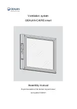
Ventilation system
GEALAN-CAIRE smart
Assembly manual
English translation of the German original manual
Last updated: 02/2021
Page 1: ...Ventilation system GEALAN CAIRE smart Assembly manual English translation of the German original manual Last updated 02 2021...
Page 2: ...n features of warning notices 9 Description 10 Scope of delivery 10 Ventilation profile 12 Fan unit inside and outside 13 Operating modes and LED indicators 14 Power supply unit and PSU holder 15 Acce...
Page 3: ...e external button 31 Cable assignment for the flush mounted button 31 Enabling the external button 31 Commissioning the ventilation system 32 Elimination of faults 34 Dismantling the ventilation syste...
Page 4: ...w Keeping the manual available This manual forms part of the ventilation system Ensure that this manual is available to the user at all times Supply this manual with the ventilation system if you ever...
Page 5: ...in the text they are given a number 1 Numbering starts with the number 1 for each figure Important details are magnified with magnifying glass views Manufacturer s address GEALAN Fenster Systeme GmbH...
Page 6: ...rmation that is subject to copyright This manual may not be copied printed filmed processed reproduced or distributed in any form either in whole or in part without the prior written permission of GEA...
Page 7: ...PA 2 encrypted WLAN network Personnel qualifications This assembly manual is intended for specialists from specialist companies who are trained in the assembly and installation of ventilation systems...
Page 8: ...not place any objects on the ventilation system Only use the ventilation system if it is in a technically perfect condition Send the ventilation system to your specialist dealer immediately if you no...
Page 9: ...g notices DANGER Notes with the word DANGER warn of a dangerous situation that will lead to death or serious injury WARNING Notes with the word WARNING warn of a dangerous situation that may potential...
Page 10: ...Description 10 Description Scope of delivery No Name 1 Screws for assembling the fan unit 4 25 mm 2 Power supply unit 3 Fan unit...
Page 11: ...scope of delivery also includes the following Assembly and operating manual Button for control sticker Template for the sticker Set of screws for the power supply unit Set of screws for fans Two filt...
Page 12: ...Description 12 Ventilation profile No Name 1 Installation opening and mounting hole for the power supply unit 2 Installation opening for the fan unit 3 Openings for supply air and exhaust air...
Page 13: ...air and exhaust air with ventilation flaps outside 3 Tabs 4 Filter flaps 5 Button for operating the ventilation system 6 Control unit with LEDs 7 Cover of the openings for supply air and exhaust air...
Page 14: ...reen Green Green Level 5 Green Green Green Green Green Automatic mode Green Frost protection or moisture protection Blue Blue Blue Blue Blue Blue Night cooling Turquoise Turquoise Turquoise Turquoise...
Page 15: ...Description 15 Power supply unit and PSU holder No Name 1 Insertion side 2 Stop 3 Locating hole 4 Mains cable 24 V 5 Screws 2 3 5 16 mm 6 Mains cable 230 V...
Page 16: ...0 70 230 V connection cable item no 5426 99 Sealing set item no 5694 99 Optional accessories Connection cable for external button item no 5447 99 Insect screen item no 5444 Fine dust F7 replacement fi...
Page 17: ...ontal installation can only be carried out above the window The ventilation system has a position sensor The position sensor detects when the ventilation system is not in the correct position in the v...
Page 18: ...ght 500 g Output 60 W Input voltage 100 230 V AC Output voltage 24 V DC Protection class IP67 Name plate The name plate is located on the front of the ventilation system You will find the following in...
Page 19: ...ng and storing the ventilation system Transport the ventilation system on a pallet in such a way that it is dry and protected from frost Ensure that the pallets are not stacked on top of one another S...
Page 20: ...lation system from the packaging Keep the original packaging so you can potentially return the ventilation system to Customer Service Check the scope of delivery to ensure that it is correct and compl...
Page 21: ...ening in the ventilation profile are marked according to GEALAN specifications Ventilation flaps on the outside of the ventilation profile are already assembled Screws for fastening the ventilation sy...
Page 22: ...stall the ventilation system Align the power supply unit 3 so that it is centred in the PSU holder 2 Connect the power supply unit 3 and the PSU holder 2 with the supplied 3 5 16 mm screws 5 Route the...
Page 23: ...Assembling the ventilation system 23 Stick the seals 1 around the openings for supply air and exhaust air as shown...
Page 24: ...Assembling the ventilation system 24 Pull the existing cover strip 1 from the ventilation profile 2 Put the cover strip 1 to one side...
Page 25: ...nating current exclusively carried out by a qualified electrician Ensure that the power supply unit is dead before carrying out any work on the components Do not connect the power supply unit to the p...
Page 26: ...Assembling the ventilation system 26 Connect the 24 V mains plug of the power supply unit to the plug of the fan unit 1 Connect optional switching elements on the opposite side not included...
Page 27: ...2 along with the PSU holder into the installation opening 1 Push the power supply unit 2 along with the PSU holder and the mains cable 3 first in the direction of the arrow as far as it will go into...
Page 28: ...wer connection must point upwards Ensure that the fan unit s openings for the supply and exhaust air are located in the openings 4 of the ventilation profile Attach the damping rings 6 to the ventilat...
Page 29: ...29 Inserting the filters Proceed as follows to install the filters included in the package Open the two filter flaps 1 in the direction of the arrow Insert the filters 2 as shown Close the filter flap...
Page 30: ...ape self adhesive over the fan unit button as shown Proceed as follows to do this First remove the backing film from one side and stick the double sided hook and loop fastener tape in the position sho...
Page 31: ...l button The following accessories are required to connect the external button Connection cable for external button available from GEALAN item no 5447 99 Floating flush mounted pushbutton not availabl...
Page 32: ...n the following sequence Standby mode Power level 1 Power level 2 Power level 3 Power level 4 Power level 5 The LEDs in the case of horizontal installation starting from the left in the case of vertic...
Page 33: ...ide the cover to the closed position The fan unit s fans switch off The middle four LEDs light up red When the cover is opened again the fan unit starts in the last active operating mode Additional an...
Page 34: ...y The first LED from the left and the first LED from the right light up red The fan unit is not correctly positioned in the ventilation profile Correct the fan unit s position in the ventilation profi...
Page 35: ...stem 35 Dismantling the ventilation system Proceed as follows to dismantle the ventilation system Disconnect the ventilation system from the mains Dismantle it in reverse order to assembly see page 21...
Page 36: ...of the ventilation system through an approved specialist company or send it to your specialist dealer for disposal The ventilation system is mainly made of PA66 103HSL all injection moulded parts It a...
Page 37: ...Warranty 37 Warranty The warranty complies with the statutory provisions...