!
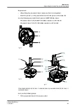
Pneumatic block (8.2): First tighten screw (57.1), then screw (57.2):
tightening torque 1.5 Nm (1.0 lbft).
2.
For fitting the other mounting parts (interface module, adapter module,
solenoid valves, control plate, logic element NOT), see the preceding pages.
®
Done
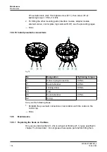
10.4.10 Install pneumatic connections
Fig.78
No.
Designation
Tightening torques
6
Screw-in plug connection
2.0 Nm
21
Sound absorber
2.0 Nm
22
Locking screw
0.5 Nm
23
Plug
26
Sound absorber
2.0 Nm
42
O-ring
Carry out the following steps:
1.
Establish the pneumatic connections in accordance with the codes on the
control top.
®
Done
10.5
Maintenance
10.5.1 Replacing the Seals on the Base
Only use sound absorber (21, 26) or exhaust air throttle (21.1) types specified in
chapter “Technical data” . Do not grease these spare parts before fitting them.
Maintenance
Maintenance
430BAL010697EN_2
102
15.04.2020
Summary of Contents for T.VIS M-15
Page 6: ...430BAL010697EN_2 6 15 04 2020...
Page 53: ...Fig 27 Assembly and installation Electrical connections 430BAL010697EN_2 15 04 2020 53...
Page 55: ...Fig 28 Assembly and installation Electrical connections 430BAL010697EN_2 15 04 2020 55...
Page 119: ...Appendix 430BAL010697EN_2 15 04 2020 119...
Page 120: ......


