


22
D
GB
F
E
I
Ru
96260-08.2015-DGbFEIRu
Οnderung
2
0
Datum
Name
Datum
Bearb.
Gepr.
Norm
1
20.02.2009
bauknecht
04.03.2015
Urspr.
2
Ers. f.
3
Ers. d.
4
D/S MP10
5
6
7
BOCK COMPRESSORS
8
=
+
9
Bl.
6HG76e
Bl.
4
3
X SS
Anschlußkasten Verdichter
BT1
BP1
P-Öl
INT69
QA1
L1
L2
L3
N
PE
FC1.1
I>
I>
I>
1
2
QA2
1
3
4
2
5
6
3
U1
V1
W1
EC1
M
3
˜
1
2
QA4
Y
PE
3
4
5
6
W2
U2
V2
FC1.2
I>
I>
I>
1
2
QA3
4
3
4
5
5
6
6
7
FC1.1
FC1.2
8
FC2
4A
SF1
9
10
11
QA2
12
T2
13
N
14
L
15
M
16
S
BP2
P>
17
QA2
QA2
4.7
6HG76e.7
18
QA4
19
BP3
P
KF4
QA4
QA3
1.8
2.8
4.8
5HG76e.8
5HGZ76e.7
6HG76e.7
20
KF4
QA3
QA4
4.8
6HG76e.8
21
22
KF4
23
24
QA2
25
EB1
26
L1.1
L2.1
L3.1
L1.2
N
PE
OG OG
11
12
14
L
N
B1 B2
BT3
BT2
BT2 BT2
BT2
PE
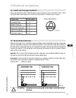
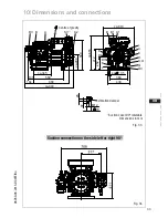
5.5 Circuit diagram for star-delta start 230 V
∆
/ 400 V Y
Fig. 24
BP1
Oil differential pressure monitor
BP2
High pressure safety monitor
BT2.X
Thermal protection thermostat
BP3
Safety chain (high/low pressure monitoring)
BT3
Release switch (thermostat)
EB1
Oil sump heater
EC1
Compressor motor
FC1.1
Motor protection switch (mains contactor)
FC1.2
Motor protection switch (
Δ
-contactor)
Compressor terminal box