


D
GB
F
E
I
Ru
13
96260-08.2015-DGbFEIRu
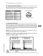
Rigid
fixed point
Fig. 18
As short as
possible
4.6 Laying suction and pressure lines
A rule of thumb:
Always lay the first pipe section starting from the shut-off valve
downwards
and parallel to the drive shaft.
ATTENTION Improperly installed pipes can cause cracks and tears, the result
being a loss of refrigerant.
INFO
Proper layout of the suction and discharge lines directly after
the compressor is integral to the system’s smooth running and
vibration behaviour.
4
|
Compressor assembly
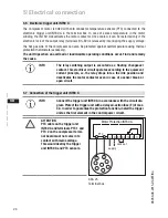
Important:
- Start unloader may only be employed during the starting phase.
- Check the solenoid valve and the non-return valve regulary for tightness.
- In addition, we recommend to use a heat protection thermostat on the discharge side of the com-
pressor. This protects the compressor against thermal overloading. Connect the heat protection
thermostat in series on the safety chain of the control circuit, to switch off the compressor if
necessary.
- Follow these instructions to avoid thermal overloading.
Fig. 17
Solenoid valve dead
Non-return valve open