background image

Summary of Contents for Zoneline 8500 series

Page 1: ...t Back Cover Warranty 27 Cool Only Heat Cool and Heat Pump Hodels 8500 Series Espaflo For a Spanish version of this manual visit our Website at GEAppliances com Para consultar una version en espahol deeste manual de instrucciones site nuestrositio de intemet GEAppliances com Frangaise For a French version of this manual visit our Website at GEAppliances com Pour une version franqaise de ce manuel ...

Page 2: ... or connector end Product must be operated with the electrical plug supplied with the product Do not replace the electrical plug supplied with the product If the receptacle does not match the plug the receptacle must be changed out by a qualified electrician Unplug or disconnect the Zoneline at the fuse box or circuit breaker before making any repairs NOTE We strongly recommend that any servicing ...

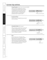
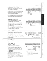
Page 3: ...crew NOTE The owner is responsiblefor setting the appropriate dip switches and connecting terminals TL3 C Temp Limit 3 Cool TL2 C Temp Limit 2 Cool TL C Temp Limit i Cool TL H Temp Limit 1 Heat _TL2 H Temp Limit 2 Heat _TL3 H Temp Limit 3 Heat ALL 12R All Electric Heat Heat pump models only FREEZ S Freeze Sentinel CONST FAN Constant ON Fan DOWN _J I J I j_ N Functi n Reservedf rfutureuse _ DUCT Bl...

Page 4: ...N Constant ONFan Occupancy Sensor Field Supplied When this switch is enabled UP it allows the unit to utilize an infrared motion sensor and a door switch for occupancy detection Thisfeature combined with field devices automatically cycles the unit between normal operation and a preset energy management operation I OCCUPIED OccupancySensor Duct The duct select function allows the indoor fan to be o...

Page 5: ...ches are used to control the heating limits TL3 C Temp Limit S Cool TL2 C Temp Limit 2 Cool TL C Temp Limit Z Cool I L H Temp Limit Heot _ L2 H Temp Limit 2 Heot _TL3 H Temp Limit 3 Heot Temperature limiting during COOL mode oil temperatures shown in F Minimum Maximum 60 85 64 85 66 85 68 85 70 85 72 85 74 85 76 85 UP DOWN NONE 2 3 1 2 3 1 2 3 2 1 3 2 3 1 2 3 NONE 1 3 2 3 1 2 Not opplicoble to Coo...

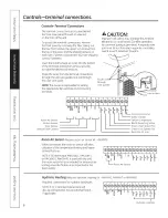
Page 6: ...e wire guide NOTE The owner is responsible for setting the appropriate dip switches and connecting terminals through wire guides connections Room Air Sensor Motion Sensor Door Sensor Central Desk Control e _l _ le_ I _o Io ___ _ o X zo zo _ LL z o Common Ground White Heater Yellow Compressor Black Reversing Valve Green High SpeedFan Green Low SpeedFan Red 24VAConly Room Air Sensor Requiresroom air...

Page 7: ... Desk Control When connected the unit lock out is released and it can be turned ON or OFFwith a switch located at the Central Desk Control A separate wire pair must be run from each separate controlling switch to each individual Zoneline A 24VAC circuit powers the CDCsystem No external power is required e_le_ le_ I _ I_ o _ d _ _ o _ Remote Thermostat The unit will be controlled by o remote thermo...

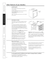
Page 8: ...ce Open O Vent control push lever down and pull forward or back to operate Energy Tip Keepthe vent control in the CLOSE position The room air will be filtered and circulated NOTE Ventilation openings are not intended to be the source of make up air for building ventilation systems due to the additional heating and cooling loads generated About Heat Pumps onsome models Heat pumps can reduce operati...

Page 9: ...cessary Air Filters To maintain optimum performance change the filter at least every 50 days The most important thing you can do to maintain the Zoneline is to change the filter at least every 30 days Dirty filters reduce cooling heating and air flow Changing the filter will Decrease cost of operation saveenergy prevent clogged heat exchanger coils and reduce the risk of premature component failur...

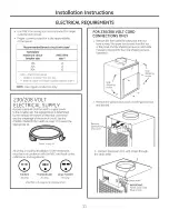
Page 10: ...NING RISK OF ELECTRIC SHOCK All electrical connections and wiring MUST be installed by a qualified electrician Follow the National Electrical Code NEC and or local codes and ordinances o o For personal safety this Zoneline unit and case must be properly grounded Protective devices fuses or circuit breakers acceptable for Zoneline installations are specified on the nameplate of each unit Do not use...

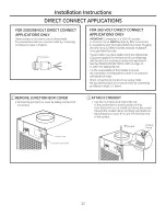
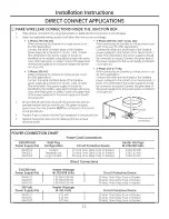
Page 11: ... the amperage of the branch circuit Seethe POWER CONNECTION CHART on page 1 3to select the appropriate kit Power supply kit All wiring including installation of the receptacle must be in accordance with the NECand local codes ordinances and regulations Tandem Perpendicular Large Tandem 15 Amp 20 Amp 30 Amp 230 208 volt receptacle configuration FOR 230 208 VOLT CORD CONNECTIONS ONLY 1 Removethe fro...

Page 12: ...amperage and the electrical resistance heater wattage desired Seethe POWER CONNECTION CHART on page 13 to select the appropriate kit It is the responsibility of the installer to ensure the connection of components is done in accordance with electrical codes Direct connection to branch circuit wiring inside the provided junction box must be made by connecting as follows in steps 1 3 below m l _ REM...

Page 13: ... supply kit to the power supply and branch circuit ground 3 Phase 253 277 VAC When connecting the Zoneline to a three phasecircuit for 265V applications Connect the white and black leads of the Zoneline power supply kit to the branch circuit Neutral and L leads Thewhite lead of the power supply kit should be connected to neutral Connect the green lead of the power supply kit to the power supply an...

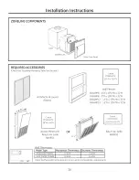
Page 14: ...2 H RAVWP8 8 D x 19s J W x 32 H RAVWP12 12 D x 19 W x 32 H RAVWP15 15 D x 19 W x 32 H Cutout Dimensions 28 W x 48 H Access Panel with OR Return Air Grille 22 RAVRG1 t Cutout Dimensions 20sA W x 20_ H Return Air Grille RAVRG2 Wall Thermostat Model Type Mechanical Thermostat Electronic Thermostat Heat Cool Models 4 wire g wire Heat Pump Models 6 wire 6 wire Check the thermostat instructions for corr...

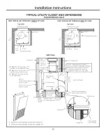
Page 15: ...m S for side install Wall plenum divider Option 1 Access panel wit_ _ return air grille Option 2 Return air grille 8 min Platform 23 x 23 square for drain Min load capacity 17S Ibs access B A Minimum recommended access door width 30 B Minimum recommended access door height 50 11_ 5 min 2C dt _ Door access panel Unit front 5 min Outside wall 14 min Required only if optional Hydronic Heating Kit RAV...

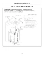
Page 16: ...y Outside wall D 230 208 VAC wall receptacle F or G conduit for direct connection Reference Dimensions A Thermostat cable 9 long B Power cord 60 long C Case width and depth 23 D Case height 31 E Condensate drains 3 4 connector Primary Drain Centerline of cutout is approximately 51A from left case wall and 8 from back case wall Secondary Drain Centerline of cutout is approximately 61 2 from left ca...

Page 17: ...oose the option that best suits your installation requirements Follow the Installation Instructions provided with the return air grille accessory for installation details NOTE Use only one filter in the installation The filter may be installed on the unit or in the access panel door Outside wall RAVRGI Access panel with return air grille Option 1 Unit mounted filter with a field supplied return ai...

Page 18: ...imum of 8 NOTE The platform must have a loud bearing capacity of 175 Ibs minimum Left side of platform Back of platform 23 5 min for f drain access NOTE Specific cutout size for drain connections needs to be determined by the installer for the given installation situation Cutout for drain connection s see NOTEbelow 18 2 Make drain hole cutout s Primary Drain Centerline of drain is approximately 5 ...

Page 19: ...speed setting The collar on top of the case accepts standard 10 duct Pullall duct tight Extra duct slack can greatly increase static pressure NOTICE Fie duct con collapse and cause airflow restrictions Do not use flex duct for 90 bends or unsupported runs of 5 ft or more Airflow CFM 230Voltsand 265 Volts ESP in water 8 o o 0 1 0 2 8 o s 0 4 8 o o 04 z 0 2 0 3 0 4 Indoor FanCFM DUCT SELECT SWITCH U...

Page 20: ...iiiiiiii_i_ External drain OR _ _ Internal drainls _ INSTALL AND GROUND THE UNIT TO THE CASE UNIT INSTALLED THROUGH FRONT OF CASE 1 Slidethe back of the unit into the case Pushthe unit all of the way into the case until it stops NOTE Either of the case sides may be removed to enable the unit to be slid into the case 2 Ground the unit to the case by installing the front case to unit hex bolt and di...

Page 21: ...0 ft for AWG 20 40 ft for AWG 24 AWG American Wire Gauge 2 Hake power connections to the unit NOTE See the ELECTRICALREQUIREMENTSand DIRECT CONNECTAPPLICATIONS sections as appropriate of this manual for proper connections 3 Replace the case front panel by replacing the four front screws and the two top screws 7 CONNECT THE TOP DUCT Install the duct onto the air discharge outlet Inside wall Air dis...

Page 22: ... of the switch in SERVICING WARNING Risk of Electric Shock can cause injury or death Before servicing switch power off at the service panel and lock the area to prevent power from being switched on accidentally When the area cannot be locked securely fasten u prominent warning device such as a tag to the service panel NOTE We strongly recommend that any servicing be performed by a qualified indivi...

Page 23: ...is not restricted Thiscan cause the unit to cycle off due to the compressor overload Outdoor grille must have a minimum of 65 free area Non GEgrilles may be too restrictive for proper performance Consult your salesperson for assistance The air filter is dirty Change the filter at least every 30 days Seethe Cure and Cleaning Air Filterssection The room may have been hot or cold When the Zoneline is...

Page 24: ...is set at fan cycle up Thiswill cause the fan to cycle on and off with the compressor You may also hear a fan noise stop and start _ x e 5 You may notice a few minutes delay in starting if you try to restart the Zoneline too soon after turning it off or if you adjust the thermostat right after the compressor has shut off This isdue to a built in restart protector for the compressor that causes a 3...

Page 25: ...Notes GEAppliances c0m oo Q tn m c N 0 09 0 3 d m o c D tn m c N 0 09 N Q Q Q_ N d Q c D 4 m 0 c CY d tn _ 7 0 0 c D 4 3 09 N 0 tn r 3 d O0 C 3 0 25 ...

Page 26: ...m co Notes E 0 i u L co t o u co c O i u L co ci r i o L c_ O O3 C i c o D i u o c o o u co i F r i O O ci co D i O L F O Q_ U3 L E co c O u 26 ...

Page 27: ...or installer You are responsible for providing adequate electrical connecting facilities In commercial locations labor necessary to move the unit to a location where it is accessible for service by an individual technician Failure or damage resulting from corrosion due to installation in an environment containing corrosive chemicals Replacement of fuses or resetting of circuit breakers Filters Fai...

Page 28: ...our Website today Forthe hearing impaired please call 800 TDD GEAC 800 833 4322 Parts and Accessories G EAppliances corn Individuals qualified to service their own appliances can have parts or accessoriessent directly to their homes VISA IViasterCardand Discovercards are accepted Order on line today 24 hours every day or by phone at 800 626 2002 during normal business hours Instructions contained ...

Reviews: