


GE Multilin
T60 Transformer Protection System
2-19
2 PRODUCT DESCRIPTION
2.2 SPECIFICATIONS
2
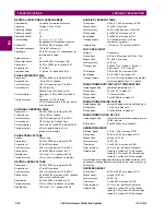
2.2.8 COMMUNICATIONS
RS232
Front port:
19.2 kbps, Modbus
®
RTU
RS485
1 or 2 rear ports:
Up to 115 kbps, Modbus
®
RTU, DNP 3
Typical distance:
1200 m
Isolation:
2 kV, isolated together at 36 Vpk
ETHERNET (FIBER)
The UR-2S and UR-2T only support 100 Mb multimode
ETHERNET (10/100 MB TWISTED PAIR)
Modes:
10 MB, 10/100 MB (auto-detect)
Connector:
RJ45
SNTP clock synchronization error: <10 ms (typical)
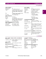
ETHERNET SWITCH FIBER OPTIC PORTS
Maximum fiber segment length calculation:
The maximum fiber segment length between two adjacent
switches or between a switch and a device is calculated as fol-
lows. First, calculate the optical power budget (OPB) of each
device using the manufacturer’s data sheets.
where OPB = optical power budget,
P
T
= transmitter output power,
and
P
R
= receiver sensitivity.
The worst case optical power budget (OPB
WORST
) is then calcu-
lated by taking the lower of the two calculated power budgets, sub-
tracting 1 dB for LED aging, and then subtracting the total insertion
loss. The total insertion loss is calculated by multiplying the num-
ber of connectors in each single fiber path by 0.5 dB. For example,
with a single fiber cable between the two devices, there will be a
minimum of two connections in either transmit or receive fiber
paths for a total insertion loss of 1db for either direction:
The worst-case optical power budget between two type 2T or 2S
modules using a single fiber cable is:
To calculate the maximum fiber length, divide the worst-case opti-
cal power budget by the cable attenuation per unit distance speci-
fied in the manufacturer data sheets. For example, typical
attenuation for 62.5/125
μ
m glass fiber optic cable is approxi-
mately 2.8 dB per km. In our example, this would result in the fol-
lowing maximum fiber length:
The customer must use the attenuation specified within the manu-
facturer data sheets for accurate calculation of the maximum fiber
length.
ETHERNET SWITCH 10/100BASE-T PORTS
Connector type:
RJ45
MAXIMUM 10 MBPS ETHERNET SEGMENT LENGTHS
Unshielded twisted pair: 100 m (328 ft.)
Shielded twisted pair: 150 m (492 ft.)
MAXIMUM STANDARD FAST ETHERNET SEGMENT LENGTHS
10Base-T (CAT 3, 4, 5 UTP): 100 m (328 ft.)
100Base-TX (CAT 5 UTP):100 m (328 ft.)
Shielded twisted pair: 150 m (492 ft.)
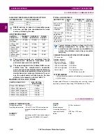
PARAMETER
FIBER TYPE
10MB MULTI-
MODE
100MB MULTI-
MODE
100MB SINGLE-
MODE
Wavelength
820 nm
1310 nm
1310 nm
Connector
ST
ST
SC
Transmit power
–20 dBm
–20 dBm
–15 dBm
Receiver sensitivity
–30 dBm
–30 dBm
–30 dBm
Power budget
10 dB
10 dB
15 dB
Maximum input
power
–7.6 dBm
–14 dBm
–7 dBm
Typical distance
1.65 km
2 km
15 km
Duplex
full/half
full/half
full/half
Redundancy
yes
yes
yes
OPB
P
T MIN
(
)
P
R MIN
(
)
–
=
Total insertion loss
number of connectors 0.5 dB
×
=
2 0.5 dB
×
=
1.0 dB
=
OPB
WORST
OPB 1 dB (LED aging)
–
total insertion loss
–
=
10
dB
1
dB
–
1
dB
–
8
dB
=
Maximum fiber length
OPB
WORST
(in dB)
cable loss (in dB/km)
-------------------------------------------------------
=
8 dB
2.8 dB/km
---------------------------
=
2.8
km
=
Summary of Contents for UR T60
Page 10: ...x T60 Transformer Protection System GE Multilin TABLE OF CONTENTS ...
Page 14: ...xiv T60 Transformer Protection System GE Multilin 0 1 BATTERY DISPOSAL 0 BATTERY DISPOSAL 0 ...
Page 34: ...1 20 T60 Transformer Protection System GE Multilin 1 5 USING THE RELAY 1 GETTING STARTED 1 ...
Page 436: ...5 298 T60 Transformer Protection System GE Multilin 5 10 TESTING 5 SETTINGS 5 ...
Page 678: ...C 30 T60 Transformer Protection System GE Multilin C 7 LOGICAL NODES APPENDIX C C ...
Page 688: ...D 10 T60 Transformer Protection System GE Multilin D 1 IEC 60870 5 104 PROTOCOL APPENDIX D D ...
Page 700: ...E 12 T60 Transformer Protection System GE Multilin E 2 DNP POINT LISTS APPENDIX E E ...


