


GE Multilin
T60 Transformer Protection System
6-27
6 ACTUAL VALUES
6.4 RECORDS
6
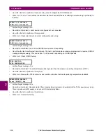
6.4.5 PHASOR MEASUREMENT UNIT RECORDS
PATH: ACTUAL VALUES
RECORDS
PMU RECORDS
The number of triggers applicable to the phasor measurement unit recorder is indicated by the
NUMBER OF TRIGGERS
value.
The status of the phasor measurement unit recorder is indicated as follows:
PATH: ACTUAL VALUES
RECORDS
PMU RECORDS
PMU 1 RECORDING
6.4.6 BREAKER MAINTENANCE
PATH: ACTUAL VALUES
RECORDS
MAINTENANCE
BREAKER 1(4)
There is an identical menu for each of the breakers. The
BKR 1 ARCING AMP
values are in units of kA
2
-cycles. Refer to the
COMMANDS
CLEAR RECORDS
menu for clearing breaker arcing current records. The
BREAKER OPERATING TIME
is
defined as the slowest operating time of breaker poles that were initiated to open.
PMU
RECORDS
NUMBER OF TRIGGERS:
0
Range: 0 to 65535 in steps of 1
MESSAGE
PMU 1
RECORDING
See below.
PMU 1
RECORDING
PMU 1 FORCE TRIGGER:
Yes
Range: No, Yes
MESSAGE
PUM 1 AVAILABLE
RECORDS: 0
Range: 0 to 65535 in steps of 1
MESSAGE
PUM 1 SECONDS
PER RECORD: 0.0
Range: 0 to 6553.5 in steps of 0.1
MESSAGE
PUM 1 LAST CLEARED:
2005/07/14 15:40:16
Range: date and time in format shown
BREAKER 1
BKR 1 ARCING AMP
φ
A:
0.00 kA2-cyc
MESSAGE
BKR 1 ARCING AMP
φ
B:
0.00 kA2-cyc
MESSAGE
BKR 1 ARCING AMP
φ
C:
0.00 kA2-cyc
MESSAGE
BKR 1 OPERATING TIME
φ
A: 0
ms
MESSAGE
BKR 1 OPERATING TIME
φ
B: 0
ms
MESSAGE
BKR 1 OPERATING TIME
φ
C: 0
ms
MESSAGE
BKR 1 OPERATING
TIME:
0 ms
Summary of Contents for UR T60
Page 10: ...x T60 Transformer Protection System GE Multilin TABLE OF CONTENTS ...
Page 14: ...xiv T60 Transformer Protection System GE Multilin 0 1 BATTERY DISPOSAL 0 BATTERY DISPOSAL 0 ...
Page 34: ...1 20 T60 Transformer Protection System GE Multilin 1 5 USING THE RELAY 1 GETTING STARTED 1 ...
Page 436: ...5 298 T60 Transformer Protection System GE Multilin 5 10 TESTING 5 SETTINGS 5 ...
Page 678: ...C 30 T60 Transformer Protection System GE Multilin C 7 LOGICAL NODES APPENDIX C C ...
Page 688: ...D 10 T60 Transformer Protection System GE Multilin D 1 IEC 60870 5 104 PROTOCOL APPENDIX D D ...
Page 700: ...E 12 T60 Transformer Protection System GE Multilin E 2 DNP POINT LISTS APPENDIX E E ...


