


GE Multilin
T60 Transformer Protection System
6-5
6 ACTUAL VALUES
6.2 STATUS
6
6.2.4 TELEPROTECTION INPUTS
PATH: ACTUAL VALUES
STATUS
TELEPROTECTION INPUTS
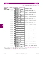
The present state of teleprotection inputs from communication channels 1 and 2 are shown here. The state displayed will
be that of corresponding remote output unless the channel is declared failed.
6.2.5 CONTACT OUTPUTS
PATH: ACTUAL VALUES
STATUS
CONTACT OUTPUTS
The present state of the contact outputs is shown here. The first line of a message display indicates the ID of the contact
output. For example, ‘Cont Op 1’ refers to the contact output in terms of the default name-array index. The second line of
the display indicates the logic state of the contact output.
For form-A contact outputs, the state of the voltage and current detectors is displayed as Off, VOff, IOff,
On, IOn, and VOn. For form-C contact outputs, the state is displayed as Off or On.
TELEPROTECTION
INPUTS
TELEPROTECTION
INPUT 1-1: Off
Range: Off, On
MESSAGE
TELEPROTECTION
INPUT 1-2: Off
Range: Off, On
↓
MESSAGE
TELEPROTECTION
INPUT 1-16: Off
Range: Off, On
MESSAGE
TELEPROTECTION
INPUT 2-1: Off
Range: Off, On
MESSAGE
TELEPROTECTION
INPUT 2-2: Off
Range: Off, On
↓
MESSAGE
TELEPROTECTION
INPUT 2-16: Off
Range: Off, On
CONTACT OUTPUTS
Cont Op 1
Off
Range: On, Off, VOff, VOn, IOn, IOff
MESSAGE
Cont Op 2
Off
Range: On, Off, VOff, VOn, IOn, IOff
↓
MESSAGE
Cont Op xx
Off
Range: On, Off, VOff, VOn, IOn, IOff
NOTE
Summary of Contents for UR T60
Page 10: ...x T60 Transformer Protection System GE Multilin TABLE OF CONTENTS ...
Page 14: ...xiv T60 Transformer Protection System GE Multilin 0 1 BATTERY DISPOSAL 0 BATTERY DISPOSAL 0 ...
Page 34: ...1 20 T60 Transformer Protection System GE Multilin 1 5 USING THE RELAY 1 GETTING STARTED 1 ...
Page 436: ...5 298 T60 Transformer Protection System GE Multilin 5 10 TESTING 5 SETTINGS 5 ...
Page 678: ...C 30 T60 Transformer Protection System GE Multilin C 7 LOGICAL NODES APPENDIX C C ...
Page 688: ...D 10 T60 Transformer Protection System GE Multilin D 1 IEC 60870 5 104 PROTOCOL APPENDIX D D ...
Page 700: ...E 12 T60 Transformer Protection System GE Multilin E 2 DNP POINT LISTS APPENDIX E E ...


