


GE Multilin
T60 Transformer Protection System
5-263
5 SETTINGS
5.7 CONTROL ELEMENTS
5
•
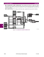
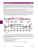
TRANS BLOCK PICKUP DELAY:
This setting defines a transient blocking mechanism embedded in the POTT
scheme for coping with the exposure of a ground directional overcurrent function (if used) to current reversal condi-
tions. The transient blocking mechanism applies to the ground overcurrent path only as the reach settings for the zone
2 distance functions is not expected to be long for two-terminal applications, and the security of the distance functions
is not endangered by the current reversal conditions. Upon receiving the
POTT RX
signal, the transient blocking mech-
anism allows the
RX
signal to be passed and aligned with the
GND DIR O/C FWD
indication only for a period of time
defined as
TRANS BLOCK PICKUP DELAY
. After that the ground directional overcurrent path will be virtually disabled for a
period of time specified as
TRANS BLOCK RESET DELAY
.
The
TRANS BLOCK PICKUP DELAY
should be long enough to give the selected ground directional overcurrent function
time to operate, but not longer than the fastest possible operation time of the protection system that can create current
reversal conditions within the reach of the selected ground directional overcurrent function. This setting should take
into account the
POTT RX PICKUP DELAY
. The
POTT RX
signal is shaped for aligning with the ground directional indica-
tion as follows: the original
RX
signal is delayed by the
POTT RX PICKUP DELAY
, then terminated at
TRANS BLOCK PICKUP
DELAY
after the pickup of the original
POTT TX
signal, and eventually, locked-out for
TRANS BLOCK RESET DELAY
.
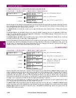
•
TRANS BLOCK RESET DELAY:
This setting defines a transient blocking mechanism embedded in the POTT scheme
for coping with the exposure of a ground directional overcurrent function (if used) to current reversal conditions (see
also the
TRANS BLOCK PICKUP DELAY
). This delay should be selected long enough to cope with transient conditions
including not only current reversals but also spurious negative and zero-sequence currents occurring during breaker
operations. The breaker failure time of the surrounding protection systems within the reach of the ground directional
function used by the POTT scheme may be considered to make sure that the ground directional function is not jeopar-
dized during delayed breaker operations.
•
ECHO DURATION:
This setting defines the guaranteed and exact duration of the echo pulse. The duration does not
depend on the duration and shape of the received
POTT RX
signal. This setting enables the relay to avoid a permanent
lock-up of the transmit/receive loop.
•
ECHO LOCKOUT:
This setting defines the lockout period for the echo logic after sending the echo pulse.
•
LINE END OPEN PICKUP DELAY:
This setting defines the pickup setting for validation of the line end open conditions
as detected by the Line Pickup logic through the
LINE PICKUP LEO PKP
FlexLogic™ operand. The validated line end
open condition is a requirement for the POTT scheme to return a received echo signal (if the echo feature is enabled).
The value of this setting should take into account the principle of operation and settings of the line pickup element.
•
POTT SEAL-IN DELAY:
The output FlexLogic™ operand (
POTT OP
) is produced according to the POTT scheme logic.
A seal-in time delay is applied to this operand for coping with noisy communication channels. This setting specifies a
minimum guaranteed duration of the
POTT OP
pulse.
•
GND DIR O/C FWD:
This setting selectes the FlexLogic™ operand (if any) of a protection element used in addition to
zone 2 for identifying faults on the protected line, and thus, for keying the communication channel and initiating opera-
tion of the scheme. Good directional integrity is the key requirement for an over-reaching forward-looking protection
element used as
GND DIR O/C FWD
. Even though any FlexLogic™ operand could be used as
GND DIR O/C FWD
allowing
the user to combine responses of various protection elements, or to apply extra conditions through FlexLogic™ equa-
tions, this extra signal is primarily meant to be the output operand from either the negative-sequence directional over-
current or neutral directional overcurrent elements. Both of these elements have separate forward and reverse output
operands. The forward indication should be used (
NEG SEQ DIR OC1 FWD
or
NEUTRAL DIR OC1 FWD
). For greater security
and to overcome spurious directional element operation during transients, adding at least 0.5 cycles of pickup delay to
the forward directional element is recommended.
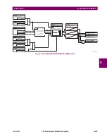
•
POTT RX:
This setting enables the user to select the FlexLogic™ operand that represents the receive signal (
RX
) for
the scheme. Typically an input contact interfacing with a signaling system is used. Other choices include remote inputs
and FlexLogic™ equations. The POTT transmit signal (
TX
) should be appropriately interfaced with the signaling sys-
tem by assigning the output FlexLogic™ operand (
POTT TX
) to an output contact. The remote output mechanism is
another choice.
The output operand from the scheme (
POTT OP
) must be configured to interface with other relay functions, output con-
tacts in particular, in order to make the scheme fully operational. Typically, the output operand should be programmed
to initiate a trip, breaker fail, and autoreclose, and drive a user-programmable LED as per user application.
Summary of Contents for UR T60
Page 10: ...x T60 Transformer Protection System GE Multilin TABLE OF CONTENTS ...
Page 14: ...xiv T60 Transformer Protection System GE Multilin 0 1 BATTERY DISPOSAL 0 BATTERY DISPOSAL 0 ...
Page 34: ...1 20 T60 Transformer Protection System GE Multilin 1 5 USING THE RELAY 1 GETTING STARTED 1 ...
Page 436: ...5 298 T60 Transformer Protection System GE Multilin 5 10 TESTING 5 SETTINGS 5 ...
Page 678: ...C 30 T60 Transformer Protection System GE Multilin C 7 LOGICAL NODES APPENDIX C C ...
Page 688: ...D 10 T60 Transformer Protection System GE Multilin D 1 IEC 60870 5 104 PROTOCOL APPENDIX D D ...
Page 700: ...E 12 T60 Transformer Protection System GE Multilin E 2 DNP POINT LISTS APPENDIX E E ...


