


GE Multilin
T60 Transformer Protection System
5-251
5 SETTINGS
5.7 CONTROL ELEMENTS
5
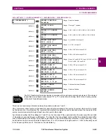
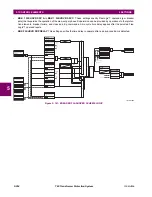
c) BREAKER FLASHOVER
PATH: SETTINGS
CONTROL ELEMENTS
MONITORING ELEMENTS
BREAKER FLASHOVER 1(2)
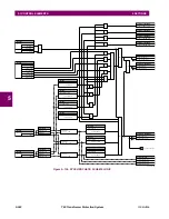
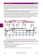
The detection of the breaker flashover is based on the following condition:
1.
Breaker open,
2.
Voltage drop measured from either side of the breaker during the flashover period,
3.
Voltage difference drop, and
4.
Measured flashover current through the breaker.
Furthermore, the scheme is applicable for cases where either one or two sets of three-phase voltages are available across
the breaker.
BREAKER
FLASHOVER 1
BKR 1 FLSHOVR
FUNCTION: Disabled
Range: Disabled, Enabled
MESSAGE
BKR 1 FLSHOVR SIDE 1
SRC: SRC 1
Range: SRC 1, SRC 2, SRC 3, SRC 4, SRC 5, SRC 6
MESSAGE
BKR 1 FLSHOVR SIDE 2
SRC: None
Range: None, SRC 1, SRC 2, SRC 3, SRC 4, SRC 5,
SRC 6
MESSAGE
BKR 1 STATUS CLSD A:
Off
Range: FlexLogic™ operand
MESSAGE
BKR 1 STATUS CLSD B:
Off
Range: FlexLogic™ operand
MESSAGE
BKR 1 STATUS CLSD C:
Off
Range: FlexLogic™ operand
MESSAGE
BKR 1 FLSHOVR V PKP:
0.850 pu
Range: 0.000 to 1.500 pu in steps of 0.001
MESSAGE
BKR 1 FLSHOVR DIFF V
PKP: 1000 V
Range: 0 to 100000 V in steps of 1
MESSAGE
BKR 1 FLSHOVR AMP
PKP: 0.600 pu
Range: 0.000 to 1.500 pu in steps of 0.001
MESSAGE
BKR 1 FLSHOVR PKP
DELAY: 0.100 s
Range: 0.000 to 65.535 s in steps of 0.001
MESSAGE
BKR 1 FLSHOVR SPV A:
Off
Range: FlexLogic™ operand
MESSAGE
BKR 1 FLSHOVR SPV B:
Off
Range: FlexLogic™ operand
MESSAGE
BKR 1 FLSHOVR SPV C:
Off
Range: FlexLogic™ operand
MESSAGE
BKR 1 FLSHOVR BLOCK:
Off
Range: FlexLogic™ operand
MESSAGE
BKR 1 FLSHOVR
TARGET: Self-reset
Range: Self-reset, Latched, Disabled
MESSAGE
BKR 1 FLSHOVR
EVENTS: Disabled
Range: Disabled, Enabled
Summary of Contents for UR T60
Page 10: ...x T60 Transformer Protection System GE Multilin TABLE OF CONTENTS ...
Page 14: ...xiv T60 Transformer Protection System GE Multilin 0 1 BATTERY DISPOSAL 0 BATTERY DISPOSAL 0 ...
Page 34: ...1 20 T60 Transformer Protection System GE Multilin 1 5 USING THE RELAY 1 GETTING STARTED 1 ...
Page 436: ...5 298 T60 Transformer Protection System GE Multilin 5 10 TESTING 5 SETTINGS 5 ...
Page 678: ...C 30 T60 Transformer Protection System GE Multilin C 7 LOGICAL NODES APPENDIX C C ...
Page 688: ...D 10 T60 Transformer Protection System GE Multilin D 1 IEC 60870 5 104 PROTOCOL APPENDIX D D ...
Page 700: ...E 12 T60 Transformer Protection System GE Multilin E 2 DNP POINT LISTS APPENDIX E E ...


