


GE Multilin
T60 Transformer Protection System
5-239
5 SETTINGS
5.7 CONTROL ELEMENTS
5
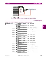
5.7.7 SYNCHROCHECK
PATH: SETTINGS
CONTROL ELEMENTS
SYNCHROCHECK
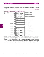
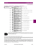
SYNCHROCHECK 1(2)
The T60 Transformer Protection System is provided with an optional synchrocheck element. This element
is specified as a software option (select “10” or “11”) at the time of ordering. Refer to the
Ordering
section
of chapter 2 for additional details.
There are two identical synchrocheck elements available, numbered 1 and 2.
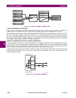
The synchronism check function is intended for supervising the paralleling of two parts of a system which are to be joined
by the closure of a circuit breaker. The synchrocheck elements are typically used at locations where the two parts of the
system are interconnected through at least one other point in the system.
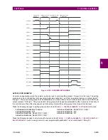
Synchrocheck verifies that the voltages (V1 and V2) on the two sides of the supervised circuit breaker are within set limits
of magnitude, angle and frequency differences. The time that the two voltages remain within the admissible angle differ-
ence is determined by the setting of the phase angle difference
ΔΦ
and the frequency difference
Δ
F (slip frequency). It can
be defined as the time it would take the voltage phasor V1 or V2 to traverse an angle equal to 2
×
ΔΦ
at a frequency equal
to the frequency difference
Δ
F. This time can be calculated by:
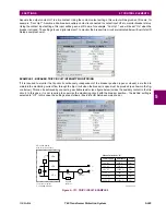
SYNCHROCHECK 1
SYNCHK1 FUNCTION:
Disabled
Range: Disabled, Enabled
MESSAGE
SYNCHK1 BLOCK:
Off
Range: FlexLogic™ operand
MESSAGE
SYNCHK1 V1 SOURCE:
SRC 1
Range: SRC 1, SRC 2, SRC 3, SRC 4, SRC 5, SRC 6
MESSAGE
SYNCHK1 V2 SOURCE:
SRC 2
Range: SRC 1, SRC 2, SRC 3, SRC 4, SRC 5, SRC 6
MESSAGE
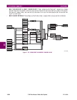
SYNCHK1 MAX VOLT
DIFF: 10000 V
Range: 0 to 400000 V in steps of 1
MESSAGE
SYNCHK1 MAX ANGLE
DIFF: 30°
Range: 0 to 100° in steps of 1
MESSAGE
SYNCHK1 MAX FREQ
DIFF: 1.00 Hz
Range: 0.00 to 2.00 Hz in steps of 0.01
MESSAGE
SYNCHK1 MAX FREQ
HYSTERESIS: 0.06 Hz
Range: 0.00 to 0.10 Hz in steps of 0.01
MESSAGE
SYNCHK1 DEAD SOURCE
SELECT: LV1 and DV2
Range: None, LV1 and DV2, DV1 and LV2, DV1 or DV2,
DV1 Xor DV2, DV1 and DV2
MESSAGE
SYNCHK1 DEAD V1
MAX VOLT: 0.30 pu
Range: 0.00 to 1.25 pu in steps of 0.01
MESSAGE
SYNCHK1 DEAD V2
MAX VOLT: 0.30 pu
Range: 0.00 to 1.25 pu in steps of 0.01
MESSAGE
SYNCHK1 LIVE V1
MIN VOLT: 0.70 pu
Range: 0.00 to 1.25 pu in steps of 0.01
MESSAGE
SYNCHK1 LIVE V2
MIN VOLT: 0.70 pu
Range: 0.00 to 1.25 pu in steps of 0.01
MESSAGE
SYNCHK1 TARGET:
Self-reset
Range: Self-reset, Latched, Disabled
MESSAGE
SYNCHK1 EVENTS:
Disabled
Range: Disabled, Enabled
Summary of Contents for UR T60
Page 10: ...x T60 Transformer Protection System GE Multilin TABLE OF CONTENTS ...
Page 14: ...xiv T60 Transformer Protection System GE Multilin 0 1 BATTERY DISPOSAL 0 BATTERY DISPOSAL 0 ...
Page 34: ...1 20 T60 Transformer Protection System GE Multilin 1 5 USING THE RELAY 1 GETTING STARTED 1 ...
Page 436: ...5 298 T60 Transformer Protection System GE Multilin 5 10 TESTING 5 SETTINGS 5 ...
Page 678: ...C 30 T60 Transformer Protection System GE Multilin C 7 LOGICAL NODES APPENDIX C C ...
Page 688: ...D 10 T60 Transformer Protection System GE Multilin D 1 IEC 60870 5 104 PROTOCOL APPENDIX D D ...
Page 700: ...E 12 T60 Transformer Protection System GE Multilin E 2 DNP POINT LISTS APPENDIX E E ...


