


2-2
T60 Transformer Protection System
GE Multilin
2.1 INTRODUCTION
2 PRODUCT DESCRIPTION
2
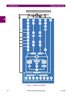
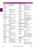
Figure 2–1: SINGLE LINE DIAGRAM
828713AH.CDR
Winding 2
Amps
Amps
50/87
87T
Block
3
3
Calculate
restraint
amps
Calculate
operate amps
Metering
Calculate
2nd and 5th
harmonics
Harmonic
restraint
TYPICAL CONFIGURATION (
the AC signal path is configurable)
59N
24
Winding 1
Amps
Amps
51N-1
50N-1
51N-2
50N-2
Calculate
3I_0
Calculate
3I_0
Amps
50P-2
51P-2
50P-1
21G
51P-1
21P
50G-1
51G-1
87RGF-1
50G-2
51G-2
87RGF-2
27X
81U
81O
Transducer Input
TM
FlexElement
68
78
67P
67N
3V_0
Amps
50BF-2
50BF-1
49
59P
27P
59X
T60 T
ransformer Protection System
49
49
Summary of Contents for UR T60
Page 10: ...x T60 Transformer Protection System GE Multilin TABLE OF CONTENTS ...
Page 14: ...xiv T60 Transformer Protection System GE Multilin 0 1 BATTERY DISPOSAL 0 BATTERY DISPOSAL 0 ...
Page 34: ...1 20 T60 Transformer Protection System GE Multilin 1 5 USING THE RELAY 1 GETTING STARTED 1 ...
Page 436: ...5 298 T60 Transformer Protection System GE Multilin 5 10 TESTING 5 SETTINGS 5 ...
Page 678: ...C 30 T60 Transformer Protection System GE Multilin C 7 LOGICAL NODES APPENDIX C C ...
Page 688: ...D 10 T60 Transformer Protection System GE Multilin D 1 IEC 60870 5 104 PROTOCOL APPENDIX D D ...
Page 700: ...E 12 T60 Transformer Protection System GE Multilin E 2 DNP POINT LISTS APPENDIX E E ...


