


GE Multilin
T60 Transformer Protection System
5-203
5 SETTINGS
5.6 GROUPED ELEMENTS
5
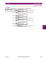
c) GROUND INSTANTANEOUS OVERCURRENT
(ANSI 50G)
PATH: SETTINGS
GROUPED ELEMENTS
SETTING GROUP 1(6)
GROUND CURRENT
GROUND IOC1(12)
The ground instantaneous overcurrent element may be used as an instantaneous element with no intentional delay or as a
definite time element. The ground current input is the quantity measured by the ground input CT and is the fundamental
phasor magnitude.
These elements measure the current that is connected to the ground channel of a CT/VT module. The conversion
range of a standard channel is from 0.02 to 46 times the CT rating.
This channel may be equipped with a standard or sensitive input. The conversion range of a sensitive channel is
from 0.002 to 4.6 times the CT rating.
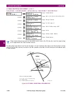
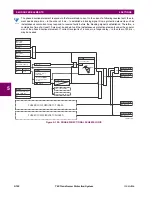
Figure 5–106: GROUND IOC1 SCHEME LOGIC
GROUND IOC1
GROUND IOC1
FUNCTION: Disabled
Range: Disabled, Enabled
MESSAGE
GROUND IOC1 SIGNAL
SOURCE: SRC 1
Range: SRC 1, SRC 2, SRC 3, SRC 4, SRC 5, SRC 6
MESSAGE
GROUND IOC1
PICKUP: 1.000
pu
Range: 0.000 to 30.000 pu in steps of 0.001
MESSAGE
GROUND IOC1 PICKUP
DELAY: 0.00
s
Range: 0.00 to 600.00 s in steps of 0.01
MESSAGE
GROUND IOC1 RESET
DELAY: 0.00
s
Range: 0.00 to 600.00 s in steps of 0.01
MESSAGE
GROUND IOC1 BLOCK:
Off
Range: FlexLogic™ operand
MESSAGE
GROUND IOC1
TARGET: Self-reset
Range: Self-reset, Latched
,
Disabled
MESSAGE
GROUND IOC1
EVENTS: Disabled
Range: Disabled, Enabled
NOTE
NOTE
S
ETT
I
NG
GROUND IOC1
FUNCTION:
Disabled = 0
Enabled = 1
S
ETT
I
NG
GROUND IOC1
SOURCE:
IG
GROUND IOC1
BLOCK:
Off = 0
FLEXLOG
I
C OPE
R
AND
S
GROUND IOIC DPO
GROUND IOC1 OP
S
ETT
I
NG
S
ETT
I
NG
IG
≥
PICKUP
GROUND IOC1
PICKUP:
RUN
GROUND IOC1 PICKUP
DELAY:
S
ETT
I
NG
S
GROUND IOC1 RESET
DELAY:
t
PKP
t
RST
827037A4.VSD
AND
GROUND IOC1 PKP
Summary of Contents for UR T60
Page 10: ...x T60 Transformer Protection System GE Multilin TABLE OF CONTENTS ...
Page 14: ...xiv T60 Transformer Protection System GE Multilin 0 1 BATTERY DISPOSAL 0 BATTERY DISPOSAL 0 ...
Page 34: ...1 20 T60 Transformer Protection System GE Multilin 1 5 USING THE RELAY 1 GETTING STARTED 1 ...
Page 436: ...5 298 T60 Transformer Protection System GE Multilin 5 10 TESTING 5 SETTINGS 5 ...
Page 678: ...C 30 T60 Transformer Protection System GE Multilin C 7 LOGICAL NODES APPENDIX C C ...
Page 688: ...D 10 T60 Transformer Protection System GE Multilin D 1 IEC 60870 5 104 PROTOCOL APPENDIX D D ...
Page 700: ...E 12 T60 Transformer Protection System GE Multilin E 2 DNP POINT LISTS APPENDIX E E ...


