


5-112
T60 Transformer Protection System
GE Multilin
5.4 SYSTEM SETUP
5 SETTINGS
5
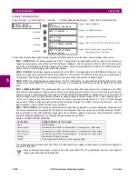
h) VOLTAGE TRIGGERING
PATH: SETTINGS
SYSTEM SETUP
PHASOR MEASUREMENT...
PMU 1 TRIGGERING
PMU 1 VOLTAGE TRIGGER
This element responds to abnormal voltage. Separate thresholds are provided for low and high voltage. In terms of signal-
ing its operation, the element does not differentiate between the undervoltage and overvoltage events. The trigger
responds to the phase voltage signal of the phasor measurement unit (PMU) source. All voltage channels (A, B, and C or
AB, BC, and CA) are processed independently and could trigger the recorder. A minimum voltage supervision of 0.1 pu is
implemented to prevent pickup on a de-energized circuit, similarly to the undervoltage protection element.
•
PMU 1 VOLT TRIGGER LOW-VOLT
: This setting specifies the low threshold for the abnormal voltage trigger, in per-
unit of the PMU source. 1 pu is a nominal voltage value defined as the nominal secondary voltage times VT ratio. The
comparator applies a 3% hysteresis.
•
PMU 1 VOLT TRIGGER HIGH-VOLT
: This setting specifies the high threshold for the abnormal voltage trigger, in per-
unit of the PMU source. 1 pu is a nominal voltage value defined as the nominal secondary voltage times VT ratio. The
comparator applies a 3% hysteresis.
•
PMU 1 VOLT TRIGGER PKP TIME
: This setting could be used to filter out spurious conditions and avoid unnecessary
triggering of the recorder.
•
PMU 1 VOLT TRIGGER DPO TIME
: This setting could be used to extend the trigger after the situation returned to nor-
mal. This setting is of particular importance when using the recorder in the forced mode (recording as long as the trig-
gering condition is asserted).
PMU 1 VOLTAGE
TRIGGER
PMU 1 VOLT TRIGGER
FUNCTION: Disabled
Range: Enabled, Disabled
MESSAGE
PMU 1 VOLT TRIGGER
LOW-VOLT: 0.800 pu
Range: 0.250 to 1.250 pu in steps of 0.001
MESSAGE
PMU 1 VOLT TRIGGER
HIGH-VOLT: 1.200 pu
Range: 0.750 to 1.750 pu in steps of 0.001
MESSAGE
PMU 1 VOLT TRIGGER
PKP TIME: 0.10 s
Range: 0.00 to 600.00 s in steps of 0.01
MESSAGE
PMU 1 VOLT TRIGGER
DPO TIME: 1.00 s
Range: 0.00 to 600.00 s in steps of 0.01
MESSAGE
PMU 1 VOLT TRIG BLK:
Off
Range: FlexLogic™ operand
MESSAGE
PMU 1 VOLT TRIGGER
TARGET: Self-Reset
Range: Self-Reset, Latched, Disabled
MESSAGE
PMU 1 VOLT TRIGGER
EVENTS: Disabled
Range: Enabled, Disabled
Summary of Contents for UR T60
Page 10: ...x T60 Transformer Protection System GE Multilin TABLE OF CONTENTS ...
Page 14: ...xiv T60 Transformer Protection System GE Multilin 0 1 BATTERY DISPOSAL 0 BATTERY DISPOSAL 0 ...
Page 34: ...1 20 T60 Transformer Protection System GE Multilin 1 5 USING THE RELAY 1 GETTING STARTED 1 ...
Page 436: ...5 298 T60 Transformer Protection System GE Multilin 5 10 TESTING 5 SETTINGS 5 ...
Page 678: ...C 30 T60 Transformer Protection System GE Multilin C 7 LOGICAL NODES APPENDIX C C ...
Page 688: ...D 10 T60 Transformer Protection System GE Multilin D 1 IEC 60870 5 104 PROTOCOL APPENDIX D D ...
Page 700: ...E 12 T60 Transformer Protection System GE Multilin E 2 DNP POINT LISTS APPENDIX E E ...


