


GE Multilin
T60 Transformer Protection System
1-9
1 GETTING STARTED
1.3 ENERVISTA UR SETUP SOFTWARE
1
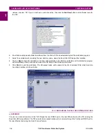
7.
Enter the desired name in the “Device Name” field and a description (optional) of the site.
8.
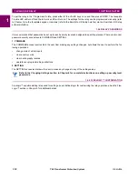
Select “Ethernet” from the
Interface
drop-down list. This will display a number of interface parameters that must be
entered for proper Ethernet functionality.
Figure 1–5: CONFIGURING ETHERNET COMMUNICATIONS
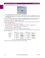
9.
Enter the relay IP address specified in the front panel
SETTINGS
PRODUCT SETUP
COMMUNICATIONS
NET-
WORK
IP ADDRESS
) in the “IP Address” field.
10. Enter the relay slave address and Modbus port address values from the respective settings in the front panel
SETTINGS
PRODUCT SETUP
COMMUNICATIONS
MODBUS PROTOCOL
menu.
11. Click the
Read Order Code
button to connect to the T60 device and upload the order code. If an communications error
occurs, ensure that the three EnerVista UR Setup values entered in the previous steps correspond to the relay setting
values.
12. Click
OK
when the relay order code has been received. The new device will be added to the Site List window (or
Online window) located in the top left corner of the main EnerVista UR Setup window.
The Site Device has now been configured for Ethernet communications. Proceed to the
Connecting to the T60
section to
begin communications.
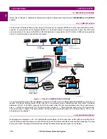
1.3.4 USING THE QUICK CONNECT FEATURE
a) USING QUICK CONNECT VIA THE FRONT PANEL RS232 PORT
Before starting, verify that the serial cable is properly connected from the laptop computer to the front panel RS232 port
with a straight-through 9-pin to 9-pin RS232 cable.
1.
Verify that the latest version of the EnerVista UR Setup software is installed (available from the GE EnerVista CD or
online from
http://www.gedigitalenergy.com/multilin
). See the
Software Installation
section for installation details.
2.
Select the “UR” device from the EnerVista Launchpad to start EnerVista UR Setup.
Summary of Contents for UR T60
Page 10: ...x T60 Transformer Protection System GE Multilin TABLE OF CONTENTS ...
Page 14: ...xiv T60 Transformer Protection System GE Multilin 0 1 BATTERY DISPOSAL 0 BATTERY DISPOSAL 0 ...
Page 34: ...1 20 T60 Transformer Protection System GE Multilin 1 5 USING THE RELAY 1 GETTING STARTED 1 ...
Page 436: ...5 298 T60 Transformer Protection System GE Multilin 5 10 TESTING 5 SETTINGS 5 ...
Page 678: ...C 30 T60 Transformer Protection System GE Multilin C 7 LOGICAL NODES APPENDIX C C ...
Page 688: ...D 10 T60 Transformer Protection System GE Multilin D 1 IEC 60870 5 104 PROTOCOL APPENDIX D D ...
Page 700: ...E 12 T60 Transformer Protection System GE Multilin E 2 DNP POINT LISTS APPENDIX E E ...


