


5-14
T60 Transformer Protection System
GE Multilin
5.2 PRODUCT SETUP
5 SETTINGS
5
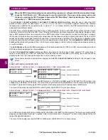
components. The cut-off operation applies to quantities used for metering, protection, and control, as well as those
used by communications protocols. Raw samples of the voltages available via oscillography are not subject cut-off.
The
CURRENT CUT-OFF LEVEL
and the
VOLTAGE CUT-OFF LEVEL
are used to determine the metered power cut-off levels. The
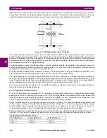
power cut-off level is calculated as shown below. For Delta connections:
(EQ 5.3)
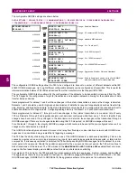
For Wye connections:
(EQ 5.4)
(EQ 5.5)
where VT primary = VT secondary
×
VT ratio and CT primary = CT secondary
×
CT ratio.
For example, given the following settings:
CURRENT CUT-OFF LEVEL
: “0.02 pu”
VOLTAGE CUT-OFF LEVEL
: “1.0 V”
PHASE CT PRIMARY
: “100 A”
PHASE VT SECONDARY
: “66.4 V”
PHASE VT RATIO
: “208.00 : 1"
PHASE VT CONNECTION
: “Delta”.
We have:
CT primary = “100 A”, and
VT primary =
PHASE VT SECONDARY
x
PHASE VT RATIO
= 66.4 V x 208 = 13811.2 V
The power cut-off is therefore:
power cut-off = (
CURRENT CUT-OFF LEVEL
×
VOLTAGE CUT-OFF LEVEL
×
CT primary
×
VT primary)/VT secondary
= (
×
0.02 pu
×
1.0 V
×
100 A
×
13811.2 V) / 66.4 V
= 720.5 watts
Any calculated power value below this cut-off will not be displayed. As well, the three-phase energy data will not accumu-
late if the total power from all three phases does not exceed the power cut-off.
Lower the
VOLTAGE CUT-OFF LEVEL
and
CURRENT CUT-OFF LEVEL
with care as the relay accepts lower signals
as valid measurements. Unless dictated otherwise by a specific application, the default settings of “0.02
pu” for
CURRENT CUT-OFF LEVEL
and “1.0 V” for
VOLTAGE CUT-OFF LEVEL
are recommended.
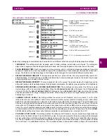
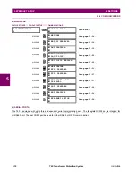
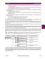
5.2.3 CLEAR RELAY RECORDS
PATH: SETTINGS
PRODUCT SETUP
CLEAR RELAY RECORDS
CLEAR RELAY
RECORDS
CLEAR USER REPORTS:
Off
Range: FlexLogic™ operand
MESSAGE
CLEAR EVENT RECORDS:
Off
Range: FlexLogic™ operand
MESSAGE
CLEAR OSCILLOGRAPHY?
No
Range: FlexLogic™ operand
MESSAGE
CLEAR DATA LOGGER:
Off
Range: FlexLogic™ operand
MESSAGE
CLEAR ARC AMPS 1:
Off
Range: FlexLogic™ operand
MESSAGE
CLEAR ARC AMPS 2:
Off
Range: FlexLogic™ operand
3-phase power cut-off
3
CURRENT CUT-OFF LEVEL
×
VOLTAGE CUT-OFF LEVEL
VT primary
×
CT primary
×
×
VT secondary
------------------------------------------------------------------------------------------------------------------------------------------------------------------------------------------------------------------------------
=
3-phase power cut-off
3
CURRENT CUT-OFF LEVEL
×
VOLTAGE CUT-OFF LEVEL
VT primary
×
CT primary
×
×
VT secondary
--------------------------------------------------------------------------------------------------------------------------------------------------------------------------------------------------------------------------
=
per-phase power cut-off
CURRENT CUT-OFF LEVEL
VOLTAGE CUT-OFF LEVEL
VT primary
×
CT primary
×
×
VT secondary
----------------------------------------------------------------------------------------------------------------------------------------------------------------------------------------------------------------
=
3
NOTE
Summary of Contents for UR T60
Page 10: ...x T60 Transformer Protection System GE Multilin TABLE OF CONTENTS ...
Page 14: ...xiv T60 Transformer Protection System GE Multilin 0 1 BATTERY DISPOSAL 0 BATTERY DISPOSAL 0 ...
Page 34: ...1 20 T60 Transformer Protection System GE Multilin 1 5 USING THE RELAY 1 GETTING STARTED 1 ...
Page 436: ...5 298 T60 Transformer Protection System GE Multilin 5 10 TESTING 5 SETTINGS 5 ...
Page 678: ...C 30 T60 Transformer Protection System GE Multilin C 7 LOGICAL NODES APPENDIX C C ...
Page 688: ...D 10 T60 Transformer Protection System GE Multilin D 1 IEC 60870 5 104 PROTOCOL APPENDIX D D ...
Page 700: ...E 12 T60 Transformer Protection System GE Multilin E 2 DNP POINT LISTS APPENDIX E E ...


