


GE Multilin
L90 Line Current Differential System
3-11
3 HARDWARE
3.2 WIRING
3
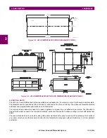
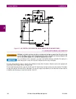
Figure 3–13: CONTROL POWER CONNECTION
3.2.4 CT/VT MODULES
A CT/VT module can have voltage inputs on channels 1 through 4 inclusive, or channels 5 through 8 inclusive. Channels 1
and 5 are intended for connection to phase A, and are labeled as such in the relay. Likewise, channels 2 and 6 are intended
for connection to phase B, and channels 3 and 7 are intended for connection to phase C.
Channels 4 and 8 are intended for connection to a single-phase source. For voltage inputs, these channel are labelled as
auxiliary voltage (VX). For current inputs, these channels are intended for connection to a CT between system neutral and
ground, and are labelled as ground current (IG).
Verify that the connection made to the relay nominal current of 1 A or 5 A matches the secondary rat-
ing of the connected CTs. Unmatched CTs may result in equipment damage or inadequate protec-
tion.
CT/VT modules can be ordered with a standard ground current input that is the same as the phase current input. Each AC
current input has an isolating transformer and an automatic shorting mechanism that shorts the input when the module is
withdrawn from the chassis. There are no internal ground connections on the current inputs. Current transformers with 1 to
50000 A primaries and 1 A or 5 A secondaries may be used.
The above modules are available with enhanced diagnostics. These modules can automatically detect CT/VT hardware
failure and take the relay out of service.
CT connections for both ABC and ACB phase rotations are identical as shown in the
Typical wiring diagram
.
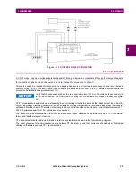
The exact placement of a zero-sequence core balance CT to detect ground fault current is shown below. Twisted-pair
cabling on the zero-sequence CT is recommended.
Summary of Contents for UR Series L90
Page 652: ...A 16 L90 Line Current Differential System GE Multilin A 1 PARAMETER LISTS APPENDIX A A ...
Page 772: ...B 120 L90 Line Current Differential System GE Multilin B 4 MEMORY MAPPING APPENDIX B B ...
Page 802: ...C 30 L90 Line Current Differential System GE Multilin C 7 LOGICAL NODES APPENDIX C C ...
Page 812: ...D 10 L90 Line Current Differential System GE Multilin D 1 IEC 60870 5 104 APPENDIX D D ...
Page 824: ...E 12 L90 Line Current Differential System GE Multilin E 2 DNP POINT LISTS APPENDIX E E ...
Page 834: ...F 10 L90 Line Current Differential System GE Multilin F 3 WARRANTY APPENDIX F F ...
Page 846: ...xii L90 Line Current Differential System GE Multilin INDEX ...