


GE Multilin
L90 Line Current Differential System
10-1
10 APPLICATION OF SETTINGS
10.1 CT REQUIREMENTS
10
10 APPLICATION OF SETTINGS 10.1CT REQUIREMENTS
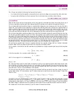
10.1.1 INTRODUCTION
In general, proper CT selection is required to provide both adequate fault sensitivity and prevention of operation on high-
current external faults that could result from CT saturation. The use of high-quality CTs (such as class X) improves relay
stability during transients and CT saturation and can increase relay sensitivity. A current differential scheme is highly
dependent on adequate signals from the source CTs. Ideally, CTs selected for line current differential protection should be
based on the criteria described below. If the available CTs do not meet the described criteria, the L90 will still provide good
security for CT saturation for external faults. The L90 adaptive restraint characteristics, based on estimates of measure-
ment errors and CT saturation detection, allow the relay to be secure on external faults while maintaining excellent perfor-
mance for severe internal faults. Where CT characteristics do not meet criteria or where CTs at both ends may have
different characteristics, the differential settings should be adjusted as per section 9.2.1.
The capability of the CTs, and the connected burden, should be checked as follows:
1.
The CTs should be class TPX or TPY (class TPZ should only be used after discussion with both the manufacturer of
the CT and GE Multilin) or IEC class 5P20 or better.
2.
The CT primary current rating should be somewhat higher than the maximum continuous current, but not extremely
high relative to maximum load because the differential element minimum sensitivity setting is approximately 0.2
CT
rating (the L90 relay allows for different CT ratings at each of the terminals).
3.
The VA rating of the CTs should be above the Secondary Burden
CT Rated Secondary Current. The maximum sec-
ondary burden for acceptable performance is:
(EQ 10.1)
where:
R
b
= total (two-way) wiring resistance plus any other load
R
r
= relay burden at rated secondary current
4.
The CT kneepoint voltage (per the
V
k
curves from the manufacturer) should be higher than the maximum secondary
voltage during a fault. This can be estimated by:
(EQ 10.2)
where:
I
fp
= maximum secondary phase-phase fault current
I
fg
= maximum secondary phase-ground fault current
X
/
R
= primary system reactance / resistance ratio
R
CT
= CT secondary winding resistance
R
L
= AC secondary wiring resistance (one-way)
10.1.2 CALCULATION EXAMPLE 1
This example illustrates how to check the performance of a class C400 ANSI/IEEE CT, ratios 2000/1800/1600/1500 : 5 A
connected at 1500:5. The burden and kneepoints are verified in this example.
Given the following values:
•
maximum
I
fp
= 14 000 A
•
maximum
I
fg
= 12 000 A
•
impedance angle of source and line = 78°
•
CT secondary leads are 75 m of AWG 10.
The following procedure verifies the burden. ANSI/IEEE class C400 requires that the CT can deliver 1 to 20 times the rated
secondary current to a standard B-4 burden (4 ohms or lower) without exceeding a maximum ratio error of 10%.
1.
The maximum allowed burden at the 1500/5 tap is
.
2.
The
R
CT
,
R
r
, and
R
L
values are calculated as:
R
b
R
r
CT Rated VA
CT Secondary
I
rated
2
-------------------------------------------------------------
V
k
I
fp
X
R
----
1
R
CT
R
L
R
r
for phase-phase faults
V
k
I
fg
X
R
----
1
R
CT
2
R
L
R
r
for phase-ground faults
1500 2000
4
3
Summary of Contents for UR Series L90
Page 652: ...A 16 L90 Line Current Differential System GE Multilin A 1 PARAMETER LISTS APPENDIX A A ...
Page 772: ...B 120 L90 Line Current Differential System GE Multilin B 4 MEMORY MAPPING APPENDIX B B ...
Page 802: ...C 30 L90 Line Current Differential System GE Multilin C 7 LOGICAL NODES APPENDIX C C ...
Page 812: ...D 10 L90 Line Current Differential System GE Multilin D 1 IEC 60870 5 104 APPENDIX D D ...
Page 824: ...E 12 L90 Line Current Differential System GE Multilin E 2 DNP POINT LISTS APPENDIX E E ...
Page 834: ...F 10 L90 Line Current Differential System GE Multilin F 3 WARRANTY APPENDIX F F ...
Page 846: ...xii L90 Line Current Differential System GE Multilin INDEX ...