


4-14
L90 Line Current Differential System
GE Multilin
4.3 FACEPLATE INTERFACE
4 HUMAN INTERFACES
4
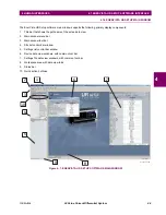
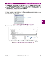
The following figure shows the vertical arrangement of the faceplate panels for relays ordered with the vertical option.
Figure 4–17: UR-SERIES STANDARD VERTICAL FACEPLATE PANELS
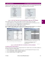
4.3.2 LED INDICATORS
a) ENHANCED FACEPLATE
The enhanced front panel display provides five columns of LED indicators. The first column contains 14 status and event
cause LEDs, and the next four columns contain the 48 user-programmable LEDs.
The RESET key is used to reset any latched LED indicator or target message, once the condition has been cleared (these
latched conditions can also be reset via the
SETTINGS
INPUT/OUTPUTS
RESETTING
menu). The RS232 port is
intended for connection to a portable PC.
The USER keys are used by the breaker control feature.
Figure 4–18: TYPICAL LED INDICATOR PANEL FOR ENHANCED FACEPLATE
The status indicators in the first column are described below.
•
IN SERVICE
:
This LED indicates that control power is applied, all monitored inputs, outputs, and internal systems are
OK, and that the device has been programmed.
842811A1.CDR
Summary of Contents for UR Series L90
Page 652: ...A 16 L90 Line Current Differential System GE Multilin A 1 PARAMETER LISTS APPENDIX A A ...
Page 772: ...B 120 L90 Line Current Differential System GE Multilin B 4 MEMORY MAPPING APPENDIX B B ...
Page 802: ...C 30 L90 Line Current Differential System GE Multilin C 7 LOGICAL NODES APPENDIX C C ...
Page 812: ...D 10 L90 Line Current Differential System GE Multilin D 1 IEC 60870 5 104 APPENDIX D D ...
Page 824: ...E 12 L90 Line Current Differential System GE Multilin E 2 DNP POINT LISTS APPENDIX E E ...
Page 834: ...F 10 L90 Line Current Differential System GE Multilin F 3 WARRANTY APPENDIX F F ...
Page 846: ...xii L90 Line Current Differential System GE Multilin INDEX ...