


10-2
L90 Line Current Differential System
GE Multilin
10.1 CT REQUIREMENTS
10 APPLICATION OF SETTINGS
10
(EQ 10.3)
3.
This gives a total burden of:
.
(EQ 10.4)
4.
This is less than the allowed 3
, which is OK.
The following procedure verifies the kneepoint voltage.
1.
The maximum voltage available from the
.
2.
The system X/R ratio
.
3.
The CT voltage for maximum phase fault is:
(EQ 10.5)
4.
The CT voltage for maximum ground fault is:
(EQ 10.6)
5.
The CT will provide acceptable performance in this application.
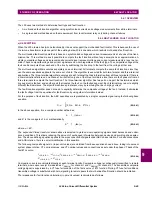
10.1.3 CALCULATION EXAMPLE 2
To check the performance of an IEC CT of class 5P20, 15 VA, ratio 1500:5 A, assume the following values:
•
maximum
I
fp
= 14 000 A
•
maximum
I
fg
= 12 000 A
•
impedance angle of source and line = 78°
•
CT secondary leads are 75 m of AWG 10.
The IEC rating requires the CT deliver up to 20 times the rated secondary current without exceeding a maximum ratio error
of 5%, to a burden of:
(EQ 10.7)
The total Burden =
R
r
+
R
l
= 0.008 + 0.52 = 0.528
, which is less than the allowed 0.6
, which is OK.
The following procedure verifies the kneepoint voltage.
1.
The maximum voltage available from the
.
2.
The system X/R ratio
.
3.
The CT voltage for maximum phase fault is:
(EQ 10.8)
4.
The CT voltage for maximum ground fault is:
(EQ 10.9)
5.
The CT will provide acceptable performance in this application.
R
CT
0.75
R
r
0.2 VA
5 A
2
------------------
0.008
R
L
2 75 m
3.75
1000 m
--------------------
2 0.26
0.528
Total Burden
R
CT
R
r
R
L
0.75
0.008
0.52
1.28
CT
1500 2000
400
300 V
78
tan
4.71
V
14000 A
ratio of 300:1
-----------------------------------
4.71 1
0.75 0.26 0.008
271.26 V (< 300 V, which is OK)
V
12000 A
ratio of 300:1
-----------------------------------
4.71 1
0.75 0.52 0.008
291.89 V (< 300 V, which is OK)
Burden
15 VA
5 A
2
----------------
0.6
at the 5 A rated current
CT
1500 2000
400
300 V
78
tan
4.71
V
14000 A
ratio of 300:1
-----------------------------------
4.71 1
0.75 0.26 0.008
271.26 V (< 300 V, which is OK)
V
12000 A
ratio of 300:1
-----------------------------------
4.71 1
0.75 0.52 0.008
291.89 V (< 300 V, which is OK)
Summary of Contents for UR Series L90
Page 652: ...A 16 L90 Line Current Differential System GE Multilin A 1 PARAMETER LISTS APPENDIX A A ...
Page 772: ...B 120 L90 Line Current Differential System GE Multilin B 4 MEMORY MAPPING APPENDIX B B ...
Page 802: ...C 30 L90 Line Current Differential System GE Multilin C 7 LOGICAL NODES APPENDIX C C ...
Page 812: ...D 10 L90 Line Current Differential System GE Multilin D 1 IEC 60870 5 104 APPENDIX D D ...
Page 824: ...E 12 L90 Line Current Differential System GE Multilin E 2 DNP POINT LISTS APPENDIX E E ...
Page 834: ...F 10 L90 Line Current Differential System GE Multilin F 3 WARRANTY APPENDIX F F ...
Page 846: ...xii L90 Line Current Differential System GE Multilin INDEX ...