


GE Multilin
L90 Line Current Differential System
9-53
9 THEORY OF OPERATION
9.6 FAULT LOCATOR
9
•
Relay 1: 0.38781 pu
0.26811°
•
Relay 2: 0.30072 pu
–
12.468°
•
Relay 3: 0.37827 pu
8.9388°
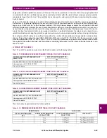
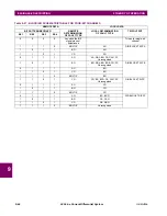
Since they have a common per-unit base, the composite voltages are used at all locations. The currents are ratio matched
using the tap settings.
For example, the composite current at relay 1 is 1.3839 pu of its local CT; that is, 1.3839 × 1200 A = 1.6607 kA. When cal-
culated at relay 2 from the data sent from relay 1 to relay 2, this value is 1.6607 kA / 1000 A = 1.6607 pu of the relay 2 CT.
This is due to the procedure of applying tap settings to the received phase currents before calculating the composite signal.
As a result, the three relays work with the following signals.
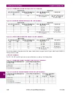
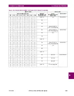
The line impedances entered in secondary ohms are recalculated as follows (refer to the previous sub-section for equa-
tions).
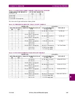
Using the data in the previous two tables, the tap voltages are calculated as follows (refer to the previous sub-section for
equations).
From the above table, it is already visible that:
•
Looking from relay 1 there is no fault between the tap and the local terminal and between the tap and remote 2 termi-
nal. Therefore, the fault must be between the remote 1 terminal = relay 2 and the tap.
•
Looking from relay 2 there is no fault between the tap and the remote 1 terminal, and between the tap and remote 2
terminal. Therefore, the fault must be between the local terminal = relay 2 and the tap.
•
Looking from relay 3 there is no fault between the tap and the remote 1 terminal, and between the tap and the local ter-
minal. Therefore, the fault must be between the remote 2 terminal = relay 2 and the tap.
Note that the correct value of the tap voltage is equal for all three relays. This is expected since the per-unit base for the
composite voltages is equal for all three relays.
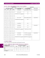
The three relays calculate the differences as follows (refer to the previous sub-section for equations).
Table 9–37: COMPOSITE SIGNALS AT ALL THREE RELAYS
VALUE
RELAY 1
RELAY 2
RELAY 3
V
LOC
(
X
)
0.38781 pu
0.26811°
0.30072 pu
–12.468°
0.37827 pu
8.9388°
V
REM
1(
X
)
0.30072 pu
–12.468°
0.38781 pu
0.26811°
0.38781 pu
0.26811°
V
REM
2(
X
)
0.37827 pu
8.9388°
0.37827 pu
8.9388°
0.30072 pu
–12.468°
I
LOC
(
X
)
1.3839 pu
–84.504°
5.4844 pu
–85.236°
1.2775 pu
–56.917°
I
REM
1(
X
)
4.5704 pu
–85.236°
1.6607 pu
–84.504°
1.0379 pu
–84.504°
I
REM
2(
X
)
1.7033 pu
–56.917°
2.0439 pu
–56.917°
3.4278 pu
–85.236°
Table 9–38: PER-UNIT LINE IMPEDANCE
VALUE
RELAY 1
RELAY 2
RELAY 3
Local to tap
0.088509 pu
80.5°
0.12644 pu
80.5°
0.092735 pu
80.5°
Remote 1 to tap
0.15174 pu
80.5°
0.073754 pu
80.5°
0.11801 pu
80.5°
Remote 2 to tap
0.069551 pu
80.5°
0.057957 pu
80.5°
0.20232 pu
80.5°
Table 9–39: CALCULATED TAP VOLTAGES USING TERMINAL DATA
VALUE
RELAY 1
RELAY 2
RELAY 3
V
T
(
LOC
)
0.26581 pu
2.2352°
0.39755 pu
–178.9°
0.26535 pu
2.4583°
V
T
(
REM
1)
0.39758 pu
–178.9°
0.26582 pu
2.2351°
0.26581 pu
2.2352°
V
T
(
REM
2)
0.26535 pu
2.4583°
0.26535 pu
2.4587°
0.39758 pu
–178.9°
Summary of Contents for UR Series L90
Page 652: ...A 16 L90 Line Current Differential System GE Multilin A 1 PARAMETER LISTS APPENDIX A A ...
Page 772: ...B 120 L90 Line Current Differential System GE Multilin B 4 MEMORY MAPPING APPENDIX B B ...
Page 802: ...C 30 L90 Line Current Differential System GE Multilin C 7 LOGICAL NODES APPENDIX C C ...
Page 812: ...D 10 L90 Line Current Differential System GE Multilin D 1 IEC 60870 5 104 APPENDIX D D ...
Page 824: ...E 12 L90 Line Current Differential System GE Multilin E 2 DNP POINT LISTS APPENDIX E E ...
Page 834: ...F 10 L90 Line Current Differential System GE Multilin F 3 WARRANTY APPENDIX F F ...
Page 846: ...xii L90 Line Current Differential System GE Multilin INDEX ...