9-48
L90 Line Current Differential System
GE Multilin
9.5 SINGLE-POLE TRIPPING
9 THEORY OF OPERATION
9
9.5.6 CROSS-COUNTRY FAULT EXAMPLE
Assume a single pole operation application where L90 relays are used to protect a two terminal line, (terminals T1 and T2)
using phase and ground distance zone 1, 2 and 3 elements in a permissive over-reaching transfer trip scheme. The perfor-
mance of the system with one- two and four-bit communications channels is outlined for a mid-line phase A-to-ground fault
and a co-incident phase B-to-ground fault just behind terminal T2. Assume also that the reclosers are enabled and reset.
At T1 the following protection elements will pickup:
•
Ground Distance Zone 1, 2, and 3 for an AG fault
•
Ground Distance Zone 2 and 3 for a BG fault
•
Phase Distance Zone 2 and 3 for an AB fault
At T1 the phase selector will determine the fault is type ABG. This response is independent from the distance elements –
the Phase Selector sees two forward faults.
At T2 the following protection elements will pickup:
•
Ground Distance Zone 1, 2, and 3 for an AG fault
At T2 the phase selector will determine the fault is type AG. The reverse BG fault is likely to be ignored.
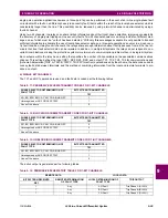
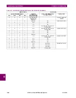
If a one-bit channel is used, terminal T1 will trip three poles but terminal T2 will trip phase A only, (see the Tables below)
which is undesirable.
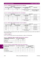
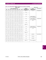
If a two-bit channel is used both terminals will trip phase A only, (see the Tables below) which is the desired outcome.
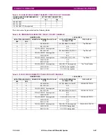
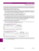
If a four-bit channel is used both terminals will trip phase A only, (see the Tables below) which is the desired outcome.
TERMINAL
REMOTE DATA
LOCAL DATA
BIT PATTERN RECEIVED
REMOTE DETERMINATION
OF FAULT TYPE
LOCAL DETERMINATION
OF FAULT TYPE
TRIP OUTPUT
RX1
T1
1
Any
MULTI-P (ABG)
Trip Three Phases
T2
1
Any
AG
Trip Phase A
TERMINAL
REMOTE DATA
LOCAL DATA
BIT PATTERN RECEIVED
REMOTE DETERMINATION
OF FAULT TYPE
LOCAL DETERMINATION
OF FAULT TYPE
TRIP OUTPUT
RX1
RX2
T1
1
0
AG
ABG
Trip Phase A
T2
1
1
ABG
AG
Trip Phase A
TERMINAL
REMOTE DATA
LOCAL DATA
BIT PATTERN RECEIVED REMOTE DETERMINATION
OF FAULT TYPE
LOCAL DETERMINATION
OF FAULT TYPE
TRIP OUTPUT
RX1
RX2
RX3
RX4
T1
0
0
0
1
AG
ABG
Trip Phase A
T2
1
0
0
0
ABG
AG
Trip Phase A
Summary of Contents for UR Series L90
Page 652: ...A 16 L90 Line Current Differential System GE Multilin A 1 PARAMETER LISTS APPENDIX A A ...
Page 772: ...B 120 L90 Line Current Differential System GE Multilin B 4 MEMORY MAPPING APPENDIX B B ...
Page 802: ...C 30 L90 Line Current Differential System GE Multilin C 7 LOGICAL NODES APPENDIX C C ...
Page 812: ...D 10 L90 Line Current Differential System GE Multilin D 1 IEC 60870 5 104 APPENDIX D D ...
Page 824: ...E 12 L90 Line Current Differential System GE Multilin E 2 DNP POINT LISTS APPENDIX E E ...
Page 834: ...F 10 L90 Line Current Differential System GE Multilin F 3 WARRANTY APPENDIX F F ...
Page 846: ...xii L90 Line Current Differential System GE Multilin INDEX ...


