


9-32
L90 Line Current Differential System
GE Multilin
9.4 PHASE DISTANCE APPLIED TO POWER TRANSFORMERS
9 THEORY OF OPERATION
9
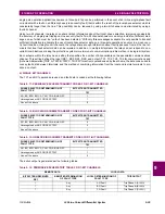
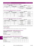
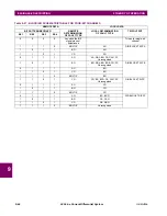
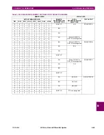
Equations from the “Current Transformation” and “Voltage Transformation” columns are used to derive inputs to the three
(AB, BC, and CA) phase distance elements. For example, if the CTs are located at the delta side of the Delta-Wye 11 trans-
former, and a given zone is set to look through the transformer into the system connected to the Wye winding, the CT loca-
tion setting for that zone shall be set to Dy11 and the relay would use
instead of a traditional
for the AB
phase distance element.
The current supervision pickup setting applies to the currents specified in the “Current Transformation” columns.
A distance zone originates at the location of the VTs (regardless of the location of the CTs). For more information on set-
tings please refer to Chapter 9: Application of Settings.
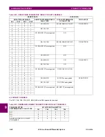
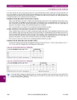
9.4.2 EXAMPLE
Consider the system shown below:
Figure 9–12: SAMPLE SYSTEM CONFIGURATION
Normally, in order to respond to the fault shown in the figure, a distance relay shall be applied at the relaying point X. The
relay input signals at this location are shown in the following table.
Yd9
AB
BC
CA
Yd11
AB
BC
CA
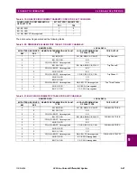
Table 9–10: PHASE DISTANCE INPUT SIGNALS FOR WYE-DELTA TRANSFORMERS
TRANSFORMER
CONNECTION
LOOP
CURRENT
TRANSFORMATION
VOLTAGE
TRANSFORMATION
I
AB
_21
P
1
3
-------
2
I
C
I
A
I
B
V
AB
_21
P
3
V
C
I
BC
_21
P
1
3
-------
2
I
A
I
B
I
C
V
BC
_21
P
3
V
A
I
CA
_21
P
1
3
-------
2
I
B
I
A
I
C
V
CA
_21
P
3
V
B
I
AB
_21
P
1
3
-------
I
A
I
C
2
I
B
V
AB
_21
P
3
V
B
I
BC
_21
P
1
3
-------
I
A
I
B
2
I
C
V
BC
_21
P
3
V
C
I
CA
_21
P
1
3
-------
I
B
I
C
2
I
A
V
CA
_21
P
3
V
A
3
I
B
I
A
I
B
837727A2.CDR
AB
wye, 330 lag
°
0.688
85°
Ω∠
2.57
Ω∠
88.4°
150 MVA, 10%
13.8kV/315kV
Z = 30.11
85°
L
Ω∠
VT = 315kV/120V
CT = 300:5
VT = 13.8kV/120V
CT = 8000:5
delta
H
X
Summary of Contents for UR Series L90
Page 652: ...A 16 L90 Line Current Differential System GE Multilin A 1 PARAMETER LISTS APPENDIX A A ...
Page 772: ...B 120 L90 Line Current Differential System GE Multilin B 4 MEMORY MAPPING APPENDIX B B ...
Page 802: ...C 30 L90 Line Current Differential System GE Multilin C 7 LOGICAL NODES APPENDIX C C ...
Page 812: ...D 10 L90 Line Current Differential System GE Multilin D 1 IEC 60870 5 104 APPENDIX D D ...
Page 824: ...E 12 L90 Line Current Differential System GE Multilin E 2 DNP POINT LISTS APPENDIX E E ...
Page 834: ...F 10 L90 Line Current Differential System GE Multilin F 3 WARRANTY APPENDIX F F ...
Page 846: ...xii L90 Line Current Differential System GE Multilin INDEX ...