GE Multilin
L90 Line Current Differential System
5-77
5 SETTINGS
5.2 PRODUCT SETUP
5
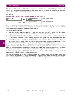
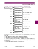
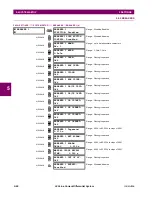
An example user display setup and result is shown below:
If the parameters for the top line and the bottom line items have the same units, then the unit is displayed on the
bottom line only. The units are only displayed on both lines if the units specified both the top and bottom line items
are different.
5.2.18 INSTALLATION
PATH: SETTINGS
PRODUCT SETUP
INSTALLATION
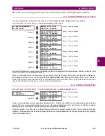
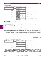
To safeguard against the installation of a relay without any entered settings, the unit will not allow signaling of any output
relay until
RELAY SETTINGS
is set to "Programmed". This setting is defaulted to "Not Programmed" when at the factory. The
UNIT NOT PROGRAMMED
self-test error message is displayed until the relay is put into the "Programmed" state.
The
RELAY NAME
setting allows the user to uniquely identify a relay. This name will appear on generated reports.
USER DISPLAY 1
DISP 1 TOP LINE:
Current X ~
A
Shows user-defined text with first tilde marker.
MESSAGE
DISP 1 BOTTOM LINE:
Current Y ~
A
Shows user-defined text with second tilde marker.
MESSAGE
DISP 1 ITEM 1:
6016
Shows decimal form of user-selected Modbus register
address, corresponding to first tilde marker.
MESSAGE
DISP 1 ITEM 2:
6357
Shows decimal form of user-selected Modbus register
address, corresponding to second tilde marker.
MESSAGE
DISP 1 ITEM 3:
0
This item is not being used. There is no corresponding
tilde marker in top or bottom lines.
MESSAGE
DISP 1 ITEM 4:
0
This item is not being used. There is no corresponding
tilde marker in top or bottom lines.
MESSAGE
DISP 1 ITEM 5:
0
This item is not being used. There is no corresponding
tilde marker in top or bottom lines.
USER
DISPLAYS
Current X 0.850
Current Y 0.327 A
Shows the resultant display content.
INSTALLATION
RELAY SETTINGS:
Not Programmed
Range: Not Programmed, Programmed
MESSAGE
RELAY NAME:
Relay-1
Range: up to 20 alphanumeric characters
NOTE
Summary of Contents for UR Series L90
Page 652: ...A 16 L90 Line Current Differential System GE Multilin A 1 PARAMETER LISTS APPENDIX A A ...
Page 772: ...B 120 L90 Line Current Differential System GE Multilin B 4 MEMORY MAPPING APPENDIX B B ...
Page 802: ...C 30 L90 Line Current Differential System GE Multilin C 7 LOGICAL NODES APPENDIX C C ...
Page 812: ...D 10 L90 Line Current Differential System GE Multilin D 1 IEC 60870 5 104 APPENDIX D D ...
Page 824: ...E 12 L90 Line Current Differential System GE Multilin E 2 DNP POINT LISTS APPENDIX E E ...
Page 834: ...F 10 L90 Line Current Differential System GE Multilin F 3 WARRANTY APPENDIX F F ...
Page 846: ...xii L90 Line Current Differential System GE Multilin INDEX ...

