


5-70
F35 Multiple Feeder Protection System
GE Multilin
5.2 PRODUCT SETUP
5 SETTINGS
5
The
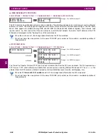
DAYLIGHT SAVINGS TIME (DST)
settings can be used to allow the relay to follow the DST rules of the local time zone.
Note that when IRIG-B time synchronization is active, the local time in the IRIG-B signal contains any daylight savings time
offset and so the DST settings are ignored.
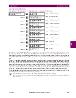
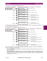
5.2.7 FAULT REPORTS
PATH: SETTINGS
PRODUCT SETUP
FAULT REPORTS
FAULT REPORT 1(5)
The F35 relay supports one fault report and an associated fault locator per CT bank to a maximum of 5. The signal source
and trigger condition, as well as the characteristics of the line or feeder, are entered in this menu.
The fault report stores data, in non-volatile memory, pertinent to an event when triggered. The captured data contained in
the
FaultReport.txt
file includes:
•
Fault report number.
•
Name of the relay, programmed by the user.
•
Firmware revision of the relay.
•
Date and time of trigger.
•
Name of trigger (specific operand).
•
Line or feeder ID via the name of a configured signal source.
•
Active setting group at the time of trigger.
•
Pre-fault current and voltage phasors (two cycles before either a 50DD disturbance associated with fault report source
or the trigger operate). Once a disturbance is detected, pre-fault phasors hold for 3 seconds waiting for the fault report
trigger. If trigger does not occur within this time, the values are cleared to prepare for the next disturbance.
•
Fault current and voltage phasors (one cycle after the trigger).
•
Elements operated at the time of triggering.
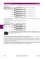
FAULT REPORT 1
FAULT REPORT 1
SOURCE: SRC 1
Range: SRC 1, SRC 2, SRC 3, SRC 4, SRC 5, SRC 6
MESSAGE
FAULT REPORT 1 TRIG:
Off
Range: FlexLogic operand
MESSAGE
FAULT REPORT 1 Z1
MAG: 3.00
Ω
Range: 0.01 to 250.00 ohms in steps of 0.01
MESSAGE
FAULT REPORT 1 Z1
ANGLE: 75°
Range: 25 to 90° in steps of 1
MESSAGE
FAULT REPORT 1 Z0
MAG: 9.00
Ω
Range: 0.01 to 650.00 ohms in steps of 0.01
MESSAGE
FAULT REPORT 1 Z0
ANGLE: 75°
Range: 25 to 90° in steps of 1
MESSAGE
FAULT REPORT 1 LINE
LENGTH UNITS: km
Range: km, miles
MESSAGE
FAULT REP 1 LENGTH
(km
): 100.0
Range: 0.0 to 2000.0 in steps of 0.1
MESSAGE
FAULT REPORT 1 VT
SUBSTITUTION: None
Range: None, I0, V0
MESSAGE
FAULT REP 1 SYSTEM
Z0 MAG: 2.00
Ω
Range: 0.01 to 650.00 ohms in steps of 0.01
MESSAGE
FAULT REP 1 SYSTEM
Z0 ANGLE: 75°
Range: 25 to 90° in steps of 1
Summary of Contents for UR F35 Series
Page 10: ...x F35 Multiple Feeder Protection System GE Multilin TABLE OF CONTENTS ...
Page 366: ...5 238 F35 Multiple Feeder Protection System GE Multilin 5 10 TESTING 5 SETTINGS 5 ...
Page 426: ...10 12 F35 Multiple Feeder Protection System GE Multilin 10 6 DISPOSAL 10 MAINTENANCE 10 ...
Page 454: ...A 28 F35 Multiple Feeder Protection System GE Multilin A 1 PARAMETER LISTS APPENDIX A A ...
Page 620: ...F 12 F35 Multiple Feeder Protection System GE Multilin F 2 DNP POINT LISTS APPENDIX F F ...
Page 630: ...H 8 F35 Multiple Feeder Protection System GE Multilin H 3 WARRANTY APPENDIX H H ...
Page 640: ...x F35 Multiple Feeder Protection System GE Multilin INDEX ...