9-4
Transport Pro
Revision A
2012659-042
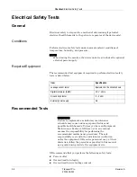
Checkout: Electrical Safety Tests
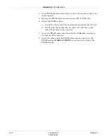
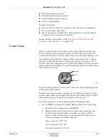
Readings other than these indicate improper wiring. Have the
wall receptacle checked by an electrician.
2. Use a DMM to measure the ground-to-neutral loop resistance.
CAUTION
DO NOT check the ground-neutral loop resistance unless
the wall receptacle is correctly wired.
a. Select the milliohms (m
Ω
) scale on the DMM.
b. Measure resistance across the power cord ground and neutral.
c. Measure from the ground lug on the rear power connector to any
exposed metal of the monitor. The resistance between the ground
and neutral connections, after the ohmmeter is nulled, must be
less than 100 m
Ω
. If not, have the wall receptacle checked by an
electrician.
Ground (Earth) Integrity
Listed below are two methods for checking the ground (earth) integrity,
“Ground Continuity” and “Impedance of Protective Earth Connection.”
These tests determine whether the device's exposed metal and power
inlet's earth (ground) connection has a power ground fault condition.
Perform the test method below that is required by your Country/Local
governing safety organization.
NOTE
When testing the monitor, the device under test includes the optional
external power supply.
Ground Continuity
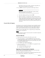
1. Disconnect the device under test from the power outlet.
2. Connect the negative (-) lead of the DMM to the protective earth
terminal (ground pin in power inlet connector) or the protective earth
pin in the Mains plug (ground pin in power cord). Refer to the US 120
V AC power cord figure above.
3. Set the DMM to the milliohm (m
Ω
) range.
4. Connect the positive (+) lead of the DMM to the equipotential stud.
Resistance must read:
0.1 ohm or less without power cord
0.2 ohms or less with power cord
Impedance of Protective Earth Connection
This test unlike a ground continuity test will also stress the ground
system by using special ground bond testers.
This test normally is only required as a manufacturing production test to
receive safety agency compliance (i.e. EN 60601-1).
Summary of Contents for Transport Pro
Page 1: ...Transport Pro Patient Monitor Service Manual Software Version 2 2024579 018 Revision A ...
Page 9: ...Revision A Transport Pro 1 1 2012659 042 1 Introduction ...
Page 12: ...1 4 Transport Pro Revision A 2012659 042 Introduction Safety Message Definitions ...
Page 13: ...Revision A Transport Pro 2 1 2012659 042 2 Equipment Overview ...
Page 28: ...2 16 Transport Pro Revision A 2012659 042 Equipment Overview Theory of Operation ...
Page 29: ...Revision A Transport Pro 3 1 2012659 042 3 Installation ...
Page 33: ...Revision A Transport Pro 4 1 2012659 042 4 Configuration ...
Page 38: ...4 6 Transport Pro Revision A 2012659 042 Configuration Monitor Settings ...
Page 39: ...Revision A Transport Pro 5 1 2012659 042 5 Maintenance ...
Page 47: ...Revision A Transport Pro 6 1 2012659 042 6 Troubleshooting ...
Page 57: ...Revision A Transport Pro 7 1 2012659 042 7 Ordering Parts ...
Page 59: ...Revision A Transport Pro 7 3 2012659 042 Ordering Parts Exploded View Exploded View 622A ...
Page 62: ...7 6 Transport Pro Revision A 2012659 042 Ordering Parts Hardware ...
Page 63: ...Revision A Transport Pro 8 1 2012659 042 8 Disassembly ...
Page 83: ...Revision A Transport Pro 9 1 2012659 042 9 Checkout ...
Page 97: ...Revision A Transport Pro A 1 2012659 042 A Technical Specifications ...
Page 100: ...A 4 Transport Pro Revision A 2012659 042 Technical Specifications External Power Supply ...
Page 101: ...Revision A Transport Pro B 1 2012659 042 B Electromagnetic Compatibility ...
Page 109: ......

