5-164
T35 Transformer Protection System
GE Multilin
5.8 INPUTS AND OUTPUTS
5 SETTINGS
5
5.8INPUTS AND OUTPUTS
5.8.1 CONTACT INPUTS
PATH: SETTINGS
INPUTS/OUTPUTS
CONTACT INPUTS
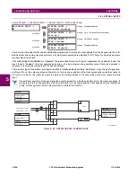
The contact inputs menu contains configuration settings for each contact input as well as voltage thresholds for each group
of four contact inputs. Upon startup, the relay processor determines (from an assessment of the installed modules) which
contact inputs are available and then display settings for only those inputs.
An alphanumeric ID may be assigned to a contact input for diagnostic, setting, and event recording purposes. The
CON-
TACT IP X On
” (Logic 1) FlexLogic operand corresponds to contact input “X” being closed, while
CONTACT IP X Off
corre-
sponds to contact input “X” being open. The
CONTACT INPUT DEBNCE TIME
defines the time required for the contact to
overcome ‘contact bouncing’ conditions. As this time differs for different contact types and manufacturers, set it as a maxi-
mum contact debounce time (per manufacturer specifications) plus some margin to ensure proper operation. If
CONTACT
INPUT EVENTS
is set to “Enabled”, every change in the contact input state will trigger an event.
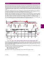
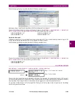
A raw status is scanned for all Contact Inputs synchronously at the constant rate of 0.5 ms as shown in the figure below.
The DC input voltage is compared to a user-settable threshold. A new contact input state must be maintained for a user-
settable debounce time in order for the T35 to validate the new contact state. In the figure below, the debounce time is set
at 2.5 ms; thus the 6th sample in a row validates the change of state (mark no. 1 in the diagram). Once validated (de-
bounced), the contact input asserts a corresponding FlexLogic operand and logs an event as per user setting.
A time stamp of the first sample in the sequence that validates the new state is used when logging the change of the con-
tact input into the Event Recorder (mark no. 2 in the diagram).
Protection and control elements, as well as FlexLogic equations and timers, are executed eight times in a power system
cycle. The protection pass duration is controlled by the frequency tracking mechanism. The FlexLogic operand reflecting
the debounced state of the contact is updated at the protection pass following the validation (marks no. 3 and 4 on the fig-
ure below). The update is performed at the beginning of the protection pass so all protection and control functions, as well
as FlexLogic equations, are fed with the updated states of the contact inputs.
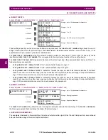
CONTACT INPUTS
CONTACT INPUT H5a
MESSAGE
CONTACT INPUT H5a ID:
Cont Ip 1
Range: up to 12 alphanumeric characters
MESSAGE
CONTACT INPUT H5a
DEBNCE TIME: 2.0 ms
Range: 0.0 to 16.0 ms in steps of 0.5
MESSAGE
CONTACT INPUT H5a
EVENTS: Disabled
Range: Disabled, Enabled
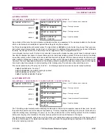
↓
CONTACT INPUT xxx
CONTACT INPUT
THRESHOLDS
MESSAGE
Ips H5a,H5c,H6a,H6c
THRESHOLD: 33 Vdc
Range: 17, 33, 84, 166 Vdc
MESSAGE
Ips H7a,H7c,H8a,H8c
THRESHOLD: 33 Vdc
Range: 17, 33, 84, 166 Vdc
↓
MESSAGE
Ips xxx,xxx,xxx,xxx
THRESHOLD: 33 Vdc
Range: 17, 33, 84, 166 Vdc
Summary of Contents for T35 UR Series
Page 10: ...x T35 Transformer Protection System GE Multilin TABLE OF CONTENTS ...
Page 48: ...2 18 T35 Transformer Protection System GE Multilin 2 2 SPECIFICATIONS 2 PRODUCT DESCRIPTION 2 ...
Page 314: ...5 192 T35 Transformer Protection System GE Multilin 5 10 TESTING 5 SETTINGS 5 ...
Page 338: ...6 24 T35 Transformer Protection System GE Multilin 6 5 PRODUCT INFORMATION 6 ACTUAL VALUES 6 ...
Page 350: ...7 12 T35 Transformer Protection System GE Multilin 7 2 TARGETS 7 COMMANDS AND TARGETS 7 ...
Page 366: ...8 16 T35 Transformer Protection System GE Multilin 8 2 CYBERSENTRY 8 SECURITY 8 ...
Page 406: ...A 14 T35 Transformer Protection System GE Multilin A 1 PARAMETER LISTS APPENDIX A A ...
Page 540: ...D 10 T35 Transformer Protection System GE Multilin D 1 IEC 60870 5 104 PROTOCOL APPENDIX D D ...
Page 552: ...E 12 T35 Transformer Protection System GE Multilin E 2 DNP POINT LISTS APPENDIX E E ...
Page 560: ...F 8 T35 Transformer Protection System GE Multilin F 3 WARRANTY APPENDIX F F ...

