


4–6
345 TRANSFORMER PROTECTION SYSTEM – INSTRUCTION MANUAL
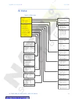
A1 STATUS
CHAPTER 4: ACTUAL VALUES
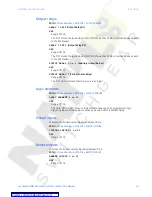
Remote outputs
The state of all active remote outputs is displayed here.
PATH
:
ACTUAL VALUES > A1 STATUS > REMOTE OUTPUTS
REMOTE OUTPUTS 1 to 32
OFF
Range: Off, On
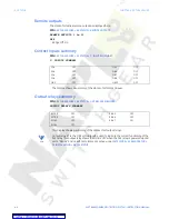
Contact inputs summary
PATH
:
ACTUAL VALUES > A1 STATUS > C. INPUTS SUMMARY
C. INPUTS SUMMARY
The display shows a summary of the states of all contact inputs.
Output relays summary
PATH
:
ACTUAL VALUES > A1 STATUS > OUT RELAYS SUMMARY
OUTPUT RELAYS SUMMARY
This display shows a summary of the states of all output relays.
NOTE
NOTE:
Output relay #7 is the Critical Failure relay, used to indicate the correct functioning of the
345 relay. This output relay shows the status "ON" when the 345 relay is powered up and
set to "Ready" and no self-test alarms are active, under
SETPOINTS > S1 RELAY SETUP >
S1 INSTALLATION > RELAY STATUS.
52a
OFF
CI#5
OFF
52b
OFF
CI#6
OFF
52a
OFF
CI#7
OFF
52b
OFF
CI#8
OFF
CI#9
OFF
CI#10
OFF
R1 TRIP
OFF
RLY#5
OFF
R2 TRIP
OFF
RLY#6
OFF
RLY#3
OFF
RLY#7
ON
RLY#4
OFF


