


Chapter 9
Page no. 1072
JC-TSG-A-020.fm
GE Healthcare
Senographe DS
Revision 1
Service Information and Procedures Class A 2385072-16-8EN
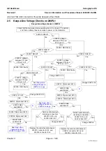
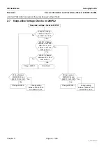
Job Card TSG A020 - Generator Power-Up Sequence Flow Charts
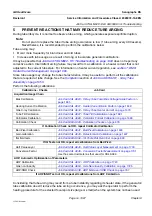
2-3
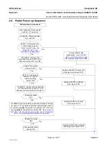
Power-Up Sequence – A
Yes
200PL2 DE1 lit
and
main power contact
K1
not
engaged?
No
200PL1 DE4 lit?
Yes
No
Change 200PL2.
Check the incoming mains voltage
and re-configure the "SEL" wire on
200PL1. See
200PL1 N1 and
N2 lit?
Yes
No
200PL1: Check configuration of the
IN1 voltage selection "STRAP" (see
Job Card PHY A016 - AC Connection
) and check tightness of
TR1 primary lugs.
IN2 configuration
and TR1 primary
lug tightness OK?
Correct IN2 configuration (see
) or
re-tighten TR1 primary lugs.
200PL1 connectors
XJ1 and XJ3 tight?
Re-tighten connectors
XJ1 and/or XJ3.
200PL1: Problem with X1 relay.
On 200PL2, strap PT13 to 0VV and
observe if X1 activates.
200PL1 relay X1
activated?
Change 200PL2.
200PL1: Strap 0VV to anode of D2
and observe whether X1 activates.
200PL1 relay X1
activated?
Replace the cable between 200PL1
connector XJ14 and 200PL2
connector XJ2.
Change X1 relay.
No
Yes
Yes
No
No
No
Yes
Yes
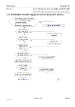
Voltage across coil
terminals of main power
contact K1 OK?
No
Yes
Change main power
contact K1.
Continuity between coil
terminals of main power
contact K1 and 200PL1
XJ10 connector OK?
Change cable bundle
coming from 200PL2 XJ10.
No
On 200PL2, strap PT17 to 0VV
and observe if K1 activates.
Main power contact
K1 activated?
Change 200PL2.
Yes
Yes
No
Cable between
200PL1 XJ14 and
200PL2 XJ2 OK?
No
Yes
Change 200PL1.
Replace the cable between 200PL1
connector XJ14 and 200PL2
connector XJ2.
A


