SECTION 8: Specifications and Safety
2025653-048 Revision B
Responder
™
2000
Page 98
Component Descriptions
Main Board
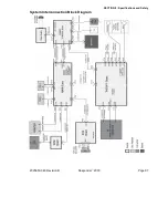
The Main Board controls all major subsystems and user interface.
Controls defibrillation (J210), pacing, ECG (J212), and SpO
2
(J221) functions
Controls the display interface and provides 3.3V (J214) and high voltage backlight power (J213) for LCD.
Controls (J219) and provides 5V (J220) for the Printer
Controls the speaker (J216)
Software upgrade path through the serial port (pass-through from the Power Control Board)
Therapy Board
The
Therapy Board
delivers energy for defibrillation and pacing. It is also a pass-through to the main board for controls,
ID features on defibrillator paddles, and ECG signals. Specifics include:
3 kV electrical isolation to separate the patient from the unit and earth ground
Delivers up to 270J biphasic defibrillator shock (J101, J102, & J109)
Delivers up to 140mA 40ms pace pulses
Charges two 100uF Capacitors to 2 kV (J105 & J107 negative; J104 & J106 positive)
Connects to the Main Board (J110)
Receives power from the Power Control Board (J103)
ECG Board
The optional
ECG Board
receives input from ECG leads connected. The
ECG Board
then amplifies and digitizes the data
and passes it on to the Main Board
4 kV electrical isolation to separate the patient from the unit and earth ground
Connects to the Main board (J412)
ECG Leads connect at J23
Power Control Board
The Power Control Board provides power to the unit (J303, J311), charges the battery (J325), and provides UI pass-
through (J318). Specifics include:
Receives power from the Power Supply (J315)
Provides RS-232 service connection (J317)
Buttons connected to the Power Control board include: Power (on/off), Charge, Shock, Manual shock, and Trim knob
(J324)
LEDs include: AC Power, Shock, Manual, Charge, Power, Fault, Battery Charge
Powers the Fan (J323).
SpO
2
Board
The optional SpO
2
board (P221) mounts to the Main board and patient SpO
2
sensor connection is directly to the SpO
2
module (J11).


