25
Installation Instructions
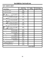
DUCT LENGTH CHART
Duct Fitting
Number
Total Equivalent
Duct Fitting
Equivalent Length
of Fittings
Length of Fitting
8
″
Diameter 90° Elbow
5 ft.
(1.52 m)
6
″
Diameter 45° Elbow
2.5 ft.
(0.76 m)
5
″
to 6
″
Transition
1 ft.
(12.7 cm to 15.24 cm)
(0.30 m)
6
″
to 3
1
⁄
4
″
x 10
″
90° Elbow
5 ft.
(15.24 cm to 8.26 cm x 25.4 cm)
(1.52 m)
3
1
⁄
4
″
x 10
″
to 6
″
90° Elbow
9 ft.
(8.26 cm x 25.4 cm to 15.24 cm)
(2.75 m)
6
″
to 3
1
⁄
4
″
x 10
″
Transition
1 ft.
(15.24 cm to 8.26 cm x 25.4 cm)
(0.30 m)
3
1
⁄
4
″
x 10
″
to 6
″
Transition
4.5 ft.
(8.26 cm x 25.4 cm to 15.24 cm)
(1.37 m)
5
″
to 3
1
⁄
4
″
x 10
″
90° Elbow
6 ft.
(12.7 cm to 8.26 cm x 25.4 cm)
(1.83 m)
3
1
⁄
4
″
x 10
″
90° Elbow
5 ft.
(8.26 cm x 25.4 cm)
(1.52 m)
3
1
⁄
4
″
x 10
″
Flat Elbow
12 ft.
(8.26 cm x 25.4 cm)
(3.66 m)
6
″
Wall Cap
28 ft.
(15.24 cm)
(8.53 m)
3
1
⁄
4
″
x 10
″
Wall Cap
20 ft.
(8.26 cm x 25.4 cm)
(6.10 m)
10
″
x 10
″
Roof Jack
0 ft.
(25.4 cm x 25.4 cm)
(0 m)
Thermal Break
2 ft.
(0.61 m)
6
″
Diameter Straight Duct–Feet
1 ft.
(For flex duct multiply by 2.)
(0.30 m)
3
1
⁄
4
″
x 10
″
Straight Duct–Feet
1 ft.
(0.30 m)
System Total
Air Flow
Air Flow
Air Flow
Air Flow
Air Flow
Air Flow
Air Flow this direction not recommended.
Air Flow this direction not recommended.


