background image

Chapter 3. Application System Architecture 

GFK-2928 

December 2017 


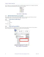
Figure 4: Fault Table Display 

The message provides the slot number (

S08

 in the example) in which the PROFINET Controller is installed, the 

device number (

D004

) for the Bus A GCG, the serial bus address (

SBA02

) for the Genius device, and either Loss 

of Device (

LOD

) or Addition of device (

AOD

). 

3.4


Development Environment 

The software components require Proficy Machine Edition, version 9.5 or later. 

3.5


Simplified Description of Project Upgrade Steps 


Convert the existing Series 90 project into an RX3i project. 


Import Software Components for Dual Bus into the 

Proficy Machine Edition Toolchest


Edit the Primary/Secondary Hardware Configurations. 


Drag the Dual Bus application components from the 

Toolchest


into the project’s PLC Program Blocks.


Add/Edit the Dual Bus Application Blocks: 

o


Add an instance of the ladder block 

BUSSES

 in 

_Main.


o


Enter 

GBusses

 for the name. 

o


Edit 

INIT_GB00

 in 

BUSSES

 to match the configuration of the Genius devices on the first dual 

bus pair. 

o


If there are more dual busses then:  


Copy, then paste the block named 

INIT_GBnn

 in 

BUSSES.


Rename 

INIT_GBnn

 by changing 

nn

 to the next bus number. 


Edit the block contents to accommodate the configuration settings for the PNC, 
GCG, and Genius device reference addresses. 


Add a new instance of the function block 

DBUS.


Name the instance using 

DBnn

 by changing 

nn

 to the next bus number. 


Repeat for the remaining busses, if any. 


Summary of Contents for PACSystems* RX3i

Page 1: ...n Controls For Public Disclosure Programmable Control Products PACSystems RX3i Genius Dual Bus Application Guide Application Guide GFK 2928 PACSystems RX3i Genius Dual Bus Application Guide GFK 2928 D...

Page 2: ...no warranty as to the accuracy of the information included herein Changes modifications and or improvements to equipment and specifications are made periodically and these changes may or may not be re...

Page 3: ...tomation com support Americas Phone 1 800 433 2682 International Americas Direct Dial 1 780 420 2010 if toll free 800 option is unavailable Customer Care Email digitalsupport ge com Primary language o...

Page 4: ...System and Dual Bus References 8 3 3 Dual Bus Mapping Description 8 3 4 Development Environment 9 3 5 Simplified Description of Project Upgrade Steps 9 Chapter 4 Toolchest Components 11 4 1 Add Toolc...

Page 5: ...Built in Ethernet Port of the CPU 24 5 4 Configure the PROFINET Controller Module 25 5 5 Configure the Genius Communication Gateway Modules 26 Settings Tab 26 GENIUS Gateway Parameter Tab 26 Genius D...

Page 6: ...Paste INIT_GBnn Block 17 Figure 14 Rename and Edit INIT_GBnn Block 17 Figure 15 Genus Bus Number Assignment 18 Figure 16 PNC Assignments 18 Figure 17 GCG Assignments Bus A 19 Figure 18 GCG Assignment...

Page 7: ......

Page 8: ...ion solution Operates upon Dual Redundant Hot Standby RX3i PLC platforms Interfaces to existing Genius I O devices by way of PROFINET Controllers and Genius Communications Gateway modules Is scalable...

Page 9: ...Chapter 1 Introduction 2 PACSystems RX3i Genius Dual Bus Application Guide GFK 2928 1 1 Revisions in this Manual Rev Date Description Dec 2017 Initial publication...

Page 10: ...4 PACSystems RX3i PROFIBUS Modules User s Manual GFK 2301 PACSystems RX3i Max On Hot Standby Redundancy User s Manual GFK 2409 PACSystems RX3i Ethernet Network Interface Unit User s Manual GFK 2439 PA...

Page 11: ...Genius Bus Switching Module CPE RX3i CPU with embedded Ethernet GCG Genius Communication Gateway GCG001 HHM Genius Hand Held Monitor MRP Ethernet Media Redundancy Protocol PME Proficy Machine Edition...

Page 12: ...quired In the RX3i environment Genius devices must be interfaced via the Genius Communications Module GCG001 which then communicates over PROFINET with the host PLC GCG001 supports a number of differe...

Page 13: ......

Page 14: ...will require the following items to interface with each dual Genius I O network Four Genius Communications Gateway modules two associated with the Primary PLC interface and two with the Secondary PLC...

Page 15: ...onfigured to have discrete inputs must have one block of references assigned to Bus A and a separate unique block of references assigned to Bus B The application logic is always solved using the refer...

Page 16: ...Machine Edition Toolchest Edit the Primary Secondary Hardware Configurations Drag the Dual Bus application components from the Toolchest into the project s PLC Program Blocks Add Edit the Dual Bus Ap...

Page 17: ......

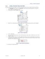
Page 18: ...d on the right side of PME Right click on the Toolchest to display a popup menu that will allow you to import a Toolchest Drawer Double click on the menu item Import Drawer Figure 6 Import Toolchest D...

Page 19: ...items to your project While depressing the Ctrl key drag the following items from the Toolchest s DualBus folders into the PLC target Please make certain that the items are added in the proper order...

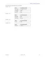
Page 20: ...e as follows Group03 LDs Block Variable Name Entry INIT_GBnn no name required INIT_GB00 IGB00 ALM_DEV DEV EXE_CR CR01 Group04 LDs Block Variable Name Entry DB_SVCS DBS SW_BSM SW01 AUTO_SW Aut_Sw Group...

Page 21: ...s perform the following INIT_GB00 This structured text block defines the parameters for a dual bus the instance is named IGB00 for Initialize Genius Bus 00 The block must be edited to match the specif...

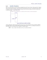
Page 22: ...his block will require editing in order to enter parameters that define the operation and devices on the corresponding dual bus Figure 10 Edit Genius Bus Definition Block s Note the variable on the le...

Page 23: ...instance of the DBUS function block In this case the block refers to the first dual bus The name DB00 relates to the first bus Figure 11 Edit Block for Mapping Each Dual Bus Note the bus variable on t...

Page 24: ...NIT_GBnn Block 3 Right click on Program Blocks in the Navigator pane The following pop up menu will be displayed Figure 13 Paste INIT_GBnn Block 4 Click on Paste Block 5 Because the block already exis...

Page 25: ...st have a unique value that is in the range of 0 to 15 PNC Configuration Figure 16 PNC Assignments BUS PNC_SLOT2 The PNC slot number is used to identify the slot location in which the PROFINET control...

Page 26: ...the Primary PLC Gateway module attached to Bus A BUS GCG_A GSDA The Genius Device Status bits for the Primary PLC Gateway module attached to Bus A Figure 18 GCG Assignments Bus B BUS GCG_B PRI_NUM The...

Page 27: ...on Bus BUS Devices nn DI_Add This parameter applies to devices that contain discrete inputs It is the starting reference assignment for the device installed at Serial Bus Address nn BUS Devices nn DI_...

Page 28: ...outputs must be configured so that the dual mapping routine can post loss of device or addition of device messages Also the device status i e the presence on either Bus A or Bus B is shared between th...

Page 29: ......

Page 30: ...Bulk Memory 65536 Symbolic Discrete 65536 Symbolic Non Discrete 65536 I O Discrete 65536 I O Non Discrete 65536 5 2 Transfer List Entries Input Transfer Points I configured for length 0 Q as needed M...

Page 31: ...the Input Transfer List if you wish to perform automatic role switches based upon the loss of devices on a GCG Figure 21 Include ACTV_CSB in Input Transfer List 5 3 Configure the Built in Ethernet Por...

Page 32: ...OFINET Status Address NOTE 1 For each slot in which a PROFINET Controller is installed the Primary module and the Secondary module will always have identical Status Addresses However the PROFINET Cont...

Page 33: ...ty Genius Device Fault state and GCG Module OK Refer to the PACSystems RX3i Genius Communications Gateway User Manual GFK 2892 Section 5 1 1 Figure 26 GCG Gateway Status Data Reference Assignments NOT...

Page 34: ...e G_Bus Note that the parameters are configured using the function blocks derived from either INIT_GB00 or INIT_GBnn Output PNCST Provides a copy of the status information for the associated PROFINET...

Page 35: ...me View of Genius Devices on Dual Busses Device Status Bits Zoom into the block to observe the current connection status for all configured Genius devices on the dual bus pair Four rungs display the d...

Page 36: ...to Bus A This reference may be turned on by selecting the contact and then right click The reference maintains its state NOTE The function will turn ON its fault output if TO_A and TO_B are both ON or...

Page 37: ...LC and compare them with the Genius combined status bits in the Backup PLC The comparison is performed within the Serial Bus Address range of 01 29 If any bit in the Backup PLC is ON while it s compar...

Page 38: ......

Page 39: ...bers are available on our web site www geautomation com Additional Resources For more information please visit our web site www geautomation com Copyright 2017 General Electric Company All Rights Rese...

Reviews: