


P54A/B/C/E
Appendix B - Settings and Signals
P54xMED-TM-EN-1
B261
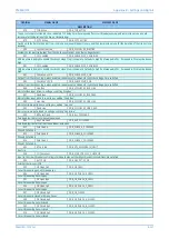
ORDINAL
SIGNAL NAME
ELEMENT NAME
DESCRIPTION
Output DDB can be applied to inhibit reclose by adjacent scheme until local autoreclose scheme confirms it is OK to close CB
1567
1P Reclaim Time
DDB_SP_RECLAIM_TIME
Single Phase AR reclaim time running
1568
1P Reclaim TComp
DDB_SP_RECLAIM_TIME_COMPLETE
Single Phase AR reclaim time complete
1569
3P Reclaim Time
DDB_TP_RECLAIM_TIME
Three Phase AR reclaim time running
1570
3P Reclaim TComp
DDB_TP_RECLAIM_TIME_COMPLETE
Three Phase AR reclaim time complete
1571
CB Succ 1P AR
DDB_CB_SUCCESSFUL_SPAR
This signal is set when CB has successfully completed a single phase autoreclose cycle.
1572
CB Fast SCOK
DDB_CB_FAST_SYSTEM_CHECK_OK
OK to reclose CB with sync check without waiting for dead time to complete
1573
CB SCOK
DDB_CB_LEADER_SYSTEM_CHECK_OK
System conditions OK to reclose CB when dead time complete
1574
CB Man SCOK
DDB_CB_MANUAL_SYSTEM_CHECK_OK
System conditions OK to manually close CB
1575
CB Fail Pr Trip
DDB_CB_FAIL_PROTECTION_TRIP
signal to force CB AR lockout
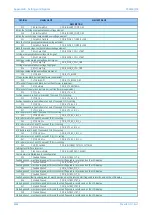
1578
CS1 SlipF>
DDB_CS1_SLIP_O
Line-Bus slip freq > setting [48 93] (frequency difference (slip) between line voltage and bus voltage is greater than maximum slip permitted
for CB synchronism check type 1)
1579
CS1 SlipF<
DDB_CS1_SLIP_U
Line-Bus slip freq < setting [48 93] (frequency difference (slip) between line voltage and bus voltage is greater than maximum slip permitted
for CB synchronism check type 1)
1580
CS VLine<
DDB_SYSCHECKS_VLINE_U
Line Volts < setting [48 8B]
1581
CS VLine>
DDB_SYSCHECKS_VLINE_O
Line Volts > setting [48 8C]
1582
CS VBus<
DDB_SYSCHECKS_VBUS_U
Bus Volts < setting [48 8B]
1583
CS VBus>
DDB_SYSCHECKS_VBUS_O
Bus Volts > setting [48 8C]
1586
CS1 VL>VB
DDB_SYSCHECKS_VLINE_DIFF_HIGH
Voltage magnitude difference between Line V and Bus V is greater than setting [48 91] (line V > Bus V)
1587
CS2 VL>VB
DDB_SYSCHECKS1_2_VLINE_DIFF_HIGH
Voltage magnitude difference between Line V and Bus V is greater than setting [48 96] (line V > Bus V)
1588
CS1 VL<VB
DDB_SYSCHECKS_VBUS_DIFF_HIGH
Voltage magnitude difference between Line V and Bus V is greater than setting [48 91] (line V < Bus V)
1589
CS2 VL<VB
DDB_SYSCHECKS1_2_VBUS_DIFF_HIGH
Voltage magnitude difference between Line V and Bus V is greater than setting [48 96] (line V < Bus V)
1590
CS1 FL>FB
DDB_CS1_LINE_FREQ_GT_BUS_FREQ
Frequency difference between Line V and Bus V is greater than setting [48 93] (line freq > Bus freq)
1591
CS1 FL<FB
DDB_CS1_LINE_FREQ_LT_BUS_FREQ
Frequency difference between Line V and Bus V is greater than setting [48 93] (line freq < Bus freq)
1592
CS1
DDB_CS1_ANGLE_NOT_OK_POS
Line/Bus phase angle in range: setting [48 90] to +180deg (anticlockwise from Vbus)
1593
CS1 AngHigh-
DDB_CS1_ANGLE_NOT_OK_NEG
Line/Bus phase angle in range: setting [48 90] to -180deg (anticlockwise from Vbus)
1594
CS AngRotACW
DDB_SYSCHECKS_ANGLE_ACW
Line freq > (Bus freq + 0.001Hz) (Line voltage vector rotating anticlockwise relative to VBus1)
1595
CS AngRotCW
DDB_SYSCHECKS_ANGLE_CW
Bus freq > (Line freq + 0.001Hz) (Line voltage vector rotating clockwise relative to VBus1)
1609
AR Enable CB
DDB_AR_ENABLE_CB1
External input via DDB to enable CB, if "in service", to be initiated for autoreclosing by an AR initiation signal from protection. DDB input
defaults to high if not mapped in PSL, so CB AR initiation is permitted.
1616
PSL Int 101
DDB_PSLINT_101
PSL Internal Node
Summary of Contents for P4A
Page 2: ......
Page 20: ...Contents P54A B C E xviii P54xMED TM EN 1 ...
Page 27: ...CHAPTER 1 INTRODUCTION ...
Page 28: ...Chapter 1 Introduction P54A B C E 2 P54xMED TM EN 1 ...
Page 38: ...Chapter 1 Introduction P54A B C E 12 P54xMED TM EN 1 ...
Page 39: ...CHAPTER 2 SAFETY INFORMATION ...
Page 40: ...Chapter 2 Safety Information P54A B C E 14 P54xMED TM EN 1 ...
Page 52: ...Chapter 2 Safety Information P54A B C E 26 P54xMED TM EN 1 ...
Page 53: ...CHAPTER 3 HARDWARE DESIGN ...
Page 54: ...Chapter 3 Hardware Design P54A B C E 28 P54xMED TM EN 1 ...
Page 86: ...Chapter 3 Hardware Design P54A B C E 60 P54xMED TM EN 1 ...
Page 87: ...CHAPTER 4 SOFTWARE DESIGN ...
Page 88: ...Chapter 4 Software Design P54A B C E 62 P54xMED TM EN 1 ...
Page 99: ...CHAPTER 5 CONFIGURATION ...
Page 100: ...Chapter 5 Configuration P54A B C E 74 P54xMED TM EN 1 ...
Page 120: ...Chapter 5 Configuration P54A B C E 94 P54xMED TM EN 1 ...
Page 121: ...CHAPTER 6 CURRENT DIFFERENTIAL PROTECTION ...
Page 122: ...Chapter 6 Current Differential Protection P54A B C E 96 P54xMED TM EN 1 ...
Page 149: ...CHAPTER 7 AUTORECLOSE ...
Page 150: ...Chapter 7 Autoreclose P54A B C E 124 P54xMED TM EN 1 ...
Page 207: ...CHAPTER 8 CB FAIL PROTECTION ...
Page 208: ...Chapter 8 CB Fail Protection P54A B C E 182 P54xMED TM EN 1 ...
Page 219: ...CHAPTER 9 CURRENT PROTECTION FUNCTIONS ...
Page 220: ...Chapter 9 Current Protection Functions P54A B C E 194 P54xMED TM EN 1 ...
Page 244: ...Chapter 9 Current Protection Functions P54A B C E 218 P54xMED TM EN 1 ...
Page 247: ...CHAPTER 10 VOLTAGE PROTECTION FUNCTIONS ...
Page 248: ...Chapter 10 Voltage Protection Functions P54A B C E 222 P54xMED TM EN 1 ...
Page 261: ...CHAPTER 11 FREQUENCY PROTECTION FUNCTIONS ...
Page 262: ...Chapter 11 Frequency Protection Functions P54A B C E 236 P54xMED TM EN 1 ...
Page 268: ...Chapter 11 Frequency Protection Functions P54A B C E 242 P54xMED TM EN 1 ...
Page 269: ...CHAPTER 12 MONITORING AND CONTROL ...
Page 270: ...Chapter 12 Monitoring and Control P54A B C E 244 P54xMED TM EN 1 ...
Page 300: ...Chapter 12 Monitoring and Control P54A B C E 274 P54xMED TM EN 1 ...
Page 301: ...CHAPTER 13 SUPERVISION ...
Page 302: ...Chapter 13 Supervision P54A B C E 276 P54xMED TM EN 1 ...
Page 312: ...Chapter 13 Supervision P54A B C E 286 P54xMED TM EN 1 ...
Page 323: ...CHAPTER 14 DIGITAL I O AND PSL CONFIGURATION ...
Page 324: ...Chapter 14 Digital I O and PSL Configuration P54A B C E 298 P54xMED TM EN 1 ...
Page 336: ...Chapter 14 Digital I O and PSL Configuration P54A B C E 310 P54xMED TM EN 1 ...
Page 337: ...CHAPTER 15 FIBRE TELEPROTECTION ...
Page 338: ...Chapter 15 Fibre Teleprotection P54A B C E 312 P54xMED TM EN 1 ...
Page 354: ...Chapter 15 Fibre Teleprotection P54A B C E 328 P54xMED TM EN 1 ...
Page 355: ...CHAPTER 16 ELECTRICAL TELEPROTECTION ...
Page 356: ...Chapter 16 Electrical Teleprotection P54A B C E 330 P54xMED TM EN 1 ...
Page 366: ...Chapter 16 Electrical Teleprotection P54A B C E 340 P54xMED TM EN 1 ...
Page 367: ...CHAPTER 17 COMMUNICATIONS ...
Page 368: ...Chapter 17 Communications P54A B C E 342 P54xMED TM EN 1 ...
Page 439: ...CHAPTER 18 CYBER SECURITY ...
Page 440: ...Chapter 18 Cyber Security P54A B C E 414 P54xMED TM EN 1 ...
Page 457: ...CHAPTER 19 INSTALLATION ...
Page 458: ...Chapter 19 Installation P54A B C E 432 P54xMED TM EN 1 ...
Page 471: ...CHAPTER 20 COMMISSIONING INSTRUCTIONS ...
Page 472: ...Chapter 20 Commissioning Instructions P54A B C E 446 P54xMED TM EN 1 ...
Page 513: ...CHAPTER 21 MAINTENANCE AND TROUBLESHOOTING ...
Page 514: ...Chapter 21 Maintenance and Troubleshooting P54A B C E 488 P54xMED TM EN 1 ...
Page 530: ...Chapter 21 Maintenance and Troubleshooting P54A B C E 504 P54xMED TM EN 1 ...
Page 531: ...CHAPTER 22 TECHNICAL SPECIFICATIONS ...
Page 532: ...Chapter 22 Technical Specifications P54A B C E 506 P54xMED TM EN 1 ...
Page 558: ...Chapter 22 Technical Specifications P54A B C E 532 P54xMED TM EN 1 ...
Page 559: ...APPENDIX A ORDERING OPTIONS ...
Page 560: ...Appendix A Ordering Options P54A B C E P54xMED TM EN 1 ...
Page 565: ...APPENDIX B SETTINGS AND SIGNALS ...
Page 566: ...Appendix B Settings and Signals P54A B C E P54xMED TM EN 1 ...
Page 790: ...Appendix B Settings and Signals P54A B C E B224 P54xMED TM EN 1 ...
Page 835: ...APPENDIX C WIRING DIAGRAMS ...
Page 836: ...Appendix C Wiring Diagrams P54A B C E P54xMED TM EN 1 ...
Page 849: ......