


P54A/B/C/E
Appendix B - Settings and Signals
P54xMED-TM-EN-1
B259
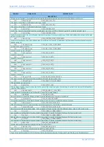
ORDINAL
SIGNAL NAME
ELEMENT NAME
DESCRIPTION
1381
Group Alarm
DDB_GROUP_ALARM
This is an output signal available in the PSL, which can be mapped in IEC870-5-103 to a major problem normally linked to the watchdog
1382
AR On Pulse
DDB_AR_ON_PULSE
This is an output signal available in the PSL, which can be mapped to enable AR via pulse
1383
AR Off Pulse
DDB_AR_OFF_PULSE
This is an output signal available in the PSL, which can be mapped to disable AR via pulse
1384
AR Enable
DDB_AR_ENABLE
External input via DDB mapped in PSL to enable AR if Enable AR CB1 or Enable AR CB2 is set and AR Configuration setting is enabled
1385
AR In Service
DDB_AR_IN_SERVICE
Auto-reclose in service
1386
MaxCh1 PropDelay
DDB_MAX_CH1_PROP_DELAY
Setting MaxCh 1 PropDelay has been exceeded
1387
MaxCh2 PropDelay
DDB_MAX_CH2_PROP_DELAY
Setting MaxCh 2 PropDelay has been exceeded
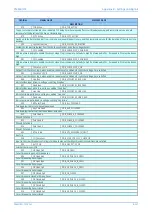
1420
Inhibit AR
DDB_INHIBIT_AR
DDB mapped in PSL from opto or comms input. External signal to inhibit autoreclose.
1464
CS2 SlipF>
DDB_CS2_SLIP_O
Line-Bus 1 slip freq > setting [48 98] (frequency difference (slip) between line voltage and bus 1 voltage is greater than maximum slip
permitted for CB synchronism check stage 2)
1465
CS2 SlipF<
DDB_CS2_SLIP_U
Line-Bus 1 slip freq < setting [48 98] (frequency difference (slip) between line voltage and bus voltage is within the permitted range for CB
synchronism check stage 2)
1493
CS2 FL>FB
DDB_CS2_LINE_FREQ_GT_BUS_FREQ
Frequency difference between Line V and Bus1 V is greater than setting [48 98] (line freq > Bus freq)
1494
CS2 FL<FB
DDB_CS2_LINE_FREQ_LT_BUS_FREQ
Frequency difference between Line V and Bus1 V is greater than setting [48 98] (line freq < Bus freq)
1495
CS2
DDB_CS2_ANGLE_NOT_OK_POS
Line/Bus1 phase angle in range: setting [48 95] to +180deg (anticlockwise from Vbus)
1496
CS2 AngHigh-
DDB_CS2_ANGLE_NOT_OK_NEG
Line/Bus1 phase angle in range: setting [48 95] to -180deg (clockwise from Vbus)
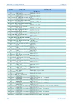
1497
AR Mode 1P
DDB_LEAD_AR_SP
If setting "Lead AR Mode" = Opto, then if input DDB "AR Mode 1P" is high, the leader CB is enabled for single phase autoreclose, if "AR Mode
1P" is low, the leader CB is NOT enabled for single phase autoreclose.
1498
AR Mode 3P
DDB_LEAD_AR_3P
If setting "Lead AR Mode" = Opto, then if input DDB "AR Mode 3P" is high, the leader CB is enabled for three phase autoreclose, if "AR Mode 3P"
is low, the leader CB is NOT enabled for three phase autoreclose.
1504
Init APh AR Test
DDB_INIT_APH_AR_TEST
DDB mapped in PSL from opto or comms input. Input operation will initiate APh test trip & autoreclose cycle
1505
Init BPh AR Test
DDB_INIT_BPH_AR_TEST
DDB mapped in PSL from opto or comms input. Input operation will initiate BPh test trip & autoreclose cycle
1506
Init CPh AR Test
DDB_INIT_CPH_AR_TEST
DDB mapped in PSL from opto or comms input. Input operation will initiate CPh test trip & autoreclose cycle
1507
Init 3P AR Test
DDB_INIT_3PH_AR_TEST
DDB mapped in PSL from opto or comms input. Input operation will initiate 3Ph test trip & autoreclose cycle
1508
Ext Fault APh
DDB_EXTERNAL_FAULT_A
DDB mapped in PSL from opto or comms input: indicates external protection operated for fault involving A phase
1509
Ext Fault BPh
DDB_EXTERNAL_FAULT_B
DDB mapped in PSL from opto or comms input: indicates external protection operated for fault involving C phase
1510
Ext Fault CPh
DDB_EXTERNAL_FAULT_C
DDB mapped in PSL from opto or comms input: indicates external protection operated for fault involving C phase
1511
AR Skip Shot1
DDB_AR_SKIP_SHOT1
DDB mapped in PSL from opto or comms input: if setting "AR Skip Shot 1" = Enable and this input is high when a protection operation initiates
an autoreclose cycle, then the sequence counter advances directly to SC:COUNT = 2 so the autoreclose cycle skips
1517
Ext Rst AROK
DDB_EXTERNAL_RES_CB_AROK
DDB mapped in PSL from opto or comms input. This input DDB is used when required to reset any CB "Successful Autoreclose" signal.
1518
Ext Rst CB Shots
DDB_EXTERNAL_RES_CB_SHOTS
DDB mapped in PSL from opto or comms input. This input DDB is used when required to reset the CB cumulative "Shots" counters.
1521
MCB/VTS CB CS
DDB_MCB_VTS_CS1
Summary of Contents for P4A
Page 2: ......
Page 20: ...Contents P54A B C E xviii P54xMED TM EN 1 ...
Page 27: ...CHAPTER 1 INTRODUCTION ...
Page 28: ...Chapter 1 Introduction P54A B C E 2 P54xMED TM EN 1 ...
Page 38: ...Chapter 1 Introduction P54A B C E 12 P54xMED TM EN 1 ...
Page 39: ...CHAPTER 2 SAFETY INFORMATION ...
Page 40: ...Chapter 2 Safety Information P54A B C E 14 P54xMED TM EN 1 ...
Page 52: ...Chapter 2 Safety Information P54A B C E 26 P54xMED TM EN 1 ...
Page 53: ...CHAPTER 3 HARDWARE DESIGN ...
Page 54: ...Chapter 3 Hardware Design P54A B C E 28 P54xMED TM EN 1 ...
Page 86: ...Chapter 3 Hardware Design P54A B C E 60 P54xMED TM EN 1 ...
Page 87: ...CHAPTER 4 SOFTWARE DESIGN ...
Page 88: ...Chapter 4 Software Design P54A B C E 62 P54xMED TM EN 1 ...
Page 99: ...CHAPTER 5 CONFIGURATION ...
Page 100: ...Chapter 5 Configuration P54A B C E 74 P54xMED TM EN 1 ...
Page 120: ...Chapter 5 Configuration P54A B C E 94 P54xMED TM EN 1 ...
Page 121: ...CHAPTER 6 CURRENT DIFFERENTIAL PROTECTION ...
Page 122: ...Chapter 6 Current Differential Protection P54A B C E 96 P54xMED TM EN 1 ...
Page 149: ...CHAPTER 7 AUTORECLOSE ...
Page 150: ...Chapter 7 Autoreclose P54A B C E 124 P54xMED TM EN 1 ...
Page 207: ...CHAPTER 8 CB FAIL PROTECTION ...
Page 208: ...Chapter 8 CB Fail Protection P54A B C E 182 P54xMED TM EN 1 ...
Page 219: ...CHAPTER 9 CURRENT PROTECTION FUNCTIONS ...
Page 220: ...Chapter 9 Current Protection Functions P54A B C E 194 P54xMED TM EN 1 ...
Page 244: ...Chapter 9 Current Protection Functions P54A B C E 218 P54xMED TM EN 1 ...
Page 247: ...CHAPTER 10 VOLTAGE PROTECTION FUNCTIONS ...
Page 248: ...Chapter 10 Voltage Protection Functions P54A B C E 222 P54xMED TM EN 1 ...
Page 261: ...CHAPTER 11 FREQUENCY PROTECTION FUNCTIONS ...
Page 262: ...Chapter 11 Frequency Protection Functions P54A B C E 236 P54xMED TM EN 1 ...
Page 268: ...Chapter 11 Frequency Protection Functions P54A B C E 242 P54xMED TM EN 1 ...
Page 269: ...CHAPTER 12 MONITORING AND CONTROL ...
Page 270: ...Chapter 12 Monitoring and Control P54A B C E 244 P54xMED TM EN 1 ...
Page 300: ...Chapter 12 Monitoring and Control P54A B C E 274 P54xMED TM EN 1 ...
Page 301: ...CHAPTER 13 SUPERVISION ...
Page 302: ...Chapter 13 Supervision P54A B C E 276 P54xMED TM EN 1 ...
Page 312: ...Chapter 13 Supervision P54A B C E 286 P54xMED TM EN 1 ...
Page 323: ...CHAPTER 14 DIGITAL I O AND PSL CONFIGURATION ...
Page 324: ...Chapter 14 Digital I O and PSL Configuration P54A B C E 298 P54xMED TM EN 1 ...
Page 336: ...Chapter 14 Digital I O and PSL Configuration P54A B C E 310 P54xMED TM EN 1 ...
Page 337: ...CHAPTER 15 FIBRE TELEPROTECTION ...
Page 338: ...Chapter 15 Fibre Teleprotection P54A B C E 312 P54xMED TM EN 1 ...
Page 354: ...Chapter 15 Fibre Teleprotection P54A B C E 328 P54xMED TM EN 1 ...
Page 355: ...CHAPTER 16 ELECTRICAL TELEPROTECTION ...
Page 356: ...Chapter 16 Electrical Teleprotection P54A B C E 330 P54xMED TM EN 1 ...
Page 366: ...Chapter 16 Electrical Teleprotection P54A B C E 340 P54xMED TM EN 1 ...
Page 367: ...CHAPTER 17 COMMUNICATIONS ...
Page 368: ...Chapter 17 Communications P54A B C E 342 P54xMED TM EN 1 ...
Page 439: ...CHAPTER 18 CYBER SECURITY ...
Page 440: ...Chapter 18 Cyber Security P54A B C E 414 P54xMED TM EN 1 ...
Page 457: ...CHAPTER 19 INSTALLATION ...
Page 458: ...Chapter 19 Installation P54A B C E 432 P54xMED TM EN 1 ...
Page 471: ...CHAPTER 20 COMMISSIONING INSTRUCTIONS ...
Page 472: ...Chapter 20 Commissioning Instructions P54A B C E 446 P54xMED TM EN 1 ...
Page 513: ...CHAPTER 21 MAINTENANCE AND TROUBLESHOOTING ...
Page 514: ...Chapter 21 Maintenance and Troubleshooting P54A B C E 488 P54xMED TM EN 1 ...
Page 530: ...Chapter 21 Maintenance and Troubleshooting P54A B C E 504 P54xMED TM EN 1 ...
Page 531: ...CHAPTER 22 TECHNICAL SPECIFICATIONS ...
Page 532: ...Chapter 22 Technical Specifications P54A B C E 506 P54xMED TM EN 1 ...
Page 558: ...Chapter 22 Technical Specifications P54A B C E 532 P54xMED TM EN 1 ...
Page 559: ...APPENDIX A ORDERING OPTIONS ...
Page 560: ...Appendix A Ordering Options P54A B C E P54xMED TM EN 1 ...
Page 565: ...APPENDIX B SETTINGS AND SIGNALS ...
Page 566: ...Appendix B Settings and Signals P54A B C E P54xMED TM EN 1 ...
Page 790: ...Appendix B Settings and Signals P54A B C E B224 P54xMED TM EN 1 ...
Page 835: ...APPENDIX C WIRING DIAGRAMS ...
Page 836: ...Appendix C Wiring Diagrams P54A B C E P54xMED TM EN 1 ...
Page 849: ......