
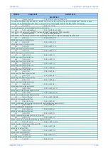


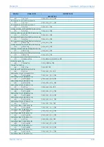
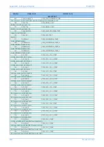

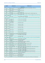


Appendix B - Settings and Signals
P54A/B/C/E
B252
P54xMED-TM-EN-1
ORDINAL
SIGNAL NAME
ELEMENT NAME
DESCRIPTION
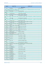
1105
Function Key 10
DDB_FN_KEY_10
Function key 10 is activated. In ‘Normal’ mode it is high on keypress and in ‘Toggle’ mode remains high/low on single keypress
1024
LED 1
DDB_OUTPUT_LED_1
Programmable LED 1
1025
LED 2
DDB_OUTPUT_LED_2
Programmable LED 2
1026
LED 3
DDB_OUTPUT_LED_3
Programmable LED 3
1027
LED 4
DDB_OUTPUT_LED_4
Programmable LED 4
1028
LED 5
DDB_OUTPUT_LED_5
Programmable LED 5
1029
LED 6
DDB_OUTPUT_LED_6
Programmable LED 6
1030
LED 7
DDB_OUTPUT_LED_7
Programmable LED 7
1031
LED 8
DDB_OUTPUT_LED_8
Programmable LED 8
1070
LED Cond IN 1
DDB_LED_CON_1
Input to LED Output Condition
1071
LED Cond IN 2
DDB_LED_CON_2
Input to LED Output Condition
1072
LED Cond IN 3
DDB_LED_CON_3
Input to LED Output Condition
1073
LED Cond IN 4
DDB_LED_CON_4
Input to LED Output Condition
1074
LED Cond IN 5
DDB_LED_CON_5
Input to LED Output Condition
1075
LED Cond IN 6
DDB_LED_CON_6
Input to LED Output Condition
1076
LED Cond IN 7
DDB_LED_CON_7
Input to LED Output Condition
1077
LED Cond IN 8
DDB_LED_CON_8
Input to LED Output Condition
1106
CB I^ Maint
DDB_BROKEN_CURRENT_ALARM
Broken current maintenance alarm - circuit breaker cumulative duty alarm set-point
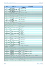
1107
CB I^ Lockout
DDB_BROKEN_CURRENT_LOCKOUT
Broken current lockout alarm - circuit breaker cumulative duty has been exceeded
1108
No.CB OPs Maint
DDB_MAINTENANCE_ALARM
No of circuit breaker operations maintenance alarm - indicated due to circuit breaker trip operations threshold
1109
No.CB OPs Lock
DDB_MAINTENANCE_LOCKOUT
No of circuit breaker operations maintenance lockout - excessive number of circuit breaker trip operations, safety lockout
1110
CB Time Maint
DDB_EXCESSIVE_OP_TIME_ALARM
Excessive circuit breaker operating time maintenance alarm - excessive operation time alarm for the circuit breaker (slow interruption time)
1111
CB Time Lockout
DDB_EXCESSIVE_OP_TIME_LOCKOUT
Excessive circuit breaker operating time lockout alarm - excessive operation time alarm for the circuit breaker (too slow interruption)
1112
CB FaultFreqLock
DDB_EFF_LOCKOUT
Excessive fault frequency lockout alarm
1120
SignalFail Ch1Rx
DDB_SIGNALLING_FAIL_CH1_RX
Reception of messages on channel 1 has stopped
1121
SignalFail Ch1Tx
DDB_SIGNALLING_FAIL_CH1_TX
Transmission of messages on channel 1 has stopped
1124
Ch1 Signal Lost
DDB_IEEE37_94_CH1_LOSS_OF_SIG
Mux indicates signal lost over channel 1
1125
Ch1 Path Yellow
DDB_IEEE37_94_CH1_PATH_YELLOW
One way communication. Local relay that is sending over Ch1 indicates that remote end is not receiving
1130
SignalFail Ch2Rx
DDB_SIGNALLING_FAIL_CH2_RX
Reception of messages on channel 2 has stopped
Summary of Contents for P4A
Page 2: ......
Page 20: ...Contents P54A B C E xviii P54xMED TM EN 1 ...
Page 27: ...CHAPTER 1 INTRODUCTION ...
Page 28: ...Chapter 1 Introduction P54A B C E 2 P54xMED TM EN 1 ...
Page 38: ...Chapter 1 Introduction P54A B C E 12 P54xMED TM EN 1 ...
Page 39: ...CHAPTER 2 SAFETY INFORMATION ...
Page 40: ...Chapter 2 Safety Information P54A B C E 14 P54xMED TM EN 1 ...
Page 52: ...Chapter 2 Safety Information P54A B C E 26 P54xMED TM EN 1 ...
Page 53: ...CHAPTER 3 HARDWARE DESIGN ...
Page 54: ...Chapter 3 Hardware Design P54A B C E 28 P54xMED TM EN 1 ...
Page 86: ...Chapter 3 Hardware Design P54A B C E 60 P54xMED TM EN 1 ...
Page 87: ...CHAPTER 4 SOFTWARE DESIGN ...
Page 88: ...Chapter 4 Software Design P54A B C E 62 P54xMED TM EN 1 ...
Page 99: ...CHAPTER 5 CONFIGURATION ...
Page 100: ...Chapter 5 Configuration P54A B C E 74 P54xMED TM EN 1 ...
Page 120: ...Chapter 5 Configuration P54A B C E 94 P54xMED TM EN 1 ...
Page 121: ...CHAPTER 6 CURRENT DIFFERENTIAL PROTECTION ...
Page 122: ...Chapter 6 Current Differential Protection P54A B C E 96 P54xMED TM EN 1 ...
Page 149: ...CHAPTER 7 AUTORECLOSE ...
Page 150: ...Chapter 7 Autoreclose P54A B C E 124 P54xMED TM EN 1 ...
Page 207: ...CHAPTER 8 CB FAIL PROTECTION ...
Page 208: ...Chapter 8 CB Fail Protection P54A B C E 182 P54xMED TM EN 1 ...
Page 219: ...CHAPTER 9 CURRENT PROTECTION FUNCTIONS ...
Page 220: ...Chapter 9 Current Protection Functions P54A B C E 194 P54xMED TM EN 1 ...
Page 244: ...Chapter 9 Current Protection Functions P54A B C E 218 P54xMED TM EN 1 ...
Page 247: ...CHAPTER 10 VOLTAGE PROTECTION FUNCTIONS ...
Page 248: ...Chapter 10 Voltage Protection Functions P54A B C E 222 P54xMED TM EN 1 ...
Page 261: ...CHAPTER 11 FREQUENCY PROTECTION FUNCTIONS ...
Page 262: ...Chapter 11 Frequency Protection Functions P54A B C E 236 P54xMED TM EN 1 ...
Page 268: ...Chapter 11 Frequency Protection Functions P54A B C E 242 P54xMED TM EN 1 ...
Page 269: ...CHAPTER 12 MONITORING AND CONTROL ...
Page 270: ...Chapter 12 Monitoring and Control P54A B C E 244 P54xMED TM EN 1 ...
Page 300: ...Chapter 12 Monitoring and Control P54A B C E 274 P54xMED TM EN 1 ...
Page 301: ...CHAPTER 13 SUPERVISION ...
Page 302: ...Chapter 13 Supervision P54A B C E 276 P54xMED TM EN 1 ...
Page 312: ...Chapter 13 Supervision P54A B C E 286 P54xMED TM EN 1 ...
Page 323: ...CHAPTER 14 DIGITAL I O AND PSL CONFIGURATION ...
Page 324: ...Chapter 14 Digital I O and PSL Configuration P54A B C E 298 P54xMED TM EN 1 ...
Page 336: ...Chapter 14 Digital I O and PSL Configuration P54A B C E 310 P54xMED TM EN 1 ...
Page 337: ...CHAPTER 15 FIBRE TELEPROTECTION ...
Page 338: ...Chapter 15 Fibre Teleprotection P54A B C E 312 P54xMED TM EN 1 ...
Page 354: ...Chapter 15 Fibre Teleprotection P54A B C E 328 P54xMED TM EN 1 ...
Page 355: ...CHAPTER 16 ELECTRICAL TELEPROTECTION ...
Page 356: ...Chapter 16 Electrical Teleprotection P54A B C E 330 P54xMED TM EN 1 ...
Page 366: ...Chapter 16 Electrical Teleprotection P54A B C E 340 P54xMED TM EN 1 ...
Page 367: ...CHAPTER 17 COMMUNICATIONS ...
Page 368: ...Chapter 17 Communications P54A B C E 342 P54xMED TM EN 1 ...
Page 439: ...CHAPTER 18 CYBER SECURITY ...
Page 440: ...Chapter 18 Cyber Security P54A B C E 414 P54xMED TM EN 1 ...
Page 457: ...CHAPTER 19 INSTALLATION ...
Page 458: ...Chapter 19 Installation P54A B C E 432 P54xMED TM EN 1 ...
Page 471: ...CHAPTER 20 COMMISSIONING INSTRUCTIONS ...
Page 472: ...Chapter 20 Commissioning Instructions P54A B C E 446 P54xMED TM EN 1 ...
Page 513: ...CHAPTER 21 MAINTENANCE AND TROUBLESHOOTING ...
Page 514: ...Chapter 21 Maintenance and Troubleshooting P54A B C E 488 P54xMED TM EN 1 ...
Page 530: ...Chapter 21 Maintenance and Troubleshooting P54A B C E 504 P54xMED TM EN 1 ...
Page 531: ...CHAPTER 22 TECHNICAL SPECIFICATIONS ...
Page 532: ...Chapter 22 Technical Specifications P54A B C E 506 P54xMED TM EN 1 ...
Page 558: ...Chapter 22 Technical Specifications P54A B C E 532 P54xMED TM EN 1 ...
Page 559: ...APPENDIX A ORDERING OPTIONS ...
Page 560: ...Appendix A Ordering Options P54A B C E P54xMED TM EN 1 ...
Page 565: ...APPENDIX B SETTINGS AND SIGNALS ...
Page 566: ...Appendix B Settings and Signals P54A B C E P54xMED TM EN 1 ...
Page 790: ...Appendix B Settings and Signals P54A B C E B224 P54xMED TM EN 1 ...
Page 835: ...APPENDIX C WIRING DIAGRAMS ...
Page 836: ...Appendix C Wiring Diagrams P54A B C E P54xMED TM EN 1 ...
Page 849: ......