


P54A/B/C/E
Appendix B - Settings and Signals
P54xMED-TM-EN-1
B239
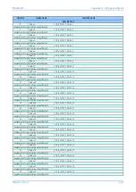
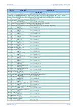
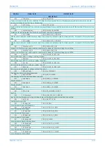
ORDINAL
SIGNAL NAME
ELEMENT NAME
DESCRIPTION
456
Recon Interlock
DDB_RECONFIGURATION_INTERLOCK
This must be energized (along with DDB 455 - inhibit C Diff) at the time that a relay configuration is changed from 3 ended to 2 ended
scheme. This usually should be driven from a 52-B contact of the CB connected to the line end that is taken out of service
459
Test Mode
DDB_TEST_MODE
Commissioning tests - automatically places relay in test mode
460
103 CommandBlock
DDB_COMMAND_BLOCKING
For IEC-870-5-103 protocol only, used for "Command Blocking" (relay ignores SCADA commands)
461
103 MonitorBlock
DDB_MONITOR_BLOCKING
For IEC-870-5-103 protocol only, used for "Monitor Blocking" (relay is quiet - issues no messages via SCADA port)
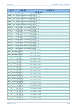
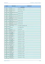
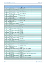
463
Inhibit I>1
DDB_INHIBIT_POC1
Inhibit stage 1 overcurrent protection
464
Inhibit I>2
DDB_INHIBIT_POC2
Inhibit stage 2 overcurrent protection
465
Inhibit I>3
DDB_INHIBIT_POC3
Inhibit stage 3 overcurrent protection
466
Inhibit I>4
DDB_INHIBIT_POC4
Inhibit stage 4 overcurrent protection
467
Inhibit IN>1
DDB_INHIBIT_EF1
Inhibit stage 1 earth fault protection
468
Inhibit IN>2
DDB_INHIBIT_EF2
Inhibit stage 2 earth fault protection
469
Inhibit IN>3
DDB_INHIBIT_EF3
Inhibit stage 3 earth fault protection
470
Inhibit IN>4
DDB_INHIBIT_EF4
Inhibit stage 4 earth fault protection
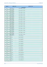
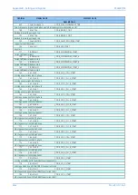
471
Inhibit V<1
DDB_INHIBIT_UV1
Inhibit stage 1 undervoltage protection
472
Inhibit V<2
DDB_INHIBIT_UV2
Inhibit stage 2 undervoltage protection
473
Inhibit V>1
DDB_INHIBIT_OV1
Inhibit stage 1 overvoltage protection
474
Inhibit V>2
DDB_INHIBIT_OV2
Inhibit stage 2 overvoltage protection
475
Inhibit VN>1
DDB_INHIBIT_RESOV1
Inhibit stage 1 residual overvoltage protection
476
Inhibit VN>2
DDB_INHIBIT_RESOV2
Inhibit stage 2 residual overvoltage protection
478
Inhibit Thermal
DDB_INHIBIT_THERMAL
Inhibit thermal overload protection
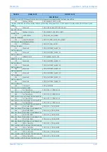
479
InhibitCB Status
DDB_INHIBIT_CBS
Inhibit circuit breaker state monitoring (no alarm for defective/stuck auxiliary contact)
480
Inhibit CB Fail
DDB_INHIBIT_CBF
Inhibit circuit breaker fail protection
481
Inh Broken Line
DDB_INHIBIT_BCL
Inhibit Broken conductor protection
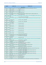
482
Inhibit VTS
DDB_INHIBIT_VTS
Inhibit VT supervision (including turn OF MCB’s) via PSL
483
Inhibit CTS
DDB_INHIBIT_CTS
Inhibit CT supervision (both differential and standard CTS) via PSL
484
InhibitChecksync
DDB_INHIBIT_CHKSYN
Inhibit checksync. (Both stages and for each CB)
485
Inhibit TOR
DDB_INHIBIT_TOR
Inhibit trip on reclose (TOR)
486
Inhibit SOTF
DDB_INHIBIT_SOTF
Inhibit switch onto fault (SOTF)
487
Disable CTS
DDB_DISABLE_CTS
To disable differential CTS via PSL
488
Set SOTF
DDB_SET_SOTF
Summary of Contents for P4A
Page 2: ......
Page 20: ...Contents P54A B C E xviii P54xMED TM EN 1 ...
Page 27: ...CHAPTER 1 INTRODUCTION ...
Page 28: ...Chapter 1 Introduction P54A B C E 2 P54xMED TM EN 1 ...
Page 38: ...Chapter 1 Introduction P54A B C E 12 P54xMED TM EN 1 ...
Page 39: ...CHAPTER 2 SAFETY INFORMATION ...
Page 40: ...Chapter 2 Safety Information P54A B C E 14 P54xMED TM EN 1 ...
Page 52: ...Chapter 2 Safety Information P54A B C E 26 P54xMED TM EN 1 ...
Page 53: ...CHAPTER 3 HARDWARE DESIGN ...
Page 54: ...Chapter 3 Hardware Design P54A B C E 28 P54xMED TM EN 1 ...
Page 86: ...Chapter 3 Hardware Design P54A B C E 60 P54xMED TM EN 1 ...
Page 87: ...CHAPTER 4 SOFTWARE DESIGN ...
Page 88: ...Chapter 4 Software Design P54A B C E 62 P54xMED TM EN 1 ...
Page 99: ...CHAPTER 5 CONFIGURATION ...
Page 100: ...Chapter 5 Configuration P54A B C E 74 P54xMED TM EN 1 ...
Page 120: ...Chapter 5 Configuration P54A B C E 94 P54xMED TM EN 1 ...
Page 121: ...CHAPTER 6 CURRENT DIFFERENTIAL PROTECTION ...
Page 122: ...Chapter 6 Current Differential Protection P54A B C E 96 P54xMED TM EN 1 ...
Page 149: ...CHAPTER 7 AUTORECLOSE ...
Page 150: ...Chapter 7 Autoreclose P54A B C E 124 P54xMED TM EN 1 ...
Page 207: ...CHAPTER 8 CB FAIL PROTECTION ...
Page 208: ...Chapter 8 CB Fail Protection P54A B C E 182 P54xMED TM EN 1 ...
Page 219: ...CHAPTER 9 CURRENT PROTECTION FUNCTIONS ...
Page 220: ...Chapter 9 Current Protection Functions P54A B C E 194 P54xMED TM EN 1 ...
Page 244: ...Chapter 9 Current Protection Functions P54A B C E 218 P54xMED TM EN 1 ...
Page 247: ...CHAPTER 10 VOLTAGE PROTECTION FUNCTIONS ...
Page 248: ...Chapter 10 Voltage Protection Functions P54A B C E 222 P54xMED TM EN 1 ...
Page 261: ...CHAPTER 11 FREQUENCY PROTECTION FUNCTIONS ...
Page 262: ...Chapter 11 Frequency Protection Functions P54A B C E 236 P54xMED TM EN 1 ...
Page 268: ...Chapter 11 Frequency Protection Functions P54A B C E 242 P54xMED TM EN 1 ...
Page 269: ...CHAPTER 12 MONITORING AND CONTROL ...
Page 270: ...Chapter 12 Monitoring and Control P54A B C E 244 P54xMED TM EN 1 ...
Page 300: ...Chapter 12 Monitoring and Control P54A B C E 274 P54xMED TM EN 1 ...
Page 301: ...CHAPTER 13 SUPERVISION ...
Page 302: ...Chapter 13 Supervision P54A B C E 276 P54xMED TM EN 1 ...
Page 312: ...Chapter 13 Supervision P54A B C E 286 P54xMED TM EN 1 ...
Page 323: ...CHAPTER 14 DIGITAL I O AND PSL CONFIGURATION ...
Page 324: ...Chapter 14 Digital I O and PSL Configuration P54A B C E 298 P54xMED TM EN 1 ...
Page 336: ...Chapter 14 Digital I O and PSL Configuration P54A B C E 310 P54xMED TM EN 1 ...
Page 337: ...CHAPTER 15 FIBRE TELEPROTECTION ...
Page 338: ...Chapter 15 Fibre Teleprotection P54A B C E 312 P54xMED TM EN 1 ...
Page 354: ...Chapter 15 Fibre Teleprotection P54A B C E 328 P54xMED TM EN 1 ...
Page 355: ...CHAPTER 16 ELECTRICAL TELEPROTECTION ...
Page 356: ...Chapter 16 Electrical Teleprotection P54A B C E 330 P54xMED TM EN 1 ...
Page 366: ...Chapter 16 Electrical Teleprotection P54A B C E 340 P54xMED TM EN 1 ...
Page 367: ...CHAPTER 17 COMMUNICATIONS ...
Page 368: ...Chapter 17 Communications P54A B C E 342 P54xMED TM EN 1 ...
Page 439: ...CHAPTER 18 CYBER SECURITY ...
Page 440: ...Chapter 18 Cyber Security P54A B C E 414 P54xMED TM EN 1 ...
Page 457: ...CHAPTER 19 INSTALLATION ...
Page 458: ...Chapter 19 Installation P54A B C E 432 P54xMED TM EN 1 ...
Page 471: ...CHAPTER 20 COMMISSIONING INSTRUCTIONS ...
Page 472: ...Chapter 20 Commissioning Instructions P54A B C E 446 P54xMED TM EN 1 ...
Page 513: ...CHAPTER 21 MAINTENANCE AND TROUBLESHOOTING ...
Page 514: ...Chapter 21 Maintenance and Troubleshooting P54A B C E 488 P54xMED TM EN 1 ...
Page 530: ...Chapter 21 Maintenance and Troubleshooting P54A B C E 504 P54xMED TM EN 1 ...
Page 531: ...CHAPTER 22 TECHNICAL SPECIFICATIONS ...
Page 532: ...Chapter 22 Technical Specifications P54A B C E 506 P54xMED TM EN 1 ...
Page 558: ...Chapter 22 Technical Specifications P54A B C E 532 P54xMED TM EN 1 ...
Page 559: ...APPENDIX A ORDERING OPTIONS ...
Page 560: ...Appendix A Ordering Options P54A B C E P54xMED TM EN 1 ...
Page 565: ...APPENDIX B SETTINGS AND SIGNALS ...
Page 566: ...Appendix B Settings and Signals P54A B C E P54xMED TM EN 1 ...
Page 790: ...Appendix B Settings and Signals P54A B C E B224 P54xMED TM EN 1 ...
Page 835: ...APPENDIX C WIRING DIAGRAMS ...
Page 836: ...Appendix C Wiring Diagrams P54A B C E P54xMED TM EN 1 ...
Page 849: ......