


Appendix B - Settings and Signals
P54A/B/C/E
B172
P54xMED-TM-EN-1
MENU TEXT
COL
ROW
DEFAULT SETTING
AVAILABLE OPTIONS
DESCRIPTION
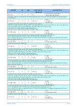
En VTSorCh Fail
En VTSandCh Fail
[Indexed String]
Setting that defines second stage overcurrent operating status. Depending on this setting, I>2 will be enabled permanently or in case of
Voltage Transformer Supervision (fuse fail) operation, or in case of communication channel fail, or a combination (and /or) of both.
I>2 Function
35
0B
IEC S Inverse
DT
IEC S Inverse
IEC V Inverse
IEC E Inverse
UK LT Inverse
IEEE M Inverse
IEEE V Inverse
IEEE E Inverse
US Inverse
US ST Inverse
Default Curve 1
Default Curve 2
Default Curve 3
Default Curve 4
[Indexed String]
Setting for the tripping characteristic for the second stage overcurrent element.
I>2 Directional
35
0C
Non-Directional
Non-Directional
Directional Fwd
Directional Rev
[Indexed String]
This setting determines the direction of measurement for second stage element.
I>2 Current Set
35
0D
1
From 0.08*I1 to 4.0*I1 in steps of 0.01*I1
[Courier Number (current)]
Pick-up setting for second stage overcurrent element.
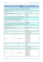
I>2 Time Delay
35
0E
1
From 0 to 100 in steps of 0.01
[Courier Number (time-seconds)]
Setting for the time-delay for the definite time setting if selected for second stage element. The setting is visible only when DT function is
selected.
I>2 TMS
35
0F
1
From 0.025 to 1.2 in steps of 0.005
[Courier Number (decimal)]
Setting for the time multiplier setting to adjust the operating time of the IEC IDMT characteristic.
I>2 Time Dial
35
10
1
From 0.01 to 100 in steps of 0.01
[Courier Number (decimal)]
Setting for the time multiplier setting to adjust the operating time of the IEEE/US IDMT curves. The Time Dial (TD) is a multiplier on the
standard curve equation, in order to achieve the required tripping time. The reference curve is based on TD = 1.
Care: Certain manufacturer's use a mid-range value of TD = 5 or 7, so it may be necessary to divide by 5 or 7 to achieve parity.
I>2 Reset Char
35
11
DT
DT
Inverse
[Indexed String]
Setting to determine the type of reset/release characteristic of the IEEE/US curves.
I>2 tRESET
35
12
0
From 0 to 100 in steps of 0.01
[Courier Number (time-seconds)]
Setting that determines the reset/release time for definite time reset characteristic
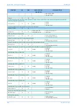
I>3 Status
35
13
Disabled
Disabled
Enabled
Enabled VTS
Enabled Ch Fail
En VTSorCh Fail
En VTSandCh Fail
[Indexed String]
Setting that defines third stage overcurrent operating status. Depending on this setting, I>3 will be enabled permanently or in case of
Voltage Transformer Supervision (fuse fail) operation
I>3 Status
35
13
Disabled
Disabled
Enabled
Enabled VTS
Enabled Ch Fail
Summary of Contents for P4A
Page 2: ......
Page 20: ...Contents P54A B C E xviii P54xMED TM EN 1 ...
Page 27: ...CHAPTER 1 INTRODUCTION ...
Page 28: ...Chapter 1 Introduction P54A B C E 2 P54xMED TM EN 1 ...
Page 38: ...Chapter 1 Introduction P54A B C E 12 P54xMED TM EN 1 ...
Page 39: ...CHAPTER 2 SAFETY INFORMATION ...
Page 40: ...Chapter 2 Safety Information P54A B C E 14 P54xMED TM EN 1 ...
Page 52: ...Chapter 2 Safety Information P54A B C E 26 P54xMED TM EN 1 ...
Page 53: ...CHAPTER 3 HARDWARE DESIGN ...
Page 54: ...Chapter 3 Hardware Design P54A B C E 28 P54xMED TM EN 1 ...
Page 86: ...Chapter 3 Hardware Design P54A B C E 60 P54xMED TM EN 1 ...
Page 87: ...CHAPTER 4 SOFTWARE DESIGN ...
Page 88: ...Chapter 4 Software Design P54A B C E 62 P54xMED TM EN 1 ...
Page 99: ...CHAPTER 5 CONFIGURATION ...
Page 100: ...Chapter 5 Configuration P54A B C E 74 P54xMED TM EN 1 ...
Page 120: ...Chapter 5 Configuration P54A B C E 94 P54xMED TM EN 1 ...
Page 121: ...CHAPTER 6 CURRENT DIFFERENTIAL PROTECTION ...
Page 122: ...Chapter 6 Current Differential Protection P54A B C E 96 P54xMED TM EN 1 ...
Page 149: ...CHAPTER 7 AUTORECLOSE ...
Page 150: ...Chapter 7 Autoreclose P54A B C E 124 P54xMED TM EN 1 ...
Page 207: ...CHAPTER 8 CB FAIL PROTECTION ...
Page 208: ...Chapter 8 CB Fail Protection P54A B C E 182 P54xMED TM EN 1 ...
Page 219: ...CHAPTER 9 CURRENT PROTECTION FUNCTIONS ...
Page 220: ...Chapter 9 Current Protection Functions P54A B C E 194 P54xMED TM EN 1 ...
Page 244: ...Chapter 9 Current Protection Functions P54A B C E 218 P54xMED TM EN 1 ...
Page 247: ...CHAPTER 10 VOLTAGE PROTECTION FUNCTIONS ...
Page 248: ...Chapter 10 Voltage Protection Functions P54A B C E 222 P54xMED TM EN 1 ...
Page 261: ...CHAPTER 11 FREQUENCY PROTECTION FUNCTIONS ...
Page 262: ...Chapter 11 Frequency Protection Functions P54A B C E 236 P54xMED TM EN 1 ...
Page 268: ...Chapter 11 Frequency Protection Functions P54A B C E 242 P54xMED TM EN 1 ...
Page 269: ...CHAPTER 12 MONITORING AND CONTROL ...
Page 270: ...Chapter 12 Monitoring and Control P54A B C E 244 P54xMED TM EN 1 ...
Page 300: ...Chapter 12 Monitoring and Control P54A B C E 274 P54xMED TM EN 1 ...
Page 301: ...CHAPTER 13 SUPERVISION ...
Page 302: ...Chapter 13 Supervision P54A B C E 276 P54xMED TM EN 1 ...
Page 312: ...Chapter 13 Supervision P54A B C E 286 P54xMED TM EN 1 ...
Page 323: ...CHAPTER 14 DIGITAL I O AND PSL CONFIGURATION ...
Page 324: ...Chapter 14 Digital I O and PSL Configuration P54A B C E 298 P54xMED TM EN 1 ...
Page 336: ...Chapter 14 Digital I O and PSL Configuration P54A B C E 310 P54xMED TM EN 1 ...
Page 337: ...CHAPTER 15 FIBRE TELEPROTECTION ...
Page 338: ...Chapter 15 Fibre Teleprotection P54A B C E 312 P54xMED TM EN 1 ...
Page 354: ...Chapter 15 Fibre Teleprotection P54A B C E 328 P54xMED TM EN 1 ...
Page 355: ...CHAPTER 16 ELECTRICAL TELEPROTECTION ...
Page 356: ...Chapter 16 Electrical Teleprotection P54A B C E 330 P54xMED TM EN 1 ...
Page 366: ...Chapter 16 Electrical Teleprotection P54A B C E 340 P54xMED TM EN 1 ...
Page 367: ...CHAPTER 17 COMMUNICATIONS ...
Page 368: ...Chapter 17 Communications P54A B C E 342 P54xMED TM EN 1 ...
Page 439: ...CHAPTER 18 CYBER SECURITY ...
Page 440: ...Chapter 18 Cyber Security P54A B C E 414 P54xMED TM EN 1 ...
Page 457: ...CHAPTER 19 INSTALLATION ...
Page 458: ...Chapter 19 Installation P54A B C E 432 P54xMED TM EN 1 ...
Page 471: ...CHAPTER 20 COMMISSIONING INSTRUCTIONS ...
Page 472: ...Chapter 20 Commissioning Instructions P54A B C E 446 P54xMED TM EN 1 ...
Page 513: ...CHAPTER 21 MAINTENANCE AND TROUBLESHOOTING ...
Page 514: ...Chapter 21 Maintenance and Troubleshooting P54A B C E 488 P54xMED TM EN 1 ...
Page 530: ...Chapter 21 Maintenance and Troubleshooting P54A B C E 504 P54xMED TM EN 1 ...
Page 531: ...CHAPTER 22 TECHNICAL SPECIFICATIONS ...
Page 532: ...Chapter 22 Technical Specifications P54A B C E 506 P54xMED TM EN 1 ...
Page 558: ...Chapter 22 Technical Specifications P54A B C E 532 P54xMED TM EN 1 ...
Page 559: ...APPENDIX A ORDERING OPTIONS ...
Page 560: ...Appendix A Ordering Options P54A B C E P54xMED TM EN 1 ...
Page 565: ...APPENDIX B SETTINGS AND SIGNALS ...
Page 566: ...Appendix B Settings and Signals P54A B C E P54xMED TM EN 1 ...
Page 790: ...Appendix B Settings and Signals P54A B C E B224 P54xMED TM EN 1 ...
Page 835: ...APPENDIX C WIRING DIAGRAMS ...
Page 836: ...Appendix C Wiring Diagrams P54A B C E P54xMED TM EN 1 ...
Page 849: ......