


Appendix B - Settings and Signals
P54A/B/C/E
B170
P54xMED-TM-EN-1
MENU TEXT
COL
ROW
DEFAULT SETTING
AVAILABLE OPTIONS
DESCRIPTION
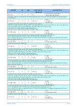
If Ph Diff Stub Bus is enabled, DDB input signal Stub Bus Enabled is energised and phase current is measured above Ph Is1 Stub Bus setting,
the IED will issue a Stub Bus Trip
Ph Is1 StubBus
33
84
2.0*l1
From 0.1*l1 to 12*l1 in steps of 0.01*l1
[Courier Number (current)]
The threshold of operation as there is no effective bias when operating in this mode.
Phase Is1 CTS
33
85
1.2*l1
From 0.2*I1 to 4*I1 in steps of 0.05*I1
[Courier Number (current)]
Setting that defines the minimum pick-up level of the IED when a current transformer supervision CTS is declared
TRIP ON CLOSE
33
96
Trip on Close/SOTF Sub Heading
SOTF Status
33
97
Enabled PoleDead
Disabled
Enabled PoleDead
Enabled ExtPulse
En Pdead + Pulse
[Indexed String]
Setting that enables note (turns on) or disables (turns off) a special protection logic which can apply upon line energization. SOTF = Switch
on to Fault.
Note: SOTF can be enabled in three different manners:
1. Enabled Pole Dead. By using pole dead logic detection logic
2. Enabled ExtPulse. By using an external pulse
3. En Pdead + Pulse. By using both
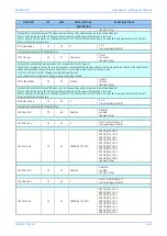
SOTF Delay
33
98
110
From 0.2 to 1000 in steps of 0.05
[Courier Number (time-seconds)]
The SOTF Delay is a pick up time delay that starts after opening all 3 poles of a CB. If the CB is then closed after the set time delay has
expired, SOTF protection will be active. SOTF provides enhanced protection for manual closure of the breaker (not for auto-reclosure).
This setting is visible only if Pole Dead or Pdead + Pulse are selected to enable SOTF.
TOR Status
33
99
Enabled
Disabled
Enabled
[Indexed String]
Setting that enables (turns on) or disables (turns off) special protection following
auto-reclosure. When set Enabled, TOR will be activated after the ‘TOC Delay’ has expired, ready for application when an auto-reclose shot
occurs. TOR = Trip on (auto)Reclose.
TOC Reset Delay
33
9A
0.5
From 0.1 to 2s in steps of 0.1
[Courier Number (time-seconds)]
The TOC Reset Delay is a user settable time window during which TOC protection is available. The time window starts timing upon CB closure
and it is common for SOTF and TOR protection. Once this timer expires after a successful (re)closure, all protection reverts to normal.
SOTF Pulse
33
9B
0.5
From 0.1 to 10s in steps of 0.01
[Courier Number (time-seconds)]
The SOTF Pulse is a user settable time window during which the SOTF protection is available. This setting is visible only if ExtPulse or Pdead +
Pulse are selected to enable SOTF
TOC Delay
33
9C
0.2
From 0.05 to 0.2 in steps of 0.01
[Courier Number (time-seconds)]
The TOC Delay is a user settable time delay following the CB opening after which the TOR becomes active (enabled). The time must be set in
conjunction with the Dead Time setting of the Auto-reclose so that the setting must not exceed the minimum Dead Time setting since both
timers start instantaneously.
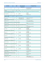
GROUP 1:
OVERCURRENT
35
00
This column contains settings for Overcurrent
I>1 Status
35
01
Enabled
Disabled
Enabled
Enabled VTS
Enabled Ch Fail
En VTSorCh Fail
En VTSandCh Fail
[Indexed String]
Setting that defines first stage overcurrent operating status. Depending on this setting, I>1 will be enabled permanently or in case of Voltage
Transformer Supervision (fuse fail) operation
I>1 Status
35
01
Enabled
Disabled
Enabled
Enabled VTS
Enabled Ch Fail
Summary of Contents for P4A
Page 2: ......
Page 20: ...Contents P54A B C E xviii P54xMED TM EN 1 ...
Page 27: ...CHAPTER 1 INTRODUCTION ...
Page 28: ...Chapter 1 Introduction P54A B C E 2 P54xMED TM EN 1 ...
Page 38: ...Chapter 1 Introduction P54A B C E 12 P54xMED TM EN 1 ...
Page 39: ...CHAPTER 2 SAFETY INFORMATION ...
Page 40: ...Chapter 2 Safety Information P54A B C E 14 P54xMED TM EN 1 ...
Page 52: ...Chapter 2 Safety Information P54A B C E 26 P54xMED TM EN 1 ...
Page 53: ...CHAPTER 3 HARDWARE DESIGN ...
Page 54: ...Chapter 3 Hardware Design P54A B C E 28 P54xMED TM EN 1 ...
Page 86: ...Chapter 3 Hardware Design P54A B C E 60 P54xMED TM EN 1 ...
Page 87: ...CHAPTER 4 SOFTWARE DESIGN ...
Page 88: ...Chapter 4 Software Design P54A B C E 62 P54xMED TM EN 1 ...
Page 99: ...CHAPTER 5 CONFIGURATION ...
Page 100: ...Chapter 5 Configuration P54A B C E 74 P54xMED TM EN 1 ...
Page 120: ...Chapter 5 Configuration P54A B C E 94 P54xMED TM EN 1 ...
Page 121: ...CHAPTER 6 CURRENT DIFFERENTIAL PROTECTION ...
Page 122: ...Chapter 6 Current Differential Protection P54A B C E 96 P54xMED TM EN 1 ...
Page 149: ...CHAPTER 7 AUTORECLOSE ...
Page 150: ...Chapter 7 Autoreclose P54A B C E 124 P54xMED TM EN 1 ...
Page 207: ...CHAPTER 8 CB FAIL PROTECTION ...
Page 208: ...Chapter 8 CB Fail Protection P54A B C E 182 P54xMED TM EN 1 ...
Page 219: ...CHAPTER 9 CURRENT PROTECTION FUNCTIONS ...
Page 220: ...Chapter 9 Current Protection Functions P54A B C E 194 P54xMED TM EN 1 ...
Page 244: ...Chapter 9 Current Protection Functions P54A B C E 218 P54xMED TM EN 1 ...
Page 247: ...CHAPTER 10 VOLTAGE PROTECTION FUNCTIONS ...
Page 248: ...Chapter 10 Voltage Protection Functions P54A B C E 222 P54xMED TM EN 1 ...
Page 261: ...CHAPTER 11 FREQUENCY PROTECTION FUNCTIONS ...
Page 262: ...Chapter 11 Frequency Protection Functions P54A B C E 236 P54xMED TM EN 1 ...
Page 268: ...Chapter 11 Frequency Protection Functions P54A B C E 242 P54xMED TM EN 1 ...
Page 269: ...CHAPTER 12 MONITORING AND CONTROL ...
Page 270: ...Chapter 12 Monitoring and Control P54A B C E 244 P54xMED TM EN 1 ...
Page 300: ...Chapter 12 Monitoring and Control P54A B C E 274 P54xMED TM EN 1 ...
Page 301: ...CHAPTER 13 SUPERVISION ...
Page 302: ...Chapter 13 Supervision P54A B C E 276 P54xMED TM EN 1 ...
Page 312: ...Chapter 13 Supervision P54A B C E 286 P54xMED TM EN 1 ...
Page 323: ...CHAPTER 14 DIGITAL I O AND PSL CONFIGURATION ...
Page 324: ...Chapter 14 Digital I O and PSL Configuration P54A B C E 298 P54xMED TM EN 1 ...
Page 336: ...Chapter 14 Digital I O and PSL Configuration P54A B C E 310 P54xMED TM EN 1 ...
Page 337: ...CHAPTER 15 FIBRE TELEPROTECTION ...
Page 338: ...Chapter 15 Fibre Teleprotection P54A B C E 312 P54xMED TM EN 1 ...
Page 354: ...Chapter 15 Fibre Teleprotection P54A B C E 328 P54xMED TM EN 1 ...
Page 355: ...CHAPTER 16 ELECTRICAL TELEPROTECTION ...
Page 356: ...Chapter 16 Electrical Teleprotection P54A B C E 330 P54xMED TM EN 1 ...
Page 366: ...Chapter 16 Electrical Teleprotection P54A B C E 340 P54xMED TM EN 1 ...
Page 367: ...CHAPTER 17 COMMUNICATIONS ...
Page 368: ...Chapter 17 Communications P54A B C E 342 P54xMED TM EN 1 ...
Page 439: ...CHAPTER 18 CYBER SECURITY ...
Page 440: ...Chapter 18 Cyber Security P54A B C E 414 P54xMED TM EN 1 ...
Page 457: ...CHAPTER 19 INSTALLATION ...
Page 458: ...Chapter 19 Installation P54A B C E 432 P54xMED TM EN 1 ...
Page 471: ...CHAPTER 20 COMMISSIONING INSTRUCTIONS ...
Page 472: ...Chapter 20 Commissioning Instructions P54A B C E 446 P54xMED TM EN 1 ...
Page 513: ...CHAPTER 21 MAINTENANCE AND TROUBLESHOOTING ...
Page 514: ...Chapter 21 Maintenance and Troubleshooting P54A B C E 488 P54xMED TM EN 1 ...
Page 530: ...Chapter 21 Maintenance and Troubleshooting P54A B C E 504 P54xMED TM EN 1 ...
Page 531: ...CHAPTER 22 TECHNICAL SPECIFICATIONS ...
Page 532: ...Chapter 22 Technical Specifications P54A B C E 506 P54xMED TM EN 1 ...
Page 558: ...Chapter 22 Technical Specifications P54A B C E 532 P54xMED TM EN 1 ...
Page 559: ...APPENDIX A ORDERING OPTIONS ...
Page 560: ...Appendix A Ordering Options P54A B C E P54xMED TM EN 1 ...
Page 565: ...APPENDIX B SETTINGS AND SIGNALS ...
Page 566: ...Appendix B Settings and Signals P54A B C E P54xMED TM EN 1 ...
Page 790: ...Appendix B Settings and Signals P54A B C E B224 P54xMED TM EN 1 ...
Page 835: ...APPENDIX C WIRING DIAGRAMS ...
Page 836: ...Appendix C Wiring Diagrams P54A B C E P54xMED TM EN 1 ...
Page 849: ......