


P54A/B/C/E
Appendix B - Settings and Signals
P54xMED-TM-EN-1
B167
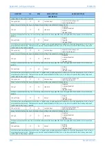
MENU TEXT
COL
ROW
DEFAULT SETTING
AVAILABLE OPTIONS
DESCRIPTION
T6 J3
T1 J4
T2 J4
T3 J4
T4 J4
T5 J4
T6 J4
[Binary Flag (24) & Indexed String]
A map of the terminals and junctions in the system for P541 only
Length Local
30
22
45000
From 100 to 10000000 in steps of 10
[Courier Number (metres)]
Length of the local terminal section in KM
Length Local
30
23
28000
From 0.06 to 621 in steps of 0.005
[Courier Number (miles)]
Length of the local terminal section in miles
Length J1-J2
30
24
100000
From 100 to 10000000 in steps of 10
[Courier Number (metres)]
Distance between junction 1 and 2 when it is a mult-junction network in KM
Length J1-J2
30
25
62.1
From 0.06 to 621 in steps of 0.005
[Courier Number (miles)]
Distance between junction 1 and 2 when it is a mult-junction network in KM
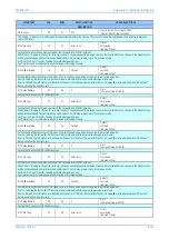
Length J2-J3
30
26
100000
From 100 to 10000000 in steps of 10
[Courier Number (metres)]
Distance between junction 2 and 3 when it is a multi-junction network in KM
Length J2-J3
30
27
62.1
From 0.06 to 621 in steps of 0.005
[Courier Number (miles)]
Distance between junction 2 and 3 when it is a multi-junction network in KM
Length J3-J4
30
28
100000
From 100 to 10000000 in steps of 10
[Courier Number (metres)]
Distance between junctions 3 and 4 when it is a multi-junction network in KM
Length J3-J4
30
29
62.1
From 0.06 to 621 in steps of 0.005
[Courier Number (miles)]
Distance between junctions 3 and 4 when it is a multi-junction network in KM
Line Type Local
30
2A
UnderGndCable
OverheadLine
[Indexed String]
This setting is used to select the overhead line or the underground cable. If it is overhead line, the admittance parameters will be invisiable,
they will be deduced via fomular
Z1Local
30
2B
8
From 0.05*v1/I1 to 500*V1/I1 in steps of 0.01*V1/I1
[Courier Number (impedance)]
Positive sequence impedance amplitude of the local section length per KM
Z1LocalAngle
30
2C
70
From 0 to 10 in steps of 0.01
[Courier Number (angle)]
Positive Sequence impedance angle of the local section length
Z0Local
30
2D
8
From 0.05*v1/I1 to 500*V1/I1 in steps of 0.01*V1/I1
[Courier Number (impedance)]
Zero Sequence impedance amplitude of the local section length
Z0LocalAngle
30
2E
70
From 0 to 10 in steps of 1
[Courier Number (angle)]
Zero Sequence impedance angle of the local section length
Y1Local
30
2F
0.00000001*I1
From 0.00000001*I1 to 10*I1 in steps of
0.00000001*I1
[Courier Number (inverse ohms)]
Positive sequence admittance amplitude of the local section length (the conductance is neglected)
Y0Local
30
30
0.00000001*I1
From 0.00000001*I1 to 10*I1 in steps of
0.00000001*I1
[Courier Number (inverse ohms)]
Zero sequence admittance amplitude of the local section length (the conductance is neglected)
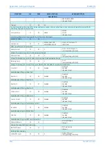
Line Type J1-J2
30
31
UnderGndCable
OverheadLine
[Indexed String]
This setting is used to select the overhead line or the underground cable. If it is overhead line, the admittance parameters will be invisiable,
Summary of Contents for P4A
Page 2: ......
Page 20: ...Contents P54A B C E xviii P54xMED TM EN 1 ...
Page 27: ...CHAPTER 1 INTRODUCTION ...
Page 28: ...Chapter 1 Introduction P54A B C E 2 P54xMED TM EN 1 ...
Page 38: ...Chapter 1 Introduction P54A B C E 12 P54xMED TM EN 1 ...
Page 39: ...CHAPTER 2 SAFETY INFORMATION ...
Page 40: ...Chapter 2 Safety Information P54A B C E 14 P54xMED TM EN 1 ...
Page 52: ...Chapter 2 Safety Information P54A B C E 26 P54xMED TM EN 1 ...
Page 53: ...CHAPTER 3 HARDWARE DESIGN ...
Page 54: ...Chapter 3 Hardware Design P54A B C E 28 P54xMED TM EN 1 ...
Page 86: ...Chapter 3 Hardware Design P54A B C E 60 P54xMED TM EN 1 ...
Page 87: ...CHAPTER 4 SOFTWARE DESIGN ...
Page 88: ...Chapter 4 Software Design P54A B C E 62 P54xMED TM EN 1 ...
Page 99: ...CHAPTER 5 CONFIGURATION ...
Page 100: ...Chapter 5 Configuration P54A B C E 74 P54xMED TM EN 1 ...
Page 120: ...Chapter 5 Configuration P54A B C E 94 P54xMED TM EN 1 ...
Page 121: ...CHAPTER 6 CURRENT DIFFERENTIAL PROTECTION ...
Page 122: ...Chapter 6 Current Differential Protection P54A B C E 96 P54xMED TM EN 1 ...
Page 149: ...CHAPTER 7 AUTORECLOSE ...
Page 150: ...Chapter 7 Autoreclose P54A B C E 124 P54xMED TM EN 1 ...
Page 207: ...CHAPTER 8 CB FAIL PROTECTION ...
Page 208: ...Chapter 8 CB Fail Protection P54A B C E 182 P54xMED TM EN 1 ...
Page 219: ...CHAPTER 9 CURRENT PROTECTION FUNCTIONS ...
Page 220: ...Chapter 9 Current Protection Functions P54A B C E 194 P54xMED TM EN 1 ...
Page 244: ...Chapter 9 Current Protection Functions P54A B C E 218 P54xMED TM EN 1 ...
Page 247: ...CHAPTER 10 VOLTAGE PROTECTION FUNCTIONS ...
Page 248: ...Chapter 10 Voltage Protection Functions P54A B C E 222 P54xMED TM EN 1 ...
Page 261: ...CHAPTER 11 FREQUENCY PROTECTION FUNCTIONS ...
Page 262: ...Chapter 11 Frequency Protection Functions P54A B C E 236 P54xMED TM EN 1 ...
Page 268: ...Chapter 11 Frequency Protection Functions P54A B C E 242 P54xMED TM EN 1 ...
Page 269: ...CHAPTER 12 MONITORING AND CONTROL ...
Page 270: ...Chapter 12 Monitoring and Control P54A B C E 244 P54xMED TM EN 1 ...
Page 300: ...Chapter 12 Monitoring and Control P54A B C E 274 P54xMED TM EN 1 ...
Page 301: ...CHAPTER 13 SUPERVISION ...
Page 302: ...Chapter 13 Supervision P54A B C E 276 P54xMED TM EN 1 ...
Page 312: ...Chapter 13 Supervision P54A B C E 286 P54xMED TM EN 1 ...
Page 323: ...CHAPTER 14 DIGITAL I O AND PSL CONFIGURATION ...
Page 324: ...Chapter 14 Digital I O and PSL Configuration P54A B C E 298 P54xMED TM EN 1 ...
Page 336: ...Chapter 14 Digital I O and PSL Configuration P54A B C E 310 P54xMED TM EN 1 ...
Page 337: ...CHAPTER 15 FIBRE TELEPROTECTION ...
Page 338: ...Chapter 15 Fibre Teleprotection P54A B C E 312 P54xMED TM EN 1 ...
Page 354: ...Chapter 15 Fibre Teleprotection P54A B C E 328 P54xMED TM EN 1 ...
Page 355: ...CHAPTER 16 ELECTRICAL TELEPROTECTION ...
Page 356: ...Chapter 16 Electrical Teleprotection P54A B C E 330 P54xMED TM EN 1 ...
Page 366: ...Chapter 16 Electrical Teleprotection P54A B C E 340 P54xMED TM EN 1 ...
Page 367: ...CHAPTER 17 COMMUNICATIONS ...
Page 368: ...Chapter 17 Communications P54A B C E 342 P54xMED TM EN 1 ...
Page 439: ...CHAPTER 18 CYBER SECURITY ...
Page 440: ...Chapter 18 Cyber Security P54A B C E 414 P54xMED TM EN 1 ...
Page 457: ...CHAPTER 19 INSTALLATION ...
Page 458: ...Chapter 19 Installation P54A B C E 432 P54xMED TM EN 1 ...
Page 471: ...CHAPTER 20 COMMISSIONING INSTRUCTIONS ...
Page 472: ...Chapter 20 Commissioning Instructions P54A B C E 446 P54xMED TM EN 1 ...
Page 513: ...CHAPTER 21 MAINTENANCE AND TROUBLESHOOTING ...
Page 514: ...Chapter 21 Maintenance and Troubleshooting P54A B C E 488 P54xMED TM EN 1 ...
Page 530: ...Chapter 21 Maintenance and Troubleshooting P54A B C E 504 P54xMED TM EN 1 ...
Page 531: ...CHAPTER 22 TECHNICAL SPECIFICATIONS ...
Page 532: ...Chapter 22 Technical Specifications P54A B C E 506 P54xMED TM EN 1 ...
Page 558: ...Chapter 22 Technical Specifications P54A B C E 532 P54xMED TM EN 1 ...
Page 559: ...APPENDIX A ORDERING OPTIONS ...
Page 560: ...Appendix A Ordering Options P54A B C E P54xMED TM EN 1 ...
Page 565: ...APPENDIX B SETTINGS AND SIGNALS ...
Page 566: ...Appendix B Settings and Signals P54A B C E P54xMED TM EN 1 ...
Page 790: ...Appendix B Settings and Signals P54A B C E B224 P54xMED TM EN 1 ...
Page 835: ...APPENDIX C WIRING DIAGRAMS ...
Page 836: ...Appendix C Wiring Diagrams P54A B C E P54xMED TM EN 1 ...
Page 849: ......