


P54A/B/C/E
Appendix B - Settings and Signals
P54xMED-TM-EN-1
B165
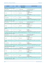
MENU TEXT
COL
ROW
DEFAULT SETTING
AVAILABLE OPTIONS
DESCRIPTION
[ASCII Text (16 chars)]
Text label to describe each individual control input. This text is displayed when a control input is accessed by the hotkey menu. It is displayed
in the programmable scheme logic description of the control input
Control Input 30
29
1E
Control Input 30
From 32 to 163 in steps of 1
[ASCII Text (16 chars)]
Text label to describe each individual control input. This text is displayed when a control input is accessed by the hotkey menu. It is displayed
in the programmable scheme logic description of the control input
Control Input 31
29
1F
Control Input 31
Text label to describe each individual control input. This text is displayed when a control input is accessed by the hotkey menu. It is displayed
in the programmable scheme logic description of the control input
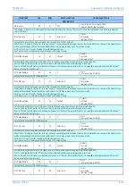
GROUP 1: LINE
PARAMETERS
30
00
This column contains settings for Line Parameters
Line Length
30
01
100000
From 300 to 1000000 in steps of 10
[Courier Number (metres)]
Setting of the protected line/cable length in km. This setting is available if MEASURE’T SETUP column is selected as Visible in the
CONFIGURATION column and if Distance unit in the MEASURE’T SETUP column is selected as kilometres
Line Length
30
02
62.1
From 0.05 to 621 in steps of 0.005
[Courier Number (miles)]
Setting of the protected line/cable length in miles. This setting is available if Distance unit in the MEASURE’T SETUP column is selected as
miles. Dual step size is provided, for cables/short lines up to 10 miles the step size is 0.005 miles, 0.01 miles otherwise
Line Impedance
30
03
10
From 0.05*v1/I1 to 500*V1/I1 in steps of 0.01*V1/I1
[Courier Number (impedance)]
Setting for protected line/cable positive sequence impedance in either primary or secondary terms, depending on the Setting Values
reference chosen in the CONFIGURATION column. The set value is used for Fault locator, and for all distance zone reaches calculation if
‘Simple’ setting mode under GROUP x DISTANCE SETUP is selected.
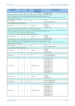
Line Angle
30
04
70
From 20 to 90 in steps of 1
[Courier Number (angle)]
Setting of the line angle (line positive sequence impedance angle).
kZN Res Comp
30
05
1
From 0 to 10 in steps of 0.01
[Courier Number]
Setting of the residual compensation factor magnitude, used to extend the ground loop reach by a multiplication factor of (1+ kZN), is
calculated as ratio:
│
kZN
│
= (Z0 – Z1)/3Z1 where,
Z1 = positive sequence impedance for the protected line or cable.
Z0 = zero sequence impedance for the protected line or cable.
This setting is a used for Distance protection (when set to simple mode) . If Distance protection is set to Advanced mode, there are individual
settings per Zone in the GROUP x DISTANCE ELEMENTS settings.
kZN Res Angle
30
06
0
From -180 to 90 in steps of 1
[Courier Number (angle)]
Setting of the residual compensation factor angle (in degrees) is calculated as:
ÐkZN = Ð (Z0 – Z1)/3Z1 where,
Z1 = positive sequence impedance for the protected line or cable.
Z0 = zero sequence impedance for the protected line or cable.
This setting is a used for Distance protection (when set to simple mode) . If Distance protection is set to Advanced mode, there are individual
settings per Zone in the GROUP x DISTANCE ELEMENTS settings.
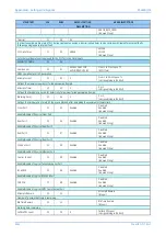
Mutual Comp
30
07
Disabled
Disabled
Enabled
[Indexed String]
To enable (activate) or disable (turn off) the Mutual compensation replica used in both, Distance and Fault locator ground fault loops.
KZm Mutual Set.
30
08
1
From 0 to 10 in steps of 0.01
[Courier Number]
Setting of the mutual compensation factor kZm magnitude is calculated as a ratio:
|kZm| = ZM0/3Z1 where,
ZM0 = zero sequence mutual impedance for the protected line or cable.
Z1 = positive sequence impedance for the protected line or cable.
Setting kZm is visible if ‘Mutual Comp’ is enabled. This setting is a used for fault locator and Distance protection (when set to simple mode) .
If Distance protection is set to Advanced mode, there are individual settings per Zone in the GROUP x DISTANCE ELEMENTS settings.
KZm Mutual Angle
30
09
0
From -180 to 90 in steps of 1
[Courier Number (angle)]
Setting of the mutual compensation angle (in degrees) is calculated as:
Summary of Contents for P4A
Page 2: ......
Page 20: ...Contents P54A B C E xviii P54xMED TM EN 1 ...
Page 27: ...CHAPTER 1 INTRODUCTION ...
Page 28: ...Chapter 1 Introduction P54A B C E 2 P54xMED TM EN 1 ...
Page 38: ...Chapter 1 Introduction P54A B C E 12 P54xMED TM EN 1 ...
Page 39: ...CHAPTER 2 SAFETY INFORMATION ...
Page 40: ...Chapter 2 Safety Information P54A B C E 14 P54xMED TM EN 1 ...
Page 52: ...Chapter 2 Safety Information P54A B C E 26 P54xMED TM EN 1 ...
Page 53: ...CHAPTER 3 HARDWARE DESIGN ...
Page 54: ...Chapter 3 Hardware Design P54A B C E 28 P54xMED TM EN 1 ...
Page 86: ...Chapter 3 Hardware Design P54A B C E 60 P54xMED TM EN 1 ...
Page 87: ...CHAPTER 4 SOFTWARE DESIGN ...
Page 88: ...Chapter 4 Software Design P54A B C E 62 P54xMED TM EN 1 ...
Page 99: ...CHAPTER 5 CONFIGURATION ...
Page 100: ...Chapter 5 Configuration P54A B C E 74 P54xMED TM EN 1 ...
Page 120: ...Chapter 5 Configuration P54A B C E 94 P54xMED TM EN 1 ...
Page 121: ...CHAPTER 6 CURRENT DIFFERENTIAL PROTECTION ...
Page 122: ...Chapter 6 Current Differential Protection P54A B C E 96 P54xMED TM EN 1 ...
Page 149: ...CHAPTER 7 AUTORECLOSE ...
Page 150: ...Chapter 7 Autoreclose P54A B C E 124 P54xMED TM EN 1 ...
Page 207: ...CHAPTER 8 CB FAIL PROTECTION ...
Page 208: ...Chapter 8 CB Fail Protection P54A B C E 182 P54xMED TM EN 1 ...
Page 219: ...CHAPTER 9 CURRENT PROTECTION FUNCTIONS ...
Page 220: ...Chapter 9 Current Protection Functions P54A B C E 194 P54xMED TM EN 1 ...
Page 244: ...Chapter 9 Current Protection Functions P54A B C E 218 P54xMED TM EN 1 ...
Page 247: ...CHAPTER 10 VOLTAGE PROTECTION FUNCTIONS ...
Page 248: ...Chapter 10 Voltage Protection Functions P54A B C E 222 P54xMED TM EN 1 ...
Page 261: ...CHAPTER 11 FREQUENCY PROTECTION FUNCTIONS ...
Page 262: ...Chapter 11 Frequency Protection Functions P54A B C E 236 P54xMED TM EN 1 ...
Page 268: ...Chapter 11 Frequency Protection Functions P54A B C E 242 P54xMED TM EN 1 ...
Page 269: ...CHAPTER 12 MONITORING AND CONTROL ...
Page 270: ...Chapter 12 Monitoring and Control P54A B C E 244 P54xMED TM EN 1 ...
Page 300: ...Chapter 12 Monitoring and Control P54A B C E 274 P54xMED TM EN 1 ...
Page 301: ...CHAPTER 13 SUPERVISION ...
Page 302: ...Chapter 13 Supervision P54A B C E 276 P54xMED TM EN 1 ...
Page 312: ...Chapter 13 Supervision P54A B C E 286 P54xMED TM EN 1 ...
Page 323: ...CHAPTER 14 DIGITAL I O AND PSL CONFIGURATION ...
Page 324: ...Chapter 14 Digital I O and PSL Configuration P54A B C E 298 P54xMED TM EN 1 ...
Page 336: ...Chapter 14 Digital I O and PSL Configuration P54A B C E 310 P54xMED TM EN 1 ...
Page 337: ...CHAPTER 15 FIBRE TELEPROTECTION ...
Page 338: ...Chapter 15 Fibre Teleprotection P54A B C E 312 P54xMED TM EN 1 ...
Page 354: ...Chapter 15 Fibre Teleprotection P54A B C E 328 P54xMED TM EN 1 ...
Page 355: ...CHAPTER 16 ELECTRICAL TELEPROTECTION ...
Page 356: ...Chapter 16 Electrical Teleprotection P54A B C E 330 P54xMED TM EN 1 ...
Page 366: ...Chapter 16 Electrical Teleprotection P54A B C E 340 P54xMED TM EN 1 ...
Page 367: ...CHAPTER 17 COMMUNICATIONS ...
Page 368: ...Chapter 17 Communications P54A B C E 342 P54xMED TM EN 1 ...
Page 439: ...CHAPTER 18 CYBER SECURITY ...
Page 440: ...Chapter 18 Cyber Security P54A B C E 414 P54xMED TM EN 1 ...
Page 457: ...CHAPTER 19 INSTALLATION ...
Page 458: ...Chapter 19 Installation P54A B C E 432 P54xMED TM EN 1 ...
Page 471: ...CHAPTER 20 COMMISSIONING INSTRUCTIONS ...
Page 472: ...Chapter 20 Commissioning Instructions P54A B C E 446 P54xMED TM EN 1 ...
Page 513: ...CHAPTER 21 MAINTENANCE AND TROUBLESHOOTING ...
Page 514: ...Chapter 21 Maintenance and Troubleshooting P54A B C E 488 P54xMED TM EN 1 ...
Page 530: ...Chapter 21 Maintenance and Troubleshooting P54A B C E 504 P54xMED TM EN 1 ...
Page 531: ...CHAPTER 22 TECHNICAL SPECIFICATIONS ...
Page 532: ...Chapter 22 Technical Specifications P54A B C E 506 P54xMED TM EN 1 ...
Page 558: ...Chapter 22 Technical Specifications P54A B C E 532 P54xMED TM EN 1 ...
Page 559: ...APPENDIX A ORDERING OPTIONS ...
Page 560: ...Appendix A Ordering Options P54A B C E P54xMED TM EN 1 ...
Page 565: ...APPENDIX B SETTINGS AND SIGNALS ...
Page 566: ...Appendix B Settings and Signals P54A B C E P54xMED TM EN 1 ...
Page 790: ...Appendix B Settings and Signals P54A B C E B224 P54xMED TM EN 1 ...
Page 835: ...APPENDIX C WIRING DIAGRAMS ...
Page 836: ...Appendix C Wiring Diagrams P54A B C E P54xMED TM EN 1 ...
Page 849: ......