


Appendix B - Settings and Signals
P54A/B/C/E
B148
P54xMED-TM-EN-1
MENU TEXT
COL
ROW
DEFAULT SETTING
AVAILABLE OPTIONS
DESCRIPTION
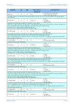
Allows the SET / RESET text, displayed in the hotkey menu, to be changed to something more suitable for the application of an individual
control input, such as ON / OFF, IN / OUT etc.
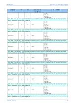
INTERMICOM COMMS
15
00
This column is only visible if the model number supports InterMiCOM and second rear comms board is fitted.
IM Output Status
15
01
Data
IM Output Status
[Binary Flags (8 bits)]
Displays the status of each InterMiCOM output signal.
IM Input Status
15
02
Data
IM Input Status
[Binary Flags (8 bits)]
Displays the status of each InterMiCOM input signal, with IM1 signal starting from the right. When loop back mode is set, all bits will display
zero.
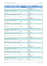
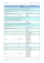
Source Address
15
10
1
From 0 to 10 in steps of 1
[Unsigned Integer(16 bit)]
Setting for the unique IED address that is encoded in the InterMiCOM sent message.
Receive Address
15
11
2
From 0 to 10 in steps of 1
[Unsigned Integer(16 bit)]
The aim of setting addresses is to establish pairs of IED's which will only communicate with each other. Should an inadvertent channel
misrouting or spurious loopback occur, an error will be logged, and the erroneous received data will be rejected.
As an example, in a 2 ended scheme the following address setting would be correct:
Local IED: Source Address = 1, Receive Address = 2
Remote IED: Source Address = 2, Receive Address = 1
Baud Rate
15
12
9600
600
1200
2400
4800
9600
19200
[Indexed String]
Setting of the signalling speed in terms of number of bits per second. The speed will match the capability of the MODEM or other
characteristics of the channel provided.
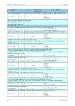
Ch Statistics
15
20
Invisible
Invisible
Visible
[Indexed String]
Settings that makes visible or invisible Channel Statistics on the LCD. The statistic is reset by either IED’s powering down or using the ‘Reset
Statistics’ cell.
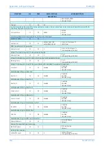
Rx Direct Count
15
21
Rx Direct Count
[Unsigned Integer(32 bit)]
Displays the number of valid Direct Tripping messages since last counter reset.
Rx Perm Count
15
22
Rx Perm Count
[Unsigned Integer(32 bit)]
Displays the number of valid Permissive Tripping messages since last counter reset.
Rx Block Count
15
23
Rx Block Count
[Unsigned Integer(32 bit)]
Displays the number of valid Blocking messages since last counter reset.
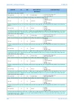
Rx NewData Count
15
24
Rx NewData Count
[Unsigned Integer(32 bit)]
Displays the number of different messages (change events) since last counter reset.
Rx Errored Count
15
25
Rx Errored Count
[Unsigned Integer(32 bit)]
Displays the number of invalid received messages since last counter reset.
Lost Messages
15
26
Lost Messages
[Float]
Displays the difference between the number of messages that were supposed to be received (based on set Baud Rate) and actual valid
received messages since last reset.
Elapsed Time
15
30
Elapsed Time
[Unsigned Integer(32 bit)]
Displays the time in seconds since last counter reset.
Reset Statistics
15
31
No
No
Yes
[Indexed String]
Summary of Contents for P4A
Page 2: ......
Page 20: ...Contents P54A B C E xviii P54xMED TM EN 1 ...
Page 27: ...CHAPTER 1 INTRODUCTION ...
Page 28: ...Chapter 1 Introduction P54A B C E 2 P54xMED TM EN 1 ...
Page 38: ...Chapter 1 Introduction P54A B C E 12 P54xMED TM EN 1 ...
Page 39: ...CHAPTER 2 SAFETY INFORMATION ...
Page 40: ...Chapter 2 Safety Information P54A B C E 14 P54xMED TM EN 1 ...
Page 52: ...Chapter 2 Safety Information P54A B C E 26 P54xMED TM EN 1 ...
Page 53: ...CHAPTER 3 HARDWARE DESIGN ...
Page 54: ...Chapter 3 Hardware Design P54A B C E 28 P54xMED TM EN 1 ...
Page 86: ...Chapter 3 Hardware Design P54A B C E 60 P54xMED TM EN 1 ...
Page 87: ...CHAPTER 4 SOFTWARE DESIGN ...
Page 88: ...Chapter 4 Software Design P54A B C E 62 P54xMED TM EN 1 ...
Page 99: ...CHAPTER 5 CONFIGURATION ...
Page 100: ...Chapter 5 Configuration P54A B C E 74 P54xMED TM EN 1 ...
Page 120: ...Chapter 5 Configuration P54A B C E 94 P54xMED TM EN 1 ...
Page 121: ...CHAPTER 6 CURRENT DIFFERENTIAL PROTECTION ...
Page 122: ...Chapter 6 Current Differential Protection P54A B C E 96 P54xMED TM EN 1 ...
Page 149: ...CHAPTER 7 AUTORECLOSE ...
Page 150: ...Chapter 7 Autoreclose P54A B C E 124 P54xMED TM EN 1 ...
Page 207: ...CHAPTER 8 CB FAIL PROTECTION ...
Page 208: ...Chapter 8 CB Fail Protection P54A B C E 182 P54xMED TM EN 1 ...
Page 219: ...CHAPTER 9 CURRENT PROTECTION FUNCTIONS ...
Page 220: ...Chapter 9 Current Protection Functions P54A B C E 194 P54xMED TM EN 1 ...
Page 244: ...Chapter 9 Current Protection Functions P54A B C E 218 P54xMED TM EN 1 ...
Page 247: ...CHAPTER 10 VOLTAGE PROTECTION FUNCTIONS ...
Page 248: ...Chapter 10 Voltage Protection Functions P54A B C E 222 P54xMED TM EN 1 ...
Page 261: ...CHAPTER 11 FREQUENCY PROTECTION FUNCTIONS ...
Page 262: ...Chapter 11 Frequency Protection Functions P54A B C E 236 P54xMED TM EN 1 ...
Page 268: ...Chapter 11 Frequency Protection Functions P54A B C E 242 P54xMED TM EN 1 ...
Page 269: ...CHAPTER 12 MONITORING AND CONTROL ...
Page 270: ...Chapter 12 Monitoring and Control P54A B C E 244 P54xMED TM EN 1 ...
Page 300: ...Chapter 12 Monitoring and Control P54A B C E 274 P54xMED TM EN 1 ...
Page 301: ...CHAPTER 13 SUPERVISION ...
Page 302: ...Chapter 13 Supervision P54A B C E 276 P54xMED TM EN 1 ...
Page 312: ...Chapter 13 Supervision P54A B C E 286 P54xMED TM EN 1 ...
Page 323: ...CHAPTER 14 DIGITAL I O AND PSL CONFIGURATION ...
Page 324: ...Chapter 14 Digital I O and PSL Configuration P54A B C E 298 P54xMED TM EN 1 ...
Page 336: ...Chapter 14 Digital I O and PSL Configuration P54A B C E 310 P54xMED TM EN 1 ...
Page 337: ...CHAPTER 15 FIBRE TELEPROTECTION ...
Page 338: ...Chapter 15 Fibre Teleprotection P54A B C E 312 P54xMED TM EN 1 ...
Page 354: ...Chapter 15 Fibre Teleprotection P54A B C E 328 P54xMED TM EN 1 ...
Page 355: ...CHAPTER 16 ELECTRICAL TELEPROTECTION ...
Page 356: ...Chapter 16 Electrical Teleprotection P54A B C E 330 P54xMED TM EN 1 ...
Page 366: ...Chapter 16 Electrical Teleprotection P54A B C E 340 P54xMED TM EN 1 ...
Page 367: ...CHAPTER 17 COMMUNICATIONS ...
Page 368: ...Chapter 17 Communications P54A B C E 342 P54xMED TM EN 1 ...
Page 439: ...CHAPTER 18 CYBER SECURITY ...
Page 440: ...Chapter 18 Cyber Security P54A B C E 414 P54xMED TM EN 1 ...
Page 457: ...CHAPTER 19 INSTALLATION ...
Page 458: ...Chapter 19 Installation P54A B C E 432 P54xMED TM EN 1 ...
Page 471: ...CHAPTER 20 COMMISSIONING INSTRUCTIONS ...
Page 472: ...Chapter 20 Commissioning Instructions P54A B C E 446 P54xMED TM EN 1 ...
Page 513: ...CHAPTER 21 MAINTENANCE AND TROUBLESHOOTING ...
Page 514: ...Chapter 21 Maintenance and Troubleshooting P54A B C E 488 P54xMED TM EN 1 ...
Page 530: ...Chapter 21 Maintenance and Troubleshooting P54A B C E 504 P54xMED TM EN 1 ...
Page 531: ...CHAPTER 22 TECHNICAL SPECIFICATIONS ...
Page 532: ...Chapter 22 Technical Specifications P54A B C E 506 P54xMED TM EN 1 ...
Page 558: ...Chapter 22 Technical Specifications P54A B C E 532 P54xMED TM EN 1 ...
Page 559: ...APPENDIX A ORDERING OPTIONS ...
Page 560: ...Appendix A Ordering Options P54A B C E P54xMED TM EN 1 ...
Page 565: ...APPENDIX B SETTINGS AND SIGNALS ...
Page 566: ...Appendix B Settings and Signals P54A B C E P54xMED TM EN 1 ...
Page 790: ...Appendix B Settings and Signals P54A B C E B224 P54xMED TM EN 1 ...
Page 835: ...APPENDIX C WIRING DIAGRAMS ...
Page 836: ...Appendix C Wiring Diagrams P54A B C E P54xMED TM EN 1 ...
Page 849: ......