


4.2
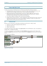
DIFFERENTIAL CTS LOGIC
CT1 L i1>
CT1 R1 i1>
CT1 R2 i1>
>
=
2
CT1 R1 i2/i1>
CT1 R2 i2/i1>
&
CT1 L i2/i1>>
CT1 R2 i2/i1>
CT1 R1 i2/i1>>
CT1 L i2/i1>
CT1 R1 i2/i1>
CT1 R2 i2/i1>>
CT1 L i2/i1>
&
&
1
Disable CTS
Any Trip
Inhibit CTS
&
CTS Block
CT Fail Alarm
V01262
1
CTS Time Delay
Pickup
*In indication mode , timer is set to 20ms
S
R
Q
&
1
&
CTS Reset Mode
Manual
Auto
CTS Status
Restrain
CTS Status
Indication
1
CTS Time Delay
Pickup
S
R
Q
&
CTS Reset Mode
Manual
Auto
Pickup
&
&
CTS Status
Restrain
1
1
CTS Block Diff
CTS Restrain
Remote CT Alarm
CTS Status
Indication
*
Figure 144: Differential CTS
4.3
CTS IMPLEMENTATION
If the power system currents are healthy, no zero sequence voltage are derived. However, if one or more of the AC
current inputs are missing, a zero sequence current would be derived, even if the actual power system phase
currents are healthy. Standard CTS works by detecting a derived zero sequence current where there is no
corresponding derived zero sequence voltage.
The voltage transformer connection used must be able to refer zero sequence voltages from the primary to the
secondary side. Therefore, this element should only be enabled where the VT is of a five-limb construction, or
comprises three single-phase units with the primary star point earthed.
Chapter 13 - Supervision
P54A/B/C/E
290
P54xMED-TM-EN-1
Summary of Contents for P4A
Page 2: ......
Page 20: ...Contents P54A B C E xviii P54xMED TM EN 1 ...
Page 27: ...CHAPTER 1 INTRODUCTION ...
Page 28: ...Chapter 1 Introduction P54A B C E 2 P54xMED TM EN 1 ...
Page 38: ...Chapter 1 Introduction P54A B C E 12 P54xMED TM EN 1 ...
Page 39: ...CHAPTER 2 SAFETY INFORMATION ...
Page 40: ...Chapter 2 Safety Information P54A B C E 14 P54xMED TM EN 1 ...
Page 52: ...Chapter 2 Safety Information P54A B C E 26 P54xMED TM EN 1 ...
Page 53: ...CHAPTER 3 HARDWARE DESIGN ...
Page 54: ...Chapter 3 Hardware Design P54A B C E 28 P54xMED TM EN 1 ...
Page 86: ...Chapter 3 Hardware Design P54A B C E 60 P54xMED TM EN 1 ...
Page 87: ...CHAPTER 4 SOFTWARE DESIGN ...
Page 88: ...Chapter 4 Software Design P54A B C E 62 P54xMED TM EN 1 ...
Page 99: ...CHAPTER 5 CONFIGURATION ...
Page 100: ...Chapter 5 Configuration P54A B C E 74 P54xMED TM EN 1 ...
Page 120: ...Chapter 5 Configuration P54A B C E 94 P54xMED TM EN 1 ...
Page 121: ...CHAPTER 6 CURRENT DIFFERENTIAL PROTECTION ...
Page 122: ...Chapter 6 Current Differential Protection P54A B C E 96 P54xMED TM EN 1 ...
Page 149: ...CHAPTER 7 AUTORECLOSE ...
Page 150: ...Chapter 7 Autoreclose P54A B C E 124 P54xMED TM EN 1 ...
Page 207: ...CHAPTER 8 CB FAIL PROTECTION ...
Page 208: ...Chapter 8 CB Fail Protection P54A B C E 182 P54xMED TM EN 1 ...
Page 219: ...CHAPTER 9 CURRENT PROTECTION FUNCTIONS ...
Page 220: ...Chapter 9 Current Protection Functions P54A B C E 194 P54xMED TM EN 1 ...
Page 244: ...Chapter 9 Current Protection Functions P54A B C E 218 P54xMED TM EN 1 ...
Page 247: ...CHAPTER 10 VOLTAGE PROTECTION FUNCTIONS ...
Page 248: ...Chapter 10 Voltage Protection Functions P54A B C E 222 P54xMED TM EN 1 ...
Page 261: ...CHAPTER 11 FREQUENCY PROTECTION FUNCTIONS ...
Page 262: ...Chapter 11 Frequency Protection Functions P54A B C E 236 P54xMED TM EN 1 ...
Page 268: ...Chapter 11 Frequency Protection Functions P54A B C E 242 P54xMED TM EN 1 ...
Page 269: ...CHAPTER 12 MONITORING AND CONTROL ...
Page 270: ...Chapter 12 Monitoring and Control P54A B C E 244 P54xMED TM EN 1 ...
Page 300: ...Chapter 12 Monitoring and Control P54A B C E 274 P54xMED TM EN 1 ...
Page 301: ...CHAPTER 13 SUPERVISION ...
Page 302: ...Chapter 13 Supervision P54A B C E 276 P54xMED TM EN 1 ...
Page 312: ...Chapter 13 Supervision P54A B C E 286 P54xMED TM EN 1 ...
Page 323: ...CHAPTER 14 DIGITAL I O AND PSL CONFIGURATION ...
Page 324: ...Chapter 14 Digital I O and PSL Configuration P54A B C E 298 P54xMED TM EN 1 ...
Page 336: ...Chapter 14 Digital I O and PSL Configuration P54A B C E 310 P54xMED TM EN 1 ...
Page 337: ...CHAPTER 15 FIBRE TELEPROTECTION ...
Page 338: ...Chapter 15 Fibre Teleprotection P54A B C E 312 P54xMED TM EN 1 ...
Page 354: ...Chapter 15 Fibre Teleprotection P54A B C E 328 P54xMED TM EN 1 ...
Page 355: ...CHAPTER 16 ELECTRICAL TELEPROTECTION ...
Page 356: ...Chapter 16 Electrical Teleprotection P54A B C E 330 P54xMED TM EN 1 ...
Page 366: ...Chapter 16 Electrical Teleprotection P54A B C E 340 P54xMED TM EN 1 ...
Page 367: ...CHAPTER 17 COMMUNICATIONS ...
Page 368: ...Chapter 17 Communications P54A B C E 342 P54xMED TM EN 1 ...
Page 439: ...CHAPTER 18 CYBER SECURITY ...
Page 440: ...Chapter 18 Cyber Security P54A B C E 414 P54xMED TM EN 1 ...
Page 457: ...CHAPTER 19 INSTALLATION ...
Page 458: ...Chapter 19 Installation P54A B C E 432 P54xMED TM EN 1 ...
Page 471: ...CHAPTER 20 COMMISSIONING INSTRUCTIONS ...
Page 472: ...Chapter 20 Commissioning Instructions P54A B C E 446 P54xMED TM EN 1 ...
Page 513: ...CHAPTER 21 MAINTENANCE AND TROUBLESHOOTING ...
Page 514: ...Chapter 21 Maintenance and Troubleshooting P54A B C E 488 P54xMED TM EN 1 ...
Page 530: ...Chapter 21 Maintenance and Troubleshooting P54A B C E 504 P54xMED TM EN 1 ...
Page 531: ...CHAPTER 22 TECHNICAL SPECIFICATIONS ...
Page 532: ...Chapter 22 Technical Specifications P54A B C E 506 P54xMED TM EN 1 ...
Page 558: ...Chapter 22 Technical Specifications P54A B C E 532 P54xMED TM EN 1 ...
Page 559: ...APPENDIX A ORDERING OPTIONS ...
Page 560: ...Appendix A Ordering Options P54A B C E P54xMED TM EN 1 ...
Page 565: ...APPENDIX B SETTINGS AND SIGNALS ...
Page 566: ...Appendix B Settings and Signals P54A B C E P54xMED TM EN 1 ...
Page 790: ...Appendix B Settings and Signals P54A B C E B224 P54xMED TM EN 1 ...
Page 835: ...APPENDIX C WIRING DIAGRAMS ...
Page 836: ...Appendix C Wiring Diagrams P54A B C E P54xMED TM EN 1 ...
Page 849: ......