


CHAPTER 2: INSTALLATION
ELECTRICAL INSTALLATION
850 FEEDER PROTECTION SYSTEM – INSTRUCTION MANUAL
2–27
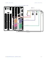
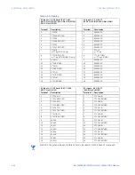
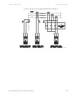
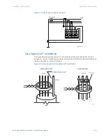
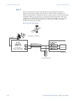
Figure 2-30: RMIO wiring diagram
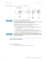
NOTE
NOTE:
D8, D9, and D10 refer to terminals shown on the 8 Series Terminal Identification diagrams.
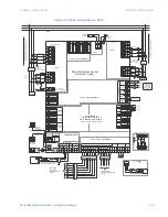
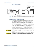
Phase Sequence and Transformer Polarity
For correct operation of the relay features, follow the instrument transformer polarities,
shown in the
Typical Wiring Diagram
above. Note the solid square markings that are
shown with all instrument transformer connections. When the connections adhere to the
drawing, the arrow shows the direction of power flow for positive watts and the positive
direction of vars. The phase sequence is user-programmable for either ABC or ACB
rotation.
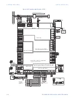
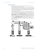
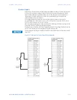
Depending on order code, the 850 relay can have up to four (4) current inputs in each J slot
and K slot. Three of them are used for connecting to the phase CT phases A, B, and C. The
fourth input is a ground input that can be connected to either a ground CT placed on the
neutral from a Wye connected transformer winding, or to a “donut” type CT measuring the
zero sequence current from a grounded system. The relay CTs are placed in a packet
mounted to the chassis of the 850 relay. There are no internal ground connections on the
current inputs. Current transformers with 1 to 12000 A primaries may be used.
CAUTION:
Verify that the relay’s nominal input current of 1 A or 5 A matches the secondary rating
of the connected CTs. Unmatched CTs may result in equipment damage or inadequate
protection.
CAUTION:
IMPORTANT: The phase and ground current inputs correctly measure up to 46 times the
current input’s nominal rating. Time overcurrent curves become horizontal lines for
currents above 20 × PKP.
SCADA, PLC, OR
PERSONAL COMPUTER
OPTOCOUPLER
DATA
RMIO
SHIELD
894218A1.CDR
(*) TERMINATING IMPEDANCE AT EACH END
(typically 120 ohms and 1 nF)
TWISTED PAIR
RMIO +
RMIO -
COMMON
GROUND THE SHIELD AT THE
SCADA/PLC/COMPUTER ONLY
DATA
OPTOCOUPLER
B1
B2
B3
Z (*)
T
8 Series IED
D9: RMIO+
D8: COM
D10:RMIO-
–
+
To switchgear
ground bus
Control power
L
N
Summary of Contents for Multilin 850
Page 10: ...VIII 850 FEEDER PROTECTION SYSTEM INSTRUCTION MANUAL ...
Page 135: ...CHAPTER 3 INTERFACES SOFTWARE INTERFACE 850 FEEDER PROTECTION SYSTEM INSTRUCTION MANUAL 3 41 ...
Page 151: ...CHAPTER 3 INTERFACES SOFTWARE INTERFACE 850 FEEDER PROTECTION SYSTEM INSTRUCTION MANUAL 3 57 ...
Page 153: ...CHAPTER 3 INTERFACES SOFTWARE INTERFACE 850 FEEDER PROTECTION SYSTEM INSTRUCTION MANUAL 3 59 ...
Page 439: ...CHAPTER 7 MONITORING FUNCTIONS 850 FEEDER PROTECTION SYSTEM INSTRUCTION MANUAL 7 19 ...
Page 644: ...11 20 850 FEEDER PROTECTION SYSTEM INSTRUCTION MANUAL FLEXELEMENTS CHAPTER 11 METERING ...