


9–30
850 FEEDER PROTECTION SYSTEM – INSTRUCTION MANUAL
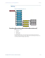
TESTING
CHAPTER 9: FLEXLOGIC AND OTHER SETPOINTS
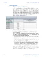
Test LEDs
The Test LEDs setting is used to program the state and color of each LED when in test
mode and Force LEDs is “Enabled”.
NOTE
NOTE:
Test LEDs setpoints here (in test mode) will revert to default values at power-up.
Path:
Setpoints > Testing > Test LEDs
LED 1 (24)
Range for 1(14): Off, Red, Green, Orange
Range for 15(24): Off, Orange
Default: Off
Selects the color of each LED when the relay is in test mode (Simulation State is not set
to “Disabled”) and Force LEDs is “Enabled”. The setpoints Simulation State and Force LEDs
are found under
Setpoints > Testing > Simulation > Setup
.
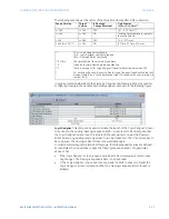
Contact Inputs
The Contact Inputs section is used to program the state of each contact input when in test
mode. The number of Contact Inputs available is dependent on the installed Order Code
options.
NOTE
NOTE:
Contact Inputs setpoints here (in test) will revert to default values at power-up.
Path:
Setpoints > Testing > Contact Inputs
CI 1(X):
Range: Off, On
Default: Off
The item name displays the user configurable name for the contact input.
Output Relays
The Output Relays section is used to program the state of each output relay when the
device is in test mode and Force Relays is “Enabled”.
Select “Off” to force the output relay to the de-energized state, or select “On” to force the
output relay to the energized state.
The number of Output Relays available is dependent on the installed Order Code options.
NOTE
NOTE:
Output Relays setpoints here (in test mode) will revert to default values at power-up.
Path:
Setpoints > Testing > Output Relays
OUTPUT RELAY X
Range: Off, On
Default: Off
Summary of Contents for Multilin 850
Page 10: ...VIII 850 FEEDER PROTECTION SYSTEM INSTRUCTION MANUAL ...
Page 135: ...CHAPTER 3 INTERFACES SOFTWARE INTERFACE 850 FEEDER PROTECTION SYSTEM INSTRUCTION MANUAL 3 41 ...
Page 151: ...CHAPTER 3 INTERFACES SOFTWARE INTERFACE 850 FEEDER PROTECTION SYSTEM INSTRUCTION MANUAL 3 57 ...
Page 153: ...CHAPTER 3 INTERFACES SOFTWARE INTERFACE 850 FEEDER PROTECTION SYSTEM INSTRUCTION MANUAL 3 59 ...
Page 439: ...CHAPTER 7 MONITORING FUNCTIONS 850 FEEDER PROTECTION SYSTEM INSTRUCTION MANUAL 7 19 ...
Page 644: ...11 20 850 FEEDER PROTECTION SYSTEM INSTRUCTION MANUAL FLEXELEMENTS CHAPTER 11 METERING ...