


9–16
850 FEEDER PROTECTION SYSTEM – INSTRUCTION MANUAL
FLEXLOGIC
CHAPTER 9: FLEXLOGIC AND OTHER SETPOINTS
FlexLogic Equation
Path
:
Setpoints > FlexLogic > FlexLogic Equation
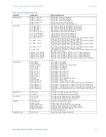
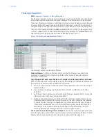
The FlexLogic Equation screen (see following figure from EnerVista 8 Series Setup software)
is one of two options available to configure FlexLogic. The other option is Logic Designer.
Three new time stamp variables: Logic Design Last Saved, Logic Design Last Compiled and
FlexLogic Editor Last Saved, have been included in this screen. Look at the time stamps to
easily see which of the options: FlexLogic Editor or Logic Designer is currently being used.
There are 1024 FlexLogic entries available, numbered from 1 to 1024 (i.e. FlexLogic Entry X
– where X ranges from 1 to 1024) with default END entry settings. If a “Disabled” Element is
selected as a FlexLogic entry, the associated state flag is never set to 1.
Figure 9-5: FlexLogic Equation Editor Screen
The FlexLogic entries are defined as follows.
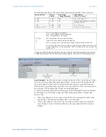
Graphical Viewer
: Clicking on the View button enables the FlexLogic equation to be
presented in graphical format (Read-only). Refer to the “Viewing FlexLogic Graphics”
section for more details.
Logic Design Last Saved, Logic Design Last Compiled, and FlexLogic Editor Last Saved
:
Each of these three read-only variables holds the time stamp that represents the time that
the operation (of the respective variable) was performed.
1.
When no Logic (New file creation) is present these timestamps are set to default text
representations.
2.
Time stamps are displayed in the format ‘Mon DD YYYY HH:MM:SS’ [Jun 22 1981
14:20:00]
3.
Each time a ‘Save’ operation is performed in the ‘FlexLogic Equation Editor’ screen, the
‘FlexLogic Editor Last Saved’ entry gets updated.
4.
Based on the values present at each launch of the ‘FlexLogic Equation Editor’ screen,
internal validation prompts the relevant messages. These prompts must be followed
to ensure that the ‘FlexLogic’ configuration is synchronized with the ‘Logic Designer’.
These three variables are shown in color in the FlexLogic Equation Editor based on
timestamps. Color is used to indicate the change (non-synchronization if any) of
FlexLogic between the FlexLogic Editor and Logic Designer Screens.
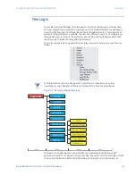
File Conversion and Handling of Time Stamps:
When File Conversion is applied the three
time stamps are processed (either carry forwarded, defaulted, updated with latest PC time)
based on the Source and Destination File versions and Order code supported.
Summary of Contents for Multilin 850
Page 10: ...VIII 850 FEEDER PROTECTION SYSTEM INSTRUCTION MANUAL ...
Page 135: ...CHAPTER 3 INTERFACES SOFTWARE INTERFACE 850 FEEDER PROTECTION SYSTEM INSTRUCTION MANUAL 3 41 ...
Page 151: ...CHAPTER 3 INTERFACES SOFTWARE INTERFACE 850 FEEDER PROTECTION SYSTEM INSTRUCTION MANUAL 3 57 ...
Page 153: ...CHAPTER 3 INTERFACES SOFTWARE INTERFACE 850 FEEDER PROTECTION SYSTEM INSTRUCTION MANUAL 3 59 ...
Page 439: ...CHAPTER 7 MONITORING FUNCTIONS 850 FEEDER PROTECTION SYSTEM INSTRUCTION MANUAL 7 19 ...
Page 644: ...11 20 850 FEEDER PROTECTION SYSTEM INSTRUCTION MANUAL FLEXELEMENTS CHAPTER 11 METERING ...