


1–44
850 FEEDER PROTECTION SYSTEM – INSTRUCTION MANUAL
MUST-READ INFORMATION
CHAPTER 1: INTRODUCTION
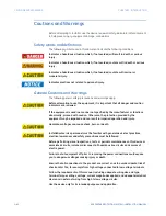
CAUTION:
LED transmitters are classified as IEC 60825-1 Accessible Emission Limit (AEL) Class
1M. Class 1M devices are considered safe to the unaided eye. Do not view directly with
optical instruments.
FASTPATH:
To ensure the settings file inside the relay is updated, wait 30 seconds after a setpoint
change before cycling power.
FASTPATH:
This product is rated to Class A emissions levels and is to be used in Utility, Substation
Industrial environments. Not to be used near electronic devices rated for Class B levels.
Must-read Information
The following general statements apply and are repeated in the relevant sections of the
manual.
FASTPATH:
•
WiFi and USB do not currently support CyberSentry security. For this reason WiFi is
disabled by default if the CyberSentry option is purchased. WiFi can be enabled, but
be aware that doing so violates the security and compliance model that CyberSentry
is supposed to provide.
•
Before upgrading firmware, it is very important to save the current 850 settings to a
file on your PC. After the firmware has been upgraded, it is necessary to load this file
back into the 850.
•
The SNTP, IRIG-B and PTP settings take effect after rebooting the relay.
•
Commands may be issued freely through other protocols than Modbus (i.e., DNP, IEC
104, and, IEC 61850) without user authentication or encryption of data taking place,
even if the relay has the advanced security feature enabled.
•
Note that the factory role password may not be changed.
•
In 850 both DNP and IEC104 protocol can work at the same time, but consider that
there is only one point map. So, both protocols use the same configured points.
•
The 52b contact is closed when the breaker is open and open when the breaker is
closed.
•
The Phase Directional element responds to the forward load current. In the case of a
following reverse fault, the element needs some time – in the order of 8 ms – to
change the directional signal. Some protection elements such as Instantaneous
Overcurrent may respond to reverse faults before the directional signal has changed.
A coordination time of at least 10 ms must therefore be added to all the instantaneous
protection elements under the supervision of the Phase Directional element. If current
reversal is a concern, a longer delay – in the order of 20 ms – is needed.
•
The same curves used for the time overcurrent elements are used for Neutral
Displacement. When using the curve to determine the operating time of the Neutral
Displacement element, substitute the ratio of neutral voltage to Pickup level for the
current ratio shown on the horizontal axis of the curve plot.
•
If the 3-phase VT uses a delta connection and FREQUENCY INPUT is set to J2-3VT, the
positive sequence voltage is used as the supervision voltage. In such conditions, the
true supervision level is internally changed to 1/sqrt(3) of the user setting since the
base of VT here is the phase-phase voltage.
•
To monitor the trip coil circuit integrity, use the relay terminals “FA_1 NO” and “FA_1
COM” to connect the Trip coil, and provide a jumper between terminals “FA_1 COM”
and “FA_1 OPT/V” voltage monitor).
Summary of Contents for Multilin 850
Page 10: ...VIII 850 FEEDER PROTECTION SYSTEM INSTRUCTION MANUAL ...
Page 135: ...CHAPTER 3 INTERFACES SOFTWARE INTERFACE 850 FEEDER PROTECTION SYSTEM INSTRUCTION MANUAL 3 41 ...
Page 151: ...CHAPTER 3 INTERFACES SOFTWARE INTERFACE 850 FEEDER PROTECTION SYSTEM INSTRUCTION MANUAL 3 57 ...
Page 153: ...CHAPTER 3 INTERFACES SOFTWARE INTERFACE 850 FEEDER PROTECTION SYSTEM INSTRUCTION MANUAL 3 59 ...
Page 439: ...CHAPTER 7 MONITORING FUNCTIONS 850 FEEDER PROTECTION SYSTEM INSTRUCTION MANUAL 7 19 ...
Page 644: ...11 20 850 FEEDER PROTECTION SYSTEM INSTRUCTION MANUAL FLEXELEMENTS CHAPTER 11 METERING ...