


6–132
850 FEEDER PROTECTION SYSTEM – INSTRUCTION MANUAL
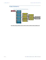
POWER ELEMENTS
CHAPTER 6: PROTECTION SETPOINTS
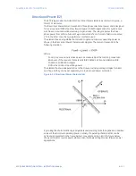
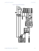
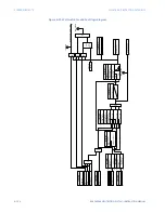
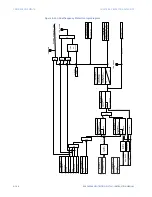
Wattmetric Ground Fault (32N)
The Wattmetric Ground Fault element, also called Wattmetric Zero-sequence Directional
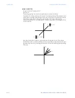
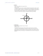
element, responds to power derived from zero-sequence voltage and current in a direction
specified by the element characteristic angle. The angle can be set within all four
quadrants and the power can be active or reactive. Therefore, the element may be used to
sense either forward or reverse ground faults in inductive, capacitive or resistive networks.
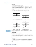
The inverse time characteristic allows time coordination of elements across the network.
Typical applications include Ground Fault protection in grounded/ungrounded/resistor-
grounded/resonant-grounded distribution networks, or directionalizing other non-
directional ground elements.
Path
:
Setpoints > Protection > Group 1(6) > Power > Wattmetric Ground Fault 1(X)
FUNCTION
Range: Disabled, Trip, Alarm, Latched Alarm, Configurable
Default: Disabled
VT INPUT
Range: dependant upon the order code
Default: Ph VT Bnk1-J2
This setting provides the selection for the voltage bank input. If ‘Calculated VN’ is
selected, the voltage input shall be either ‘Ph VT Bnk1-J2’ or ‘Ph VT Bnk1-K2’. If ‘Measured
Vx’ is selected, the voltage input shall be either ‘Ax VT Bnk1-J2’ or ‘Ax VT Bnk2-K2’.
VOLTAGE
Range: Calculated VN, Measured Vx
Default: Calculated VN
The element uses neutral voltage (that is, three times the zero-sequence voltage). The
setting allows selecting the internally calculated neutral voltage, or externally supplied
voltage (broken delta VT connected to the auxiliary channel bank of the relay). When the
latter selection is made, the auxiliary channel must be identified by the user as a neutral
voltage under the VT bank settings. This element operates only if the auxiliary voltage is
configured as neutral.
OPERATING VOLTAGE PICKUP
Range: 0.02 to 3.00 x VT in steps of 0.01 x VT
Default: 0.20 x VT
The setting specifies the minimum zero sequence voltage supervising the directional
power measurement. This threshold is higher than possible unbalance during normal
operation of the system. Typically, this setting is selected at 0.1 to 0.2 x VT for the
ungrounded or resonant grounded systems, and at 0.05 to 0.1 x VT for solidly or resistor-
grounded systems. When using externally supplied voltage via the auxiliary voltage
channel, 1 x VT is the nominal voltage of this channel as per VT bank settings. When
using internally calculated neutral voltage, 1 x VT is the nominal phase-to-ground
voltage per the VT bank settings.
CT INPUT
Range: dependant upon the order code
Default: CT Bank 1 -J1
This setting provides selection for the current bank input.
Summary of Contents for Multilin 850
Page 10: ...VIII 850 FEEDER PROTECTION SYSTEM INSTRUCTION MANUAL ...
Page 135: ...CHAPTER 3 INTERFACES SOFTWARE INTERFACE 850 FEEDER PROTECTION SYSTEM INSTRUCTION MANUAL 3 41 ...
Page 151: ...CHAPTER 3 INTERFACES SOFTWARE INTERFACE 850 FEEDER PROTECTION SYSTEM INSTRUCTION MANUAL 3 57 ...
Page 153: ...CHAPTER 3 INTERFACES SOFTWARE INTERFACE 850 FEEDER PROTECTION SYSTEM INSTRUCTION MANUAL 3 59 ...
Page 439: ...CHAPTER 7 MONITORING FUNCTIONS 850 FEEDER PROTECTION SYSTEM INSTRUCTION MANUAL 7 19 ...
Page 644: ...11 20 850 FEEDER PROTECTION SYSTEM INSTRUCTION MANUAL FLEXELEMENTS CHAPTER 11 METERING ...